
User manual


28
EN
Instruction Manual
EL 9000 HP Series
Date: 10-31-2011
About the device
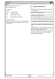
2.2 Devicespecicdata
Mainsinput
Mains voltage
Mains frequency
Mains fuse
DCinput
Input voltage U
nom
80V 160V 400V 460V 750V
Input power P
nom
- permanent power
Input current I
nom
400A 200A 100A 100A 50A
Overvoltage protection threshold
max. allowed input voltage
100V 180V 460V 483V 850V
Voltagecontrol
Adjustment range
0…80V 0…160V 0…400V 0…460V 0…750V
Display resolution
100mV 100mV 100mV 100mV 100mV
Accuracy**
<0.2% of U
nom
Currentcontrol
Adjustment range
0…400A 0…200A 0…100A 0…100A 0…50A
Display resolution
100mA 100mA 10mA 10mA 10mA
Accuracy**
Powercontrol
Adjustment range
0…4800W 0…4800W 0…4800W 0…4800W 0…4800W
Display resolution
1W 1W 1W 1W 1W
Accuracy**
Resistancecontrol
Adjustment range 1
0…2.5Ω 0…5Ω 0…5Ω 0…5Ω 0…20Ω
Display resolution
1mΩ 10mΩ 10mΩ 10mΩ 10mΩ
Adjustment range 2
0…50Ω 0…100Ω 0…200Ω 0…200Ω 0…400Ω
Display resolution
100mΩ 100mΩ 100mΩ 100mΩ 100mΩ
Accuracy**
Dynamicvalues
Current rise and fall time***
Level
Times (pulsed operation)
Rise/fall time
Accuracy**
Trigger input*
Batterytestfeature
Modes
Battery protection
Display
Display
Analogueinterface*
Set value inputs
Monitor outputs
Control signals
Error signals
Outputs
Cooling
Type
Ambient temperature
Terminals
Load input
System Bus
Analogue interface
DimensionsWxHxD
Weight
Supportedinterfacecards
Articlenumber 33 200 231 33 200 234 33 200 237 33 901 237 33 200 253
* for technical specification see section "Analogue interface"
*** Rise and fall time are defined at 10%...90% and 90%...10% of the nominal value
All single values, which specify a tolerance are typical values
** Accuracy is defined as the max. allowed difference between actual value and set value, always related to the nominal value.
Example: nom. value is 400A and accuracy is given with 0.2%. A set value of 20A may thus result in an actual value of 19.2A...20.8A.
19" x 4U x 460mm
26kg
CAN, USB, RS232, GPIB, Ethernet
rear side, 7 pole screw clamp
rear side, 15 pole Sub-D socket
reference voltage
temperature controlled fans
0…70°C with derating 20W/°C
rear side, M8 screw terminal
0...10V for U / I / P / R (0...100% set value)
0...10V for U / I (0...100% actual value)
internal/external, input on/off, R range 1 or 2
overvoltage / overtemperature
final discharging voltage adjustable
time and consumed battery capacity
2 x 40 characters, illuminated
<10%
yes, for external level switching
current / resistance / power
<50us
2 adjustable levels per control mode
2 adjustable, 50us..100s
adjustable, 30us…200ms
EL9750-50
115V/230V selectable
50/60Hz
EL9400-100S01EL9160-200 EL9400-100EL9080-400
T2,5A
4800W, with temperature related derating
3000W at 20°C ambient temp.
<2% of the selected resistance range, 0,3% of the maximum input current
<0.2% of I
nom
<0.1% of U
nom
1.1 * U
nom
<2% of P
nom