Pub. 988-0152-011 www.eaglesonar.
Copyright © 2003 Eagle Electronics All rights reserved. Eagle® is a registered trademark of Eagle Electronics Marine-Tex is a trademark of Illinois Tool Works Inc. Eagle Electronics may find it necessary to change or end our policies, regulations, and special offers at any time. We reserve the right to do so without notice. All features and specifications subject to change without notice. All screens in this manual are simulated. For free owner's manuals and other information, visit our web site: www.
Table of Contents Sec. 1: Read Me First! .............................................................. 1 Capabilities and Specifications: Cuda 240.................................... 2 How your Sonar Works................................................................. 4 How your GPS Works ................................................................... 4 Introduction to GPS and WAAS................................................... 5 How to Use this Manual: Typographical Conventions................
FasTrack .................................................................................. 49 Fish I.D. (Fish Symbols & Depths) ......................................... 50 FishTrack ................................................................................. 51 Grayline ..................................................................................... 51 Overlay Data ............................................................................... 52 Ping Speed & HyperScroll....................
Find a Waypoint.......................................................................... 86 Navigate to a Waypoint .............................................................. 88 Set Man Overboard (MOB) Waypoint........................................ 89 Navigate Back to MOB Waypoint .......................................... 89 Trails ........................................................................................... 90 Creating and Saving a Trail ................................................
Overlay Data ............................................................................. 113 To Select Data for Display: ............................................... 114 To Turn Off Displayed Data: ............................................ 114 To Change Displayed Data Font Size: ............................. 115 Pop-Up Help .............................................................................. 116 Position Pinning........................................................................
Section 1: Read Me First! How this manual can get you out on the water, fast! Welcome to the exciting world of digital sonar and GPS! We know you're anxious to begin finding fish, but we have a favor to ask. Before you grab the unit and begin installing it, please give us a moment or two to explain how our manual can help you get the best performance from your combination fish finder and GPS receiver. First, we want to thank you for buying a Eagle sonar/GPS unit.
If you're having difficulty with your sonar, you can find an answer to the most common problems in Section 5, Sonar Troubleshooting. The manual switches from sonar to navigation in Section 6, which introduces you to Basic GPS Operations. This section features a onepage GPS Quick Reference on page 79. Section 6 contains short, easy-to-scan GPS lessons that follow one another in chronological order. They're all you'll need to know to find your way on the water quickly.
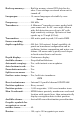
Back-up memory: .......... Built-in memory stores GPS data for decades. User settings are stored when unit is turned off. Languages:...................... 10; menu languages selectable by user. Sonar Frequency:...................... 200 kHz. Transducer:...................... A Skimmer transducer comes packed with your sonar unit. Its 20° cone angle offers a wide fish detection area of up to 60º with high sensitivity settings. Operates at boat speeds up to 70 mph (61 kts). Transmitter: ...................
Plot Trails: ...................... 10 savable; up to 9,999 points per trail. Zoom range:.................... 39 ranges; 0.02 to 4,000 miles. NOTICE! The storage and operation temperature range for your unit is from -4 degrees to +167 degrees Fahrenheit (-20 degrees to +75 degrees Celsius). Extended storage or operation in temperatures higher or lower than specified will damage the liquid crystal display in your unit. This type of damage is not covered by the warranty.
& Accessories on page 9. If you're new to GPS, read on, and you can later impress your friends with your new-found knowledge.) First, think of your unit as a small but powerful computer. (But don't worry — we made this unit easy to use, so you don't need to be a computer expert to find your way!) The unit includes a keypad and a screen with menus so you can tell it what to do. The screen also lets the unit show your location on a GPS plotter, as well as point the way to your destination.
GPS proved so useful for civilian navigation that the federal government discontinued SA on May 2, 2000, after the military developed other methods to deny GPS service to enemy forces. Reliable accuracy for civilian users jumped from 100 meters (330 feet) under SA to the present level of 10 to 20 meters (about 30 to 60 feet.) Twenty-four satellites orbit 10,900 nautical miles above the Earth, passing overhead twice daily.
GPS alone is plenty accurate for route navigation, but the U.S. Federal Aviation Administration has special aircraft navigation needs that go beyond basic GPS. So, the FAA has developed a program to boost GPS performance with its Wide Area Augmentation System, or WAAS. The FAA commissioned the system on July 11, 2003. WAAS is designed to increase GPS accuracy to within 7.
tal line depth cursor on the sonar screen. The arrow keys help you move around the menus so you can execute different commands. They are represented by symbols like these, which denote the down arrow key, the up arrow, the left arrow and the right arrow: ↓ ↑ ← →. Keyboard The other keys perform a variety of functions. When the text refers to a key to press, the key is shown in bold, sans serif type. For example, the "Enter/Icons" key is shown as ENT and the "Menu" key is shown as MENU.
Section 2: Installation & Accessories Preparations You can install the sonar and GPS systems in some other order if you prefer, but we recommend this installation sequence: CAUTION: You should read over this entire installation section before drilling any holes in your vehicle or vessel! 1. Determine the approximate location for the sonar/GPS unit, so you can plan how and where to route the power/transducer cable. This will help you make sure you have enough cable length for the desired configuration. 2.
Remember, the transducer location and installation is the most critical part of a sonar installation. Recommended Tools and supplies If you prefer the option of routing the cable through the transom, you will need a 5/8" drill bit. NOTE: The following installation types also call for these recommended tools and required supplies that you must provide (supplies listed here are not included): Transom installation Tools include: two adjustable wrenches, drill, #29 (0.136") drill bit, flathead screwdriver.
boat hulls have a flat keel pad that offers a good mounting surface. On vee hulls, try to place the transducer where the deadrise is 10° or less. Deadrise less than 10° Strakes Pad Left, vee pad hull; right, vee hull. A pod style transducer is shown here, but the principle is the same for Skimmers inside a hull. 4. If the transducer is mounted on the transom, make sure it doesn't interfere with the trailer or hauling of the boat.
Transom Transducer centerline Hull bottom Align transducer centerline with hull bottom. However, there are times when you may need to adjust the transducer slightly higher or lower. (The slots in the mounting brackets allow you to loosen the screws and slide the transducer up or down.) If you frequently lose bottom signal lock while running at high speed, the transducer may be coming out of the water as you cross waves or wakes. Move the transducer a little lower to help prevent this.
Second, the transducer angle cannot be adjusted for the best fish arches on your sonar display. (This is not an issue for flasher-style sonars.) Lack of angle adjustment can be particularly troublesome on hulls that sit with the bow high when at rest or at slow trolling speeds. Third, a transducer CAN NOT shoot through wood and metal hulls. Those hulls require either a transom mount or a thru-hull installation.
Reassemble the transducer and bracket and place them against the transom. Again, check to see if you can move the transducer so it's parallel with the ground. If you can, then go to step 3. If it doesn't, repeat step 2, but use a different alignment letter until you can place the transducer on the transom correctly. Ratchets Insert bolt and check transducer position on transom. 3. Assembling the transducer.
Transom Transom Position transducer mount on transom and mark mounting holes. Side view shown at left and seen from above at right. 5. Attaching transducer to transom. Remove the transducer from the bracket and re-assemble it with the cable passing through the bracket over the bolt as shown in the following figures. Route cable over bolt and through bracket. Side view shown at left and seen from above at right. Attach the transducer to the transom.
6. Route the transducer cable through or over the transom to the sonar unit. Make sure to leave some slack in the cable at the transducer. If possible, route the transducer cable away from other wiring on the boat. Electrical noise from the engine's wiring, bilge pumps, VHF radio wires and cables, and aerators can be picked up by the sonar. Use caution when routing the transducer cable around these wires. WARNING: Clamp the transducer cable to the transom close to the transducer.
3. Route the transducer cable alongside the trolling motor shaft. Use plastic ties (not included) to attach the transducer cable to the trolling motor shaft. Make sure there is enough slack in the cable for the motor to turn freely. Route the cable to the sonar unit and the transducer is ready for use. Transducer mounted on trolling motor, side view.
If the arch slopes up – but not back down – then the front of the transducer is too high and needs to be lowered. If only the back half of the arch is printed, then the nose of the transducer is angled too far down and needs to be raised. NOTE: Periodically wash the transducer's face with soap and water to remove any oil film. Oil and dirt on the face will reduce the sensitivity or may even prevent operation.
Testing Determines Best Location Ideally, the shoot-thru transducer should be installed as close to the transom as possible, close to the centerline. This will give you the best performance during high speed maneuvers. Transducer location (trolling speed) Transducer location (high speed) Shoot-thru-hull transducer locations for high speed or trolling speed operation.
2. Next, take the transducer out of the water and place it in the water in the sump of the boat, face down. (The transducer face is shown in the figure on the following page.) Notice how the signal strength decreases. The second bottom signal will probably disappear and the bottom signal intensity will likely decrease. 3. Now move the transducer around to find the best location with the strongest possible bottom signal.
Spread epoxy here Sand this surface Epoxy transducer to hull. WARNING: Use only the epoxy available from LEI. It has been formulated to work with these installation procedures. Other epoxy types may be too thin or may not cure to the right consistency for optimum transducer performance. 2. The epoxy consists of the epoxy itself and a hardener. Remove the two compounds from the package and place them on the paper plate.
5. After the epoxy has cured, route the cable to the sonar unit and it's ready to use. POWER AND CABLE CONNECTIONS The unit works from a 12-volt battery system. For the best results, attach the power cable directly to the battery. You can attach the power cable to an accessory or power buss, however you may have problems with electrical interference. Therefore, it's safer to go ahead and attach the power cable directly to the battery.
lead, black is negative or ground. Make sure to attach the in-line fuse holder to the red lead as close to the power source as possible. For example, if you have to extend the power cable to the battery or power buss, attach one end of the fuse holder directly to the battery or power buss. This will protect both the unit and the power cable in the event of a short. It uses a 3-amp fuse.
Top ALWAYS VERIFY DIMENSIONS. Cut along this line In-dash mounting template for Cuda 240. NOTE: This figure is not printed to scale. Bracket Installation Mount the unit in any convenient location, provided there is clearance when it’s tilted for the best viewing angle. You should also make sure there is enough room behind the unit to attach the power/transducer cable. (See the following drawings, which show the dimensions of a mounted Cuda 240 sonar unit.
107.5 [4.23] 82.7 [3.26] 156 [6.26] 12.09 [0.48] 76.9 [3.03] 70.3 Millimeter [2.77] [Inch] Front view (left) and side view (right) showing dimensions of the Cuda 240 when mounted on quick release bracket. If you wish, you can fill in the hole around the cable with a good marine sealant compound. (Some marine dealers stock cable hole covers to conceal the opening.) This unit uses a quick release mounting bracket.
Ratchet Rear (away from viewer) Screw hole Power/transducer cable Cable slot Cuda 240 quick release mounting bracket. Slots in the base allow routing the cable from beneath the mount. Attach the unit to the bracket by first connecting the power/transducer cable. Then, hold the sonar unit vertically and slide it onto the bracket from above. (The back of the unit should be touching the front of the bracket as you lower it into position.
Depress ratchets to release. Swivel base Adjust viewing angle: use one hand to press and release the springloaded ratchets while you move the unit with the other hand. An optional GBSA-3 swivel base is shown with the quick release bracket. Portable Sonar Installation Like many Eagle products, the Cuda 240 sonar is capable of portable operation. It uses the optional PPP-12 portable power pack. The power pack and portable transducers expand the uses for your sonar.
NOTE: When the unit is not in use, we recommend you unplug the power connector to reduce the possibility of corrosion or battery drain. When you store the unit, always remove the batteries because dead batteries can leak and corrode the contacts. After installing the batteries, plug the cable's power connector into the socket on the battery compartment cover. Route the cable's unit connector and about 6 inches of cable through the opening under the sonar mount.
If the batteries do lose a charge, you can sometimes restore them by placing them in a warm room or car interior. A better way is to replace them with batteries that have been kept warm. WARNING: Never heat the batteries over an open flame or direct hot air onto them. A fire or explosion could result. Portable Transducer Assembly Recommended tools for installation include a slotted screw driver and two adjustable wrenches. Assemble the transducer and bracket as shown in the following figure.
Suction cup Bracket Hull Transducer Portable transducer installed on boat transom. NOTE: For optimum operation, the portable transducer should be adjusted so that it is parallel to the ground. For more information on this, see the earlier segment on Transducer Orientation and Fish Arches. Now that you have your unit installed, move on to Sec. 3, Basic Sonar Operations. There, we'll present a series of step-by-step tutorials to teach you the basics of your sonar operation.
Section 3: Basic Sonar Operation KEYBOARD BASICS The unit sounds a tone when you press any key. This tells you the unit has accepted a command. Numbers in the photo correspond to key explanations below: 2 3 7 6 4 8 9 1 5 Eagle Cuda 240 Sonar, front view, showing screen and keyboard. (A close-up of the keyboard can be found at the beginning of Sec. 6) 1. PWR/LIGHT (Power & Light) – The PWR key turns the unit on and off and activates the backlight. 2.
4. ARROW KEYS – These keys are used to navigate through the menus, make menu selections, move the plotter cursor and sonar chart cursor and enter data. 5. ENT (Enter) – This key allows you to save data, accept values or execute menu commands. It is also used to create event marker icons. 6. EXIT – The Exit key lets you return to the previous screen, clear data or erase a menu. 7. WPT – (Waypoint) The Waypoint key is used to save and recall waypoints, search for waypoints and access the waypoint list.
Main Menu. Main Menu Commands There are four "basic" Main Menu commands that you'll really want to read more about. They are: • Screen commands (CONTRAST, BRIGHTNESS and DISPLAY MODE): change the appearance of the display screen. Use these commands to adjust how the screen looks under various lighting conditions. • Sounds command: controls sound levels for keystrokes and alarms. If you don't like to hear a beep each time you press a key, you can turn all sounds off by setting the volume to zero.
Sonar Menu The Sonar Menu contains commands for the major sonar features and options. You access the Sonar Menu by pressing the MENU key one time. You run a command by using ↑ or ↓ to highlight the command and then pressing ENT. To clear the menu screen and return to the Page display, press EXIT. Sonar Page Menu. Most of these functions are discussed in Sec. 4, Advanced Sonar Operation. Sonar Menu Commands The Sonar Menu contains commands for the major sonar features and options.
• Overlay Data command: chooses what types of information (such as water temperature) to show overlaid on the sonar chart screen. • Sonar Features command: launches the Sonar Features menu which controls many functions and options, including screen color mode, auto depth and sensitivity, surface clarity, noise rejection, Fish I.D. symbols, the zoom bar and zone bar. • Ping Speed command: sets the rate at which sonar pings are made. Pages The Cuda 240 has three major Sonar display options.
Sonar chart display options (from left) full sonar chart and split zoom. Sonar chart digital data display option. You can customize how the Sonar Page pictures and other data are displayed in many ways. We'll discuss all of those features and options in the Advanced Sonar Operation section, but to show you how easy the sonar unit is to operate, the following page contains a simplified, 10step quick reference that will cover most fish finding situations.
Basic Sonar Quick Reference 1. Mount the transducer and unit. Connect the unit to electric power and the transducer. 2. Launch your boat. 3. To turn on the unit, press and release PWR key. 4. Head for your fishing grounds. Your unit automatically displays digital depth and surface water temperature in the corner of the screen. The auto settings will track the bottom, displaying it in the lower portion of the screen.
Sonar Operations As you can see from the quick reference on the previous page, basic operation is pretty easy, right out of the box. If you are a sonar novice, try operating the unit with the factory defaults until you get a feel for how it's working. As you're learning the basics, there is one setting you might want to tinker with from time to time — Sensitivity. Sensitivity controls the unit's ability to pick up echoes. If you want to see more detail, try increasing the sensitivity, a little at a time.
You can change the sensitivity level whether you are in Auto Sensitivity mode or Manual Sensitivity mode. The adjustment method works the same in both modes, but it gives you slightly different results. Adjusting sensitivity in Auto Sensitivity Mode is similar to manually adjusting a car's speed with the accelerator pedal while cruise control is on. You can tell the car to run faster, but when you let off the gas the cruise control automatically keeps you from running slower than the minimum speed setting.
NOTE: If you want to change the sensitivity in Manual Mode, first turn off Auto Sensitivity: from the Sonar Page, press MENU|↓ to AUTO SENSITIVITY|ENT|↑ to SENSITIVITY|ENT. Press ↓ or ↑ to pick a different sensitivity setting. When it's set at the desired level, press EXIT. Important Tip: While you are experimenting and learning, it's possible to scramble the settings so that the sonar picture disappears from your screen.
Other Free Training Aids The following section discusses Fish I.D., fish alarms and other features in greater detail. If you or a friend has Internet access, you can also learn more about interpreting what you see on your sonar screen. Visit our web site, WWW.EAGLESONAR.COM. Be sure to check out the free Sonar Tutorial, which includes animated illustrations and more pictures of actual sonar returns, all described in detail.
Notes 42
Section 4: Sonar Options & Other Features Material in this section is arranged in alphabetical order. ASP (Advanced Signal Processing) The ASP feature is a noise rejection system built into the sonar unit that constantly evaluates the effects of boat speed, water conditions and interference. This automatic feature gives you the best display possible under most conditions. The ASP feature is an effective tool in combating noise. In sonar terms, noise is any undesired signal.
3. Press ↓ or ↑ to select a setting, then press ENT. 4. To return to the previous page, press EXIT|EXIT. Alarms This unit has three different types of sonar alarms. The first is a Fish Alarm. It sounds when the Fish I.D. feature determines that an echo is a fish. Another alarm is the Zone Alarm, which consists of a bar on the side of the screen. Any echo on the chart that appears inside this bar triggers the alarm. The last alarm setting is the Depth Alarm, which has both a Shallow and a Deep setting.
3. Press ↑ or ↓ until the depth is correct, then press ENT. 4. Press ← to SHALLOW ALARM ENABLED|ENT|EXIT. 5. To turn off the alarm, press MENU|MENU|↓ to ALARMS|ENT |↓ to SONAR ALARMS|ENT|ENT|EXIT. To switch to a different depth setting, open the Sonar Alarms menu and repeat the instructions in step 3 above. To adjust and turn on the deep alarm: 1. Press MENU|MENU|↓ to ALARMS|ENT |↓ to SONAR ALARMS|ENT. 2. Press ↓ to DEEP ALARM DEPTH|ENT. 3. Press ↑ or ↓ until the depth is correct, then press ENT. 4.
3. To set the upper boundary for the Zone Alarm, use ← or→ to select UPPER, then press ↑ or ↓ to move the top of the bar to the desired depth. 4. To set the lower boundary for the Zone Alarm, use ← or→ to select LOWER, then press ↑ or ↓ to move the bottom of the bar to the desired depth. 5. Press EXIT|← to ZONE ALARM ENABLED|ENT|EXIT|EXIT|EXIT. Now, any echo — fish, bottom, structure — within the zone alarm's depth range will trigger the zone alarm. 6.
Chart Speed The rate that echoes scroll across the screen is called the chart speed. The default is maximum; we recommend that you leave the speed set there for virtually all fishing conditions. However, you might consider experimenting with chart speed when you are stationary or drifting very slowly. You may sometimes achieve better images as you slow down the chart speed to match how fast you are moving across the bottom.
Cursor line Depth box At left, Sonar Page menu with Depth Cursor command selected. At right, sonar chart with the depth cursor active. The line indicates the large fish is 40.53 feet deep. The cursor can be moved to any location on the screen, letting you pinpoint the depth of a target. 1. From the Sonar Page, press MENU|↓ to DEPTH CURSOR|ENT. 2. The depth cursor appears. Press ↓ to lower the cursor line; press ↑ to raise the cursor line. 3. To clear the depth cursor, press EXIT.
2. The Depth Range Control Scale appears. Press ↑ or ↓ to select a different depth range. A dark bar highlights the selected range. Range numbers in gray cannot be selected. 3. When the new range is selected, press EXIT to clear the menu. Depth Range - Manual You have complete control over the range when the unit is in the manual mode. There are 12 depth ranges, from 5 feet to 800 feet. To switch to Manual Depth Range: 1. First, turn off automatic depth range.
When the boat is not moving, fish signals are long, drawn out lines on a normal chart display. FasTrack converts the graph to a vertical bar graph that, with practice, makes a useful addition to fishing at a stationary location. Fish I.D. (Fish Symbols & Depths) The Fish I.D. feature identifies targets that meet certain conditions as fish. The microcomputer analyzes all echoes and eliminates surface clutter, thermoclines, and other signals that are undesirable.
To turn the Fish I.D. feature on: 1. From the Sonar Page, press MENU|↓ to SONAR FEATURES|ENT. 2. Press ↓ to FISH ID SYMBOLS|ENT|EXIT|EXIT. To turn off Fish I.D., repeat these instructions. FishTrack The FishTrack feature shows the depth of a fish symbol when it appears on the display. This lets you accurately gauge the depth of targets. This feature is available only when the Fish I.D. feature is on. The default setting for FishTrack is off.
If you have two signals of equal size, one with gray and the other without, then the target with gray is the stronger signal. This helps distinguish weeds from trees on the bottom, or fish from structure. Grayline is adjustable. Experiment with your unit to find the Grayline setting that's best for you. At left, Sonar Page menu with Grayline command selected. At right, the Grayline control bar. To adjust the Grayline level: 1. From the Sonar Page, press MENU|↓ to GRAYLINE|ENT. 2.
Overlay Data command on the Sonar Menu, at left. Overlay Data Shown selection menu, right. In this example, we scrolled down the data list to highlight "Ground Speed." When selected, a check mark appears beside the data type. (If you wish, you may now use ↓ or ↑ to select other Data Types for display.) Data list showing "Ground Speed" turned on to display on Sonar Page. 3. To return to the previous page, press EXIT|EXIT. To turn off displayed data: 1. Press MENU|↓ to OVERLAY DATA|ENT. 2.
The selected data type will be displayed in the new size. (To change the font size for another Data Type, press ENT and repeat these steps, beginning with step two above.) 3. To return to the previous page, press EXIT. Sonar chart with Overlay Data turned on. This example shows Depth, Water Temperature and the Ground Speed of the boat. Ping Speed & HyperScroll Ping Speed controls the rate at which the transmitter and transducer broadcast sonar sound waves — pings — into the water.
At left, Sonar Menu with Ping Speed command selected. Ping Speed Control Bar, right, at default setting. To change Ping Speed: 1. From the Sonar Page, press MENU|↓ to PING SPEED|ENT. 2. The Ping Speed Control Bar appears. Press ↑ to increase ping speed; press ↓ to decrease ping speed. When it's set at the desired level, press EXIT. To adjust Sensitivity: 1. From the Sonar Page, press MENU|ENT. 2. The Sensitivity Control Bar appears. Press ↓ to decrease sensitivity; press ↑ to increase sensitivity.
1. Press MENU|MENU|↓ to SYSTEM SETUP|ENT|↓ to RESET OPTIONS|ENT. 2. Press ↑ or ↓ to YES|ENT. 3. All the menus are cleared and all options are returned to the factory settings. System Menu with Reset Options command selected. Sensitivity & Auto Sensitivity The sensitivity controls the ability of the unit to pick up echoes. Sensitivity can be adjusted, because water conditions vary greatly.
The control bar used to adjust sensitivity up or down is the same whether the unit is in the automatic or manual mode. In automatic you can adjust sensitivity up to 100 percent but the unit will limit your minimum setting. In auto, the unit will continue to make small adjustments, allowing for the setting you selected. In manual mode, you have complete control over sensitivity, with the ability to set it anywhere from zero to 100 percent.
Tip: For quicker sensitivity adjustments, try leaving the Sensitivity Control Bar on the screen as the chart scrolls. You can see the changes on the screen as you press the up or down arrows. This is handy when there's a lot of clutter in the water, and you are matching the sensitivity to rapidly changing water conditions. Set Keel Offset This unit measures water depth from the face of the transducer.
2. The Keel Offset dialog box appears with a plus (+) sign at the front of the box. 3. Press ↑ until the displayed number is + 1.5, then press EXIT. The depth indicators now accurately show the water depth from surface to bottom. Sonar Color Mode The default color scheme for the sonar chart is grayscale, but we offer other variations to suit your viewing preferences. You can select the chart to be displayed in reverse grayscale, bottom black or FishReveal mode.
Full Sonar Chart. The Overlay Data (depth and water temperature) are each set to a different text size. Split Zoom Sonar Chart A split chart shows the underwater world from the surface to the bottom on the right side of the screen. The left side shows an enlarged version of the right side. The zoom range shows at the bottom left corner of the screen. Split Zoom Sonar Chart. Image at left shows the left window zoomed to 2X. The right image shows the left window zoomed to 4X.
Digital Data/Chart Sonar Simulator This unit has a built-in simulator that lets you run it as if you were on the water. All sonar features and functions are useable. When in simulator mode, you will see [Simulator Mode] in the Sonar Page title bar. To use the simulator: 1. From the Sonar Page, press MENU|MENU|↓ to SONAR SIMULATOR|ENT. 2. Turn off Sonar Simulator by pressing MENU|MENU|↓ to SONAR SIMULATOR|ENT|EXIT. NOTE: If you turn on your unit before attaching a transducer, it may enter a demo mode.
Sonar Menu with Stop Chart command selected. The box is unchecked, indicating that the chart is scrolling across the screen. Surface Clarity The markings extending downward from the zero line on the chart are called "surface clutter." These markings are caused by wave action, boat wakes, temperature inversion and more. The surface clarity control reduces or eliminates surface clutter signals from the display.
Zoom & Zoom Bar "Zooming" the display is used to enlarge small detail, fish signals and the bottom with its associated structure. The 2X zoom doubles the size of all echoes on the screen. The 4X zoom quadruples the size of the echoes. You can also turn on a zoom bar on the far right side of the screen; this shows which echoes will be displayed on the screen when the Zoom commands are used. For example, turning on the 2X zoom will show all echoes that are between the top and bottom of the 2X zoom bar.
Notes 64
Section 5: Sonar Troubleshooting If your unit is not working, or if you need technical help, please use the following troubleshooting section before contacting the factory customer service department. It may save you the trouble of returning your unit for repair. For contact information, refer to the last page, just inside the back cover of this manual. Unit won't turn on: 1. Check the power cable's connection at the unit. Also check the wiring. 2. Make certain the power cable is wired properly.
This causes the sonar to automatically increase its Discrimination or noise rejection feature. This can cause the unit to eliminate weaker signals such as fish or even structure from the display. 3. The water may be deeper than the sonar's ability to find the bottom. If the sonar can't find the bottom signal while it's in the automatic mode, the digital sonar display will flash continuously. It may change the range to limits far greater than the water you are in.
NOISE A major cause of sonar problems is electrical noise. This usually appears on the sonar's display as random patterns of dots or lines. In severe cases, it can completely cover the screen with black dots, or cause the unit to operate erratically, or not at all. To eliminate or minimize the effects of electrical noise, first try to determine the cause. With the boat at rest in the water, the first thing you should do is turn all electrical equipment on the boat off. Make sure the engine is also off.
Notes 68
Section 6: Basic GPS Operations This section addresses the unit's GPS operations. Before you turn on the unit and find where you are, it's a good idea to learn about the different keys, the four GPS Page screens and how they all work together. BUT, if you just can't wait to get outside, turn to the one-page Quick Reference on page 79. Keyboard 2 3 7 6 4 8 9 5 1 Eagle Cuda 240, close-up of unit's keyboard. 1.
5. ENT/ICONS (Enter & Icons) – This key allows you to save data, accept values or execute menu commands. It is also used to create event marker icons. 6. EXIT – The Exit key lets you return to the previous screen, clear data or erase a menu. 7. WPT – (Waypoint) The Waypoint key is used to save and recall waypoints, search for waypoints and access the waypoint list. It's also involved in some navigation functions. 8. ZOUT – (Zoom Out) – This key lets you zoom the screen out.
Main Menu. The Main Menu commands and their functions are: Screen command: changes the contrast or brightness of the display screen. Sounds command: enables or disables the sounds for key strokes and alarms and sets the alarm style. Alarms command: turns GPS or sonar alarms on or off and changes alarm thresholds. Route Planning command: used to plan, view or navigate a route. My Trails command: shows, hides, creates and deletes plot trails. Also used to navigate or backtrack a trail.
Pages The unit has four GPS Page displays that represent the four major operating modes. They are the Satellite Status Page, the Navigation Page, Plotter Page and the Position Page. They are accessed by pressing PAGES|← to GPS, then using ↑ or ↓ to select a Page. (Clear the Pages Menu by pressing EXIT.) Pages Menu, showing the GPS display options. Sonar Pages Like the GPS Page options, there are four Sonar Page displays.
Satellite Page. Left view indicates unit has not locked on to any satellites and does not have a fix on its position. Center view shows satellites being scanned. Right view shows satellite lock-on with a 3D position acquired (latitude, longitude and altitude.) This screen shows a graphical view of the satellites that are in view. Each satellite is shown on the circular chart relative to your position. The point in the center of the chart is directly overhead.
Navigation Page This screen has a compass rose that not only shows your direction of travel, but also the direction to a recalled waypoint. To get to the Navigation Page: Press PAGES|← to GPS|↑ or ↓ to NAVIGATION|EXIT. The navigation screen looks like the one below when you're not navigating to a waypoint or following a route or trail. Your position is shown by an arrow in the center of the screen. Your trail history, or path you've just taken, is depicted by the line extending from the arrow.
Speed (ground speed) is the velocity you are making over the ground. (If you wish, you can customize the Speed window to display Closing Speed instead. Closing Speed is also known as velocity made good. It's the speed that you're making toward the waypoint. For instructions, see the Customize Page Displays entry in Sec. 7.) Track is the heading, or the current direction you are actually traveling. Bearing is the direction of a line-of-sight from your present position to the destination.
Current track or heading, shown in degrees Waypoint symbol Compass bearing to destination Cross track error range (off course indicator) Bearing arrow Trail line Course line Left cross track error line Cross track error range (off course indicator) Navigation information displays Navigation Page, backtracking a trail while creating a new trail. In the example figure above, the driver is headed north (a 12º track) toward a waypoint 12º (bearing) away.
The Position Page can be fully customized. The lower window can display ten of 22 types of navigation information. For customization instructions see the Customize Page Displays topic in Sec. 7, System and GPS Setup Options. Some of the popular information displays include: Altitude is height above sea level, not ground level. Speed (ground speed) is the velocity you are making over the ground. Closing Speed is also known as velocity made good. It's the speed that you're making toward a destination.
The arrow in the center of the screen is your present position. It points in the direction you're traveling. The flashing line extending from the back of the arrow is your plot trail, or path you've taken. The plotter's zoom range is the distance across the screen. This number shows in the lower right corner of the screen. In the first example figure below, the range is 4,000 miles from the left edge of the display to the right edge.
GPS Quick Reference Start outdoors, with a clear view of the open sky. As you practice, try navigating to a location at least a few blocks away. While you're learning, navigation in too small an area will constantly trigger arrival alarms. 1. Install the unit. (See complete installation details beginning on page 9.) 2. To turn on the Cuda 240, press and release PWR key. 3. Opening screen displays the GPS plotter at the 4,000 mile zoom range.
Viewing the Plotter: Zoom & Cursor Arrow Keys The plotter is presented from a bird's eye view perspective. The current zoom range shows in the lower right corner of the screen. 1. Press the ZIN key (zoom in) to move in closer and see greater detail in a smaller geographic area. 2. Press the ZOUT key (zoom out) to move farther away and see less detail, but a larger geographic area. When you are traveling, the plotter will automatically move as you move.
Navigate to cursor. In this example, the cursor has selected waypoint 004. 3. Press MENU|ENT and the Cuda 240 will begin navigating to the cursor location. The Plotter Page will display a dotted line from your current position to the cursor position. The Navigation Page displays a compass rose showing navigation information to your destination. See the following examples. The Plotter Page at left clearly shows the course line connecting your current position to your destination.
The Cuda 240 stops showing navigation information. Find Your Current Position Finding your current position is as simple as turning Cuda 240 on. Under clear sky conditions, the unit automatically searches for satellites and calculates its position in approximately one minute or less. NOTE: "Clear sky" means open sky, unobstructed by terrain, dense foliage or structures. Clouds do not restrict GPS signal reception.
Find Distance From Point to Point You can also measure distance between two other points on the plotter. 1. While on the Plotter Page press: MENU|↓ to FIND DISTANCE|ENT. 2. Center your cursor over the first position. (A rubber band line appears, connecting your current position to the cursor's location.) Press ENT to set the first point, and the rubber band line disappears. 3. Move the cursor to the second position. The rubber band line reappears, connecting the first point you set to the cursor.
Sequence for setting a waypoint. Step 1: while traveling, quickly press WPT twice to call up Find Waypoint screen (shown at left) and set a point. Step 2: a message says the waypoint has been saved (shown center). Step 3: vehicle continues on its way; number waypoint symbol is visible on plotter (shown at right). NOTE: The Quick Save method uses the default waypoint symbol until you edit an existing waypoint and change its symbol.
previous page display. The waypoint is saved and automatically given a name with a sequential number, such as "waypoint 001." The waypoint symbol and number appear on the plotter and in the waypoint list. Create Waypoint by Average Position This feature sets a waypoint at the current position after taking several position readings and averaging them. This boosts waypoint position accuracy by helping to eliminate errors caused by atmospheric conditions and other factors. 1. Press WPT|↓ to CREATE NEW|ENT. 2.
To delete a waypoint from the plotter: 1. Use the arrow keys to select the waypoint with the cursor. 2. Press WPT|→ to DELETE|ENT|← to YES|ENT. To return to the previous page and clear the cursor, press EXIT. To delete all waypoints at one time: press MENU|MENU|↓ to SYSTEM SETUP|ENT|↓ to DELETE ALL MY WAYPOINTS|ENT|← to YES|ENT. To return to the previous page, press EXIT|EXIT. Edit a Waypoint Waypoint Name To edit waypoint name: 1. Press WPT|ENT|↓ to waypoint name|ENT|→ to EDIT NAME|ENT. 2.
You will use the Find Waypoint commands to choose a waypoint you want to navigate to, or to choose one for editing. 1. Press WPT. To look up the nearest waypoint, just press ENT, then scroll down the list to find the desired waypoint; or, to look by name, press ↓ to FIND BY NAME|ENT. For this example, use FIND BY NAME. 2. If your waypoint list is a long one, you can spell out the waypoint name in the FIND BY NAME box to search for it.
Plotter screen showing Find Waypoint. 7. To clear the search and return to the last page displayed, press EXIT|EXIT. (Before you completely exited out of the Search menus, you could have gone looking for another place.) Navigate To a Waypoint You can select any waypoint visible on the Plotter Page with the cursor, then use the Navigate to Cursor command (we described how to do that earlier in this section).
Course line (dotted) Trail line (flashing) Off course range, set at 0.20 mile Navigation Page, navigating toward a waypoint and leaving a trail. Set Man Overboard (MOB) Waypoint One of boating's most terrifying events is having a friend or family member fall overboard. This situation can be deadly on any body of water — fresh or salt. It's particularly dangerous at night or if you're out of sight of land.
Navigating to Man Overboard: Navigation Page, left and center, and Plotter Page, right. The victim is astern of the vessel; the GPS shows which direction to steer to for the rescue. The man overboard position is also stored in the waypoint list for future reference. It can be edited the same as any other waypoint. To cancel navigation to MOB, press MENU|MENU|↓ to CANCEL NAVIGATION|ENT|← to YES|ENT. The unit stops showing navigation information.
To Save a Trail 1. Press MENU|MENU|↓ to MY TRAILS|ENT. Visible symbol Active symbol Sequence for saving a trail and beginning a new one. At left, My Trails command. Center, the Trails Menu. The arrow to the right of Trail 3 indicates the trail is "active," and the check to the left indicates the trail is visible on the plotter display. The right figure shows the Edit Trail menu, with the Active command selected. 2. Press ↓ to the Active Trail Name|ENT. 3. Press ↓ to ACTIVE|ENT.
You can save and recall up to 10 different plot trails. Tip: Another quick way to stop recording one trail and begin a new one is to use the New Trail command: Press MENU|MENU|↓ to MY TRAILS|ENT|ENT. Caution: You also have the option of completely turning off trail recording, under the trail Options command. However, if the Update Active Trail option is left turned off, it will cancel the automatic trail creation feature.
Edit a Trail Name To edit a trail name: press MENU|MENU|↓ to MY TRAILS|ENT|↓ to trail name|ENT|ENT. Press ↑ or ↓ to change the first character, then press → to the next character and repeat until the name is correct. Press ENT then EXIT|EXIT|EXIT|EXIT to return to the previous page display. Tip: You can quickly call up the Edit Trail menu by selecting a trail on the plotter with the cursor. Simply move the cursor over a trail and a pop-up box appears. Press WPT and the Edit Trail menu opens.
tween them is "navigating a trail" follows a trail forward (from start to end) while "backtracking" follows a trail in reverse (from end to start.) When hiking at walking speed with a hand-held GPS, we often just use visual back trailing because it is a bit better at following each little turn on a foot path. At faster speeds, such as the highway or on the water, the Navigate Trail and Backtrack Trail commands are handy. Visual Trailing 1.
Figure 1. Figure 2. Figure 4. Figure 3. Navigate a trail menu sequence: Fig. 1, My Trails command. Fig. 2, Trails Menu. Fig. 3, Edit Trail Menu. Fig. 4, Edit Route Menu with Navigate command highlighted for Trail 1. A trail is always converted to a "route" when you navigate the trail. On the Plotter Page, the trail you are navigating is represented by a flashing line. The Navigation Page will also show the navigated trail as a flashing line.
Trail point Present position arrow Navigate trail, plotter views: at left boater is heading straight toward trail point 3. Center, when the point is reached, Arrival Alarm goes off and the steering arrow points toward next trail point. At right, boater has reached point 3 and has turned northeast to follow trail to point 4. (Flashing trail line is turned off for clarity.
3. Press → to DELETE TRAIL|↓ to NAVIGATE|ENT. 4. Press ↓ to NAVIGATE|→ to REVERSE|ENT|← to NAVIGATE|ENT. The unit begins showing navigation information along the trail, in reverse. NOTE: If you are already located at or near the end of your trail, the arrival alarm will go off as soon as you hit Enter. Just press EXIT to clear the alarm and proceed. 5. Now, begin moving and follow your Cuda 240. 6.
Cursor selects icon location, left; Select Icon Symbol menu, center; Boat Ramp icon on plotter, right. (Cursor has been moved for clarity.) Create Icon at Current Position 1. While you are traveling, press ENT and the screen shows a "Select Icon Symbol" menu. 2. Press ← or ↑ or → or ↓ to select your icon symbol, then press ENT. The icon appears on the plotter.
The Delete All Icons command will ask if you are sure. Press ← to YES|ENT. All icons will be deleted from the plotter. The Delete by Symbol command will launch the Select Symbol menu. Press ← or ↑ or → or ↓ to select the icon symbol to delete, then press ENT. A message appears saying all icons with the selected symbol have been deleted. The Delete From Plotter command will prompt you to move the cursor over an icon to select it. After selecting the icon, press ENT and it disappears from the plotter.
Route Planning command on Main Menu, left, will open the Route List screen, right. 2. Press ↓|↓|↑ or ↓ to route name|ENT|↓ to (ROUTE END)|ENT|↓ to ADD FROM PLOTTER|ENT. The Plotter Page appears with the cursor showing. Edit Route menu, left. Edit Route Waypoints menu, right, with Add From Plotter command selected. 3. Use the Zoom keys and arrow keys to move the plotter and cursor until the cursor is centered on the waypoint or event marker icon where you want your route to begin.
Route creation sequence: At left, the Plotter Page shows the waypoints we want to visit in our route. Set the first route point at waypoint (001). Center, move cursor to the next waypoint in the route and press Enter. Waypoint added message appears. Right, continue adding waypoints until you reach the end of the route. 5. Move the cursor to the next point in the route (waypoint 2 in our example; this could also be a spot where you need to turn or change direction), and press ENT to set the next waypoint.
Edit a Route You can edit the route name if you wish. 1. From the NAVIGATION PAGE, press MENU|ENT or from the PLOTTER PAGE press MENU|MENU|↓ to ROUTE PLANNING|ENT. 2. Press ↓ to route name|ENT|ENT. 3. Press ↑ or ↓ to change the first character, then press → to move the cursor to the next character and repeat until the name is correct, then press ENT. Return to the previous page by pressing EXIT|EXIT|EXIT|EXIT. You can edit the route by adding and removing waypoints. 1.
Route Planning command on Main Menu, left; Routes menu, center; Edit Route menu, right. Navigate command is selected. 2. Press ↓ to select route name|ENT|↓ to NAVIGATE|ENT|ENT. 3. Upon arrival at your destination, cancel navigation: press MENU|MENU|↓ to CANCEL NAVIGATION|ENT|← to YES|ENT. The following figures show what the Navigation Page and Plotter Page look like while navigating a route. Navigate a Route in Reverse Here's how you run a route backward, from the end waypoint to the beginning waypoint: 1.
Figure 4. Figure 5. Figure 6. Navigating along a route: Figs. 1 & 4 show the Plotter Page (top) and Navigation Page (bottom) while running a route. Boater is heading straight for waypoint 3. In Figs. 2 & 5, the traveler has arrived at Wpt 3; the arrival alarm has been triggered and the bearing arrow on the compass rose has turned to point toward Wpt 4, off to the northeast. In Figs. 3 & 6 the traveler has turned northeast on his new course and is heading straight for Wpt 4, which is 0.43 miles away.
Section 7: System & GPS Setup Options Alarms This unit has several GPS alarms. The factory default setting has all the alarms turned on. You can turn the alarms off and on and change their distance settings. You can set an arrival alarm to flash a warning message and sound a tone when you cross a preset distance from a waypoint. For example, if you have the arrival alarm set to 0.1 mile, then the alarm will flash a message when you come within 0.1 mile of the recalled waypoint.
3. To change distance settings, scroll ↓ or ↑ to select the desired category, then press →|ENT to activate the distance dialog box. Press ↑ or ↓ to change the first character, then press → to the next character and repeat until the name is correct. 4. When your adjustments are finished, return to the last page displayed by repeatedly pressing EXIT. IMPORTANT ALARM NOTES: Anchor Alarm - The anchor alarm may be triggered even when you're sitting still. This typically happens when using small (less than 0.
GPS Auto Search on the Satellite Status Menu. You can force the unit to immediately kick into auto search mode. Here's how: 1. Press PAGES and switch to the Satellite Status screen. 2. Press MENU|↓ to GPS AUTO SEARCH|ENT|← to YES|ENT. Coordinate System Selection The Coordinate System Menu lets you select the coordinate system to use when displaying and entering position coordinates. Menus for changing coordinate system used to display positions. To get to Coordinate System Selection: 1.
and tenths of a second (36° 28' 40.9"). It can also show position in: UTM (Universal Transverse Mercator) projection; MGRS (Standard); MGRS (Standard + 10); Map Fix; Loran TD; British, Irish, Finnish, German, New Zealand, Swedish, Swiss, Taiwan, Greek and Military grids. UTM's are marked on USGS topographic charts. This system divides the Earth into 60 zones, each 6 degrees wide in longitude.
Map Fix Map Fix is used with charts or maps. This system asks for a reference position in latitude/longitude, which you take from a marked location on the map. It then shows the present position as distance on the map from that reference point. For example, if it shows a distance of UP 4.00" and LEFT 0.50", you then measure up four inches and to the left a half-inch from the reference point on the map to find your location. To configure a map fix: To use this format, you need to follow these steps in order.
Press ↓ to SELECT ORIGIN WAYPOINT|ENT|ENT|ENT to bring up the waypoint list. Select the waypoint that you saved the reference point under and press ENT. The unit displays a waypoint information screen with the command SET AS ORIGIN selected; press ENT and the unit returns to the Configure Map Fix menu. Finally, press EXIT to erase this menu. Now press ↑ to COORD SYSTEM|ENT, select MAP FIX from the list and press ENT|EXIT. All position information now shows as a distance from the reference point you chose.
GPS Setup Menu, left; GPS Simulator menu, right. Make the desired settings, then turn the simulator on by highlighting the GPS SIMULATOR ON box and pressing ENT. Press EXIT|EXIT|EXIT to erase this menu. A message and tone appear periodically, warning you that the simulator is on. To turn the simulator off, repeat the above steps or turn the unit off. While in simulator mode, you can press EXIT to clear the steering and speed boxes from the screen while continuing the simulation.
Tip: You can pick any spot on the plotter to begin your simulation session by using the Initialize GPS command. This makes your unit think it's located at the position you select. See it's entry following the entry for Hide GPS Features. Hide GPS Features If there is no GPS antenna/receiver module attached to this unit, the GPS menus and features can be hidden from view with this command. The default setting is off, allowing you to rotate between the Sonar Page and the GPS pages and features.
the present position to the destination waypoint. As you travel toward the destination, the unit automatically begins zooming in — one zoom range at a time — always keeping the destination on the screen. To turn this feature on, from the Plotter Page, press MENU|↓ to AUTO ZOOM|ENT|EXIT. Repeat these steps to turn it off. Plotter Orientation By default, this receiver shows the plotter with north always at the top of the screen. This is the way most maps and charts are printed on paper.
First, press PAGES, use the arrow keys to select the right page, then press EXIT. To select data for display: 1. From the Plotter or Sonar page, press MENU|↓ to OVERLAY DATA|ENT. 2. Press ↓ or ↑ to select Data Type|ENT. Overlay Data command on the Sonar Menu, at left. Overlay Data Shown selection menu, right. In this example, we scrolled down the data list to highlight "Ground Speed." When selected, the data type shifts to the top of the data list and a check mark appears beside the data type.
2. Press ↓ or ↑ to select Data Type|ENT. The selected data type disappears from the top of the list and reverts to its previous, unchecked position. (If you wish, you may now use ↓ or ↑ to select other Data Types to turn off.) 3. To return to the previous page, press EXIT|EXIT. To change displayed data font size: 1. From the Plotter or Sonar page, press MENU|↓ to OVERLAY DATA|ENT. 2. Press ↓ or ↑ to select Data Type|press → or ← to Data Size|EXIT. The selected data type will be displayed in the new size.
Pop-up Help Help is available for virtually all of the menu labels on this unit. By highlighting a menu item and leaving it highlighted for a few seconds, a "pop-up" message appears that describes the function of the menu item. This feature is on by default. To set up Popup Help: Press MENU|MENU|↓ to SYSTEM SETUP|ENT|↓ to POPUP HELP. With the option highlighted, press ENT to check it (turn on) and uncheck it (turn off). After the option is set, press EXIT to return to the page display.
1. Press MENU|MENU|↓ to GPS SETUP|ENT|↓ to POSITION PINNING|ENT. 2. Press EXIT|EXIT to return to the previous page. Reset Options This command is used to reset all features, options and settings to their original factory defaults. This is useful when you have changed several settings and want to return the unit to basic automatic operation. 1. Press MENU|MENU|↓ to SYSTEM SETUP|ENT|↓ to RESET OPTIONS|ENT. 2. Press ↑ or ↓ to YES|ENT. 3. All menus are cleared and all options are returned to factory settings.
To adjust the display's brightness: Press ↓ to BRIGHTNESS. Press → or ← to move the bar. The left end of the scale is minimum brightness; the right end is maximum brightness. To adjust the screen's display mode: Press ↓ to DISPLAY MODE|ENT|press ↑ or ↓ to select mode|EXIT. Display Mode menu. Set Language This unit's menus are available in 10 languages: English, French, German, Spanish, Italian, Danish, Swedish, Russian, Dutch and Finnish. To select a different language: 1.
To set the Month: Press ↓ to MONTH|ENT. Press ↑ or↓ to select the month, then press ENT. To set the Day: Press ↓ to DAY|ENT. Press ↑ or↓ to select the day, then press ENT. To set the Year: Press ↓ to YEAR|ENT. Press ↑ or↓ to select the year, then press ENT. The last field in this menu is CONFIG DST. This feature allows your unit to automatically adjust with the time change caused by Daylight Saving Time (you should only have to set it once).
At left, Main Menu with Software Information command selected. At right, the Software Information screen. 1. Press MENU|MENU|↓ to SYSTEM SETUP|ENT|↓ to SOFTWARE INFO|ENT. 2. Read the information displayed on the screen. 3. To return to the last page displayed, press EXIT|EXIT. Sounds and Alarm Sound Styles Sounds triggered by key strokes and alarms can be adjusted: You first press MENU|MENU|↓ to SOUNDS|ENT. Sounds command, left. At right, the Sounds menu.
To set Alarm Sounds: Press ↓ to ALARM SOUNDS. With the option highlighted, press ENT to check it (turn on) and uncheck it (turn off). After the option is set, press EXIT|EXIT to return to the page display. To set Alarm Volume: Press ↓ to VOLUME. Press → or ← to move the bar. The left end of the scale is low volume; the right end is high volume. After the option is set, press EXIT|EXIT to return to the page display. To set Alarm Style: Press ↓ to ALARM STYLE|ENT.
Main Menu, left, Trails Menu, center, Trail Options, right. Delete All Trails To remove all of the trails from memory: from the Trails Menu, press → to DELETE ALL|ENT|← to YES|ENT. Update Trail Option This menu lets you change the way the trail updates occur. WARNING: If you uncheck the Update Trail option, automatic trail creation and recording will be turned off. You must turn it back on to record trails. The default setting is on. From the Trails Menu, press → to OPTIONS|ENT.
With one of the Update Criteria selected, use the cursor arrows to highlight either the UPDATE RATE or UPDATE DISTANCE data entry boxes and press ENT. Press ↑ or ↓ to change the first character, then press → to the next character and repeat until the entry is correct. Press EXIT to return to the Trail Options Menu. Trail Options menu: Update Time Rate setting, left, and Update Distance setting, right.
Trail Visible/Invisible and Other Trail Options The name, maximum number of points in the trail, activity, and visibility are all changed on the Edit Trail menu screen. The Active setting determines whether or not the unit is recording new points for a particular trail. On the Edit Trail menu, press ↓ or ↑ to highlight the section you wish to change, then press ENT. Make your changes, then press EXIT to erase this menu.
Section 8: Supplemental Material FCC Compliance This device complies with Part 15 of the U.S. Federal Communications Commission (FCC) Rules. Operation is subject to the following two conditions: (1) this device may not cause harmful interference, and (2) this device must accept any interference received, including interference that may cause undesired operation. Changes or modifications not expressly approved by the manufacturer could void the user's authority to operate the equipment.
Notes 126
Index A Accessories, 1, 5, 23, 24 Sec.
111, 115 Create and Save, 99 Delete, 101 Navigate, 102, 103 Update Criteria, 122 Update Rate, 122 Trip Calculator, 71, 104 Trip Down Timer, 104 Trip Up Timer, 104 U Units of Measure, 33, 124 Utilities, 71, 104 W WAAS, 3, 5, 7, 119 Waypoints, 2, 3, 5, 7, 32, 70, 71, 74, 75, 76, 77, 78, 79, 82, 83, 84, 85, 86, 87, 88, 89, 90, 95, 96, 97, 99, 100, 101, 102, 103, 104, 105, 106, 108, 109, 110, 111, 112, 113, 115, 118, 122 Delete, 85 Edit, 86 Save, 83 Z Zooming, 3, 4, 32, 35, 37, 59, 60, 63, 66, 70, 75, 78, 79,
EAGLE DATABASES LICENSE AGREEMENT THIS IS A LEGAL AGREEMENT BETWEEN THE END-USER WHO FIRST PURCHASES THIS PRODUCT AS A CONSUMER ITEM FOR PERSONAL, FAMILY, OR HOUSEHOLD USE ("YOU") AND EAGLE ELECTRONICS, A DIVISION OF LEI, THE MANUFACTURER OF THIS PRODUCT ("WE", "OUR", OR "US"). USING THE PRODUCT ACCOMPANIED BY THIS LICENSE AGREEMENT CONSTITUTES ACCEPTANCE OF THESE TERMS AND CONDITIONS. IF YOU DO NOT ACCEPT ALL TERMS AND CONDITIONS, PROMPTLY RETURN THE PRODUCT WITHIN 30 DAYS OF PURCHASE.
DATABASES LIMITED WARRANTY "We", "our", or "us" refers to Eagle Electronics, a division of LEI, the manufacturer of this product. "You" or "your" refers to the first person who purchases the product as a consumer item for personal, family, or household use. The Databases Limited Warranty applies to the one or more databases that your product may contain. We refer to each of these as a "Database" or together as the "Databases.
EAGLE ELECTRONICS FULL ONE-YEAR WARRANTY "We," "our," or "us" refers to EAGLE ELECTRONICS, a division of LEI, the manufacturer of this product. "You" or "your" refers to the first person who purchases this product as a consumer item for personal, family, or household use. We warrant this product against defects or malfunctions in materials and workmanship, and against failure to conform to this product's written specifications, all for one (1) year from the date of original purchase by you.
How to Obtain Service… …in the USA: We back your investment in quality products with quick, expert service and genuine Eagle replacement parts. If you're in the United States and you have technical, return or repair questions, please contact the Factory Customer Service Department. Before any product can be returned, you must call customer service to determine if a return is necessary. Many times, customer service can resolve your problem over the phone without sending your product to the factory.
Accessory Ordering Information for all countries To order Eagle accessories such as power cables or transducers, please contact: 1) Your local marine dealer or consumer electronics store. Most quality dealers that handle marine electronic equipment or other consumer electronics should be able to assist you with these items. To locate an Eagle dealer near you, visit our web site, www.eaglesonar.com and look for the Dealer Locator. Or, you can consult your telephone directory for listings. 2) U.S.
Visit our web site: www.eaglesonar.com Eagle Pub.