Pub. 988-0158-031 www.eaglesonar.
Copyright © 2007 Navico All rights reserved. Eagle® is a registered trademark of Navico No part of this manual may be copied, reproduced, republished, transmitted or distributed for any purpose, without prior written consent of Eagle Electronics. Any unauthorized commercial distribution of this manual is strictly prohibited. Eagle Electronics may find it necessary to change or end our policies, regulations, and special offers at any time. We reserve the right to do so without notice.
Table of Contents Introduction..............................................................................................................................................4 Installation...............................................................................................................................................5 Display....................................................................................................................................................
Introduction : Congratulations on your purchase of an Eagle EVR-100 marine band VHF radio. Designed for international operation, allows you to transmit and receive on all international channels in the VHF marine band, as assigned by the International Union (ITU). The EVR-100 is approved with commercial-grade standards to give you clear, reliable communication. NOTE: According to WEEE regulations, the user should not dispose the product when damaged, but rather send it back to Eagle for disposal.
Installation: This Eagle radio allows you to make a maritime distress call to facilitate search and rescue. To be effective as a safety device, this radio must be used only within the geographic range of a shore-based VHF marine Channel 16 distress and safety watch system. The geographic range may vary but under normal conditions is approximately 20 nautical miles. Installation Options There are two ways to install the radio. You can choose: • a deck or overhead mounted gimbal installation.
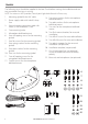
Checklist The following items should be supplied in the box. Check before starting the installation and contact your dealer if an item is missing. NOTE: An antenna is NOT provided. Consult your Eagle dealer for advice if necessary. 1. 2. Mounting gimbal for the VHF radio Power supply cable with inbuilt 3 Amp fuse 3. External speaker connection cable with white (+) wire and black (-) wire 4. Two mounting knobs 5. Microphone bulkhead mount 6. Four self-tapping screws for the mounting gimbal 7.
Gimbal Installation 1. Hold the mounting gimbal at the chosen location and use a soft pencil to mark the screw hole positions onto the mounting surface. 2. If you can’t reach behind the mounting surface to attach the nuts, use the self-tapping screws instead of the flat screws shown in the picture. If you’re drilling into fiberglass, use a drill bit smaller than 3/16” (5mm) to drill the pilot holes. Otherwise, drill the four screw holes where marked, using a 3/16” (5mm) drill bit.
5. Use the two short M5x10 screws to screw the mounting brackets to the sides of the radio. 6. Screw each M5x32 screw through the screw hole in the mounting bracket, then attach the stopper. If your bulkhead exceeds 0.51” (13mm), the stopper can be discarded if necessary. 7. Tighten the M5x32 screws until the radio is held firmly against the rear of the bulkhead.
Connect the Radio Cables The connectors are on the rear of the base unit, as follows: 1. External Speaker connector. Plug the external speaker cable jack into the connector BEFORE powering on the radio. Use a 4 Ohm 4 Watt external speaker. 2. RED Power wire. Connect this to the POSITIVE (+) battery terminal. Check that a 3 Amp fuse is installed on this power cable close to the battery. 3. BLACK Power wire. Connect this to the NEGATIVE (-) battery terminal. 4. ANT. A radio antenna is not supplied.
The Completed Installation External speaker VHF Antenna External speaker connection cable Antenna connection cable Fuse on RED power cable BLACK power cable Battery Base unit with microphone* * Actual model may differ from that shown 10 EAGLE EVR-100 Operation Instructions
Display LCD symbols and Meanings Symbol Meaning Transmitting. TX HI LO Transmission power. High (HI) 7W or Low (LO) 1W. BUSY Receiver busy with an incoming signal. WX Weather channel. WX ALT Weather Alert. Alarm beeps will sound. PRI Priority channel is selected. SCAN Scanning channels. DW Dual Watch mode. ALL ALL channels scan mode. C1 C2 C3 Shows which of the 3 favourite channels, if any, are selected, otherwise blank. (small) (large) Channel selected.
Basic Operation and Key Functions Key VOL/PWR SQL 16/9 WX UIC 3CH +/- 12 Function Volume and Power. Turn clockwise to power on. Continue to turn until a comfortable volume is reached. VOL/PWR will also adjust the settings of an external speaker, if connected Squelch or Threshold Level. Sets the threshold level for the minimum receiver signal. Turn fully counterclockwise until random noise is heard, then turn slowly clockwise until the random noise disappears.
SCAN + CH - SKIP H/L PTT To scan only one of your favourite channels, press 3CH then immediately press and release SCAN. If you want to scan all three favourite channels, press 3CH then immediately press and hold SCAN. To add a favourite channel for the first time, select that channel then hold 3CH to store it in the CH1 location. Repeat the procedure to store two more favourite channels in the CH2 and CH3 locations respectively.
Radio Operation Turning Your Radio On/Off Rotate VOL/PWR knob to turn the radio on or off. Rotate to adjust the volume to a comfortable level. Adjusting Squelch Squelch is used to eliminate static and background noise and allows for silent operation of your radio until a transmission is received. If the squelch is too high, only the strongest transmissions can be heard, and when too low, intermittent static and noise are heard. To set Squelch: 1. Turn SQL knob fully counter-clockwise.
Scanning Features Your radio is equipped with 2 types of scan options: All Scan, 3CH Scan (Favourite Channel Scan). If there are no channels added as favourite channels, the default is All Scan. This function automatically searches for transmissions on the channel being scanned. If a signal is received, the scan stops on the receiving channel as long as it is present and the SCAN indicator flashes. If the signal is lost for 3 seconds, the radio resumes scanning.
NOAA Weather Channels To receive a NOAA (National Oceanic and Atmospheric Administration) weather channel, press the WX key. The transceiver will go to the last selected weather channel. Press the + CH - keys to scroll through the available WX channels. To exit from the NOAA weather channels, press the WX key to terminate WX mode and return to the previous working channel, or press 16/9 to access the priority channels.
Appendix A - Technical Specifications GENERAL Power Supply: Current drain: Transmit Receive Useable channels: Mode: PHYSICAL LCD display (viewing): Backlight control: Antenna connector: Temperature Range: Waterproof: Dimensions: Weight: Frequency stability: Frequency control: GPS/NMEA input: Comm port: DSC: FEATURES Flush Mount kit: Local/Distant control: Position polling: Group Call: Channel Naming: Dual watch, Favourite channel scan, All scan: TRANSMITTER Frequency: Output power: Transmitter protection: M
Appendix B - Troubleshooting 1. The transceiver will not power up. A fuse may have blown OR there is no voltage getting to the transceiver. a) Check the power cable for cuts, breaks, or squashed sections. b) After checking the wiring, replace the 3 Amp fuse (1 spare fuse is supplied). c) Check the battery voltage. This must be greater than 10.5V. 2. The transceiver blows the fuse when the power is switched on. The power wires may have been reversed.
Appendix C - Frequency Charts International Channel Chart CH TX RX MODE TRAFFIC TYPE (MHz) (MHz) 01 156.050 160.650 D Public Correspondence 02 156.100 160.700 D Public Correspondence 03 156.150 160.750 D Public Correspondence 04 156.200 160.800 D Port Operations 05 156.250 160.850 D Port Operations, Selected VTS Areas 06 156.300 156.300 S Inter-ship Safety 07 156.350 160.950 D Port Operations 08 156.400 156.400 S Commercial (inter-ship only) 09 156.450 156.
66 156.325 160.925 D 67 156.375 156.375 S 68 156.425 156.425 S 69 156.475 156.475 S 70 156.525 156.525 71 156.575 156.575 S 72 156.625 156.625 S 73 156.675 156.675 S 74 156.725 156.725 S 77 156.875 156.875 S 78 156.925 161.525 D 79 156.975 161.575 D 80 157.025 161.625 D 81 157.075 161.675 D 82 157.125 161.725 D 83 157.175 161.775 D 84 157.225 161.825 D 85 157.275 161.875 D 86 157.325 161.925 D 87 157.375 161.975 D 88 157.425 162.
USA Channel Chart CH TX RX MODE TRAFFIC TYPE (MHz) (MHz) 01A 156.050 156.050 S Port Operations, Selected VTS Areas 03A 156.150 156.150 S US Government, Coast Guard 05A 156.250 156.250 S Port Operations, Selected VTS Areas 06 156.300 156.300 S Inter-ship Safety 07A 156.350 156.350 S Commercial 08 156.400 156.400 S Commercial (inter-ship only) 09 156.450 156.450 S Recreational Calling Channel 10 156.500 156.500 S Commercial 11 156.550 156.550 S Commercial, VTS in Selected Areas 12 156.600 156.
68 156.425 156.425 S 69 156.475 156.475 S 70 156.525 156.525 71 156.575 156.575 S 72 156.625 156.625 S 73 156.675 156.675 S 74 156.725 156.725 S 77 156.875 156.875 S 78A 156.925 156.925 S 79A 156.975 156.975 S 80A 157.025 157.025 S 81A 157.075 157.075 S 82A 157.125 157.125 S 83A 157.175 157.175 S 84 157.225 161.825 D 85 157.275 161.875 D 86 157.325 161.925 D 87 157.375 161.975 D 88 157.425 162.025 D 88A 157.425 157.
CANADA Channel Chart CH TX RX (MHz) (MHz) MODE 01 156.050 160.650 02 156.100 160.700 03 156.150 160.750 04A 156.200 156.200 05A 156.250 156.250 06 156.300 156.300 07A 156.350 156.350 08 156.400 156.400 09 156.450 156.450 10 156.500 156.500 11 156.550 156.550 12 156.600 156.600 13 156.650 156.650 14 156.700 156.700 15 156.750 156.750 16 156.800 156.800 17 156.850 156.850 18A 156.900 156.900 19A 156.950 156.950 20 157.000 161.600 21 157.050 161.650 21A 157.050 157.050 21B --161.650 22A 157.
64 64A 65A 66A 67 68 69 70 71 72 73 74 77 78A 79A 80A 81A 82A 83 83A 83B 84 85 86 87 88 156.225 156.225 156.275 156.325 156.375 156.425 156.475 156.525 156.575 156.625 156.675 156.725 156.875 156.925 156.975 157.025 157.075 157.125 157.175 157.175 --157.225 157.275 157.325 157.375 157.425 160.825 156.225 156.275 156.325 156.375 156.425 156.475 156.525 156.575 156.625 156.675 156.725 156.875 156.925 156.975 157.025 157.075 157.125 161.775 157.175 161.775 161.825 161.875 161.925 161.975 162.
WEATHER Channels CH WX01 WX02 WX03 WX04 WX05 WX06 WX07 WX08 WX09 WX10 RX (MHz) 162.550 162.400 162.475 162.425 162.450 162.500 162.525 161.650 161.775 163.
NAVICO FULL TWO-YEAR EAGLE VHF WARRANTY “We,” “our,” or “us” refers to NAVICO, the manufacturer of this EAGLE VHF product. “You” or “your” refers to the first person who purchases this product as a consumer item for personal, family or household use. We warrant this product against defects or malfunctions in materials and workmanship, and against failure to conform to this product’s written specifications, all for two (2) years from the date of original purchase by you.
How to Obtain Service . . . … in the USA: We back your investment in quality products with quick, expert service and genuine Eagle replacement parts. If you’re in the United States and you have technical, return or repair questions, please contact the Factory Customer Service Department. Before any product can be returned, you must call customer service to determine if a return is necessary. Many times, customer service can resolve your problem over the phone without sending your product to the factory.
Accessory Ordering Information for all countries To order Eagle accessories such as power cables or transducers, please contact: 1) Your local marine dealer or consumer electronics store. Most quality dealers that handle marine electronic equipment or other consumer electronics should be able to assist you with these items. To locate an Eagle dealer near you visit our web site or consult your telephone directory for listings. 2) U.S. customers: LEI Extras Inc.
Notes:
Notes:
Notes:
Eagle Pub.