Pub. 988-0143-751 www.eaglesonar.
Copyright © 2004 LEI-Eagle All rights reserved. Eagle® is a registered trademark of LEI FishEasy® 240 is a registered trademark of LEI Eagle Electronics may find it necessary to change or end our policies, regulations, and special offers at any time. We reserve the right to do so without notice. All features and specifications subject to change without notice. All screens in this manual are simulated.
Table of Contents Introduction.......................................................................................1 Capabilities and Specifications: FishEasy 240 Family .....................1 NOTICE! ...........................................................................................3 How Sonar Works.................................................................................3 Transducer Installation ..................................................................5 Preparations .............
Display – Opening Screen..................................................................43 Chart Scroll (stopping and starting) .................................................44 Screen Display Modes or Pages.........................................................45 Full Chart .......................................................................................46 Split Chart ......................................................................................46 Lrg Digital (Large Digital)............
Digital Data Size for Depth, Temperature, Speed, Distance Log ...74 Scales...................................................................................................75 Troubleshooting..............................................................................77 Unit won't turn on: .........................................................................77 Unit operates only in demo mode:.................................................77 Unit freezes, locks up, or operates erratically:............
Notes iv
Introduction Thank you for buying an Eagle sonar! Your unit is a high-quality sonar designed for both professional and novice fishermen. All Eagle sonars have an automatic mode that finds and displays the bottom, fish, underwater structure and more – right out of the box. All you have to do is press the on (PWR) key. However, if you want to fine-tune your unit, press the MENU UP key.
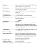
Display: ............................High-contrast Film SuperTwist LCD. Diagonal viewing area: 3.5" (8.9 cm). Resolution: ......................240 pixels (vert.) x 160 pixels (horiz.) resolution; 38,400 total pixels Backlighting: ..................Amber LED backlit screen and keypad for night use. Input power: ...................10 to 17 volts DC. Current drain: ................170 ma lights off; 240 ma lights on. Back-up memory:...........Built-in memory stores sonar settings when unit is turned off.
Auto bottom track: ........Yes. Zoom bottom track:.......Yes. Split-screen zoom: .........Yes. Surface water temp: .....Yes, built into transducer. Optional external temperature sensor or combo speed/temp sensor available. Speed/distance log: .......Yes, with optional speed sensor. This manual covers the FishEasy 240 and FishEasy 240 Portable. Both units operate the same way.
The transmitter emits an electrical impulse, which the transducer converts into a sound wave and sends into the water. (The sound frequency can't be heard by humans or fish.) The sound wave strikes an object (fish, structure, bottom) and bounces back to the transducer, which converts the sound back into an electrical signal. The receiver amplifies this return signal, or echo, and sends it to the display, where an image of the object appears on the scrolling sonar chart.
Transducer Installation Preparations The following shows the recommended sequence for installing the transducer: CAUTION: You should read over this entire installation section before drilling any holes in your vehicle or vessel! 1. Determine the approximate location for the sonar unit, so you can plan how and where to route the cables for the transducer and power. This will help you make sure you have enough cable length for the desired configuration. 2.
trolling motor mount uses a one-piece plastic bracket with an adjustable strap. These are all "kick-up" mounting brackets. They help prevent damage if the transducer strikes an object while the boat is moving. If the transducer does "kick-up," the bracket can easily be pushed back into place without tools. Depending on your sonar unit's connectors, your transducer cable may also have the sonar unit's power cable attached to it.
Single-frequency trolling motor installations Tools: two adjustable wrenches, flat-head screwdriver. Supplies: plastic cable ties. Shoot-through hull installations Tools: these will vary depending on your hull's composition. Consult your boat dealer or manufacturer. Supplies: 100 grit sandpaper, specially formulated epoxy adhesive available from LEI (see ordering information on the inside back cover). A sandwich hull also requires polyester resin. Selecting a Transducer Location 1.
Deadrise less than 10° Strakes Pad Left, vee pad hull; right, vee hull. A pod style transducer is shown here, but the principle is the same for Skimmers inside a hull. 4. If the transducer is mounted on the transom, make sure it doesn't interfere with the trailer or hauling of the boat. Also, don't mount it closer than approximately one foot from the engine's lower unit. This will prevent cavitation (bubble) interference with propeller operation. 5.
How low should you go? For most situations, you should install your Skimmer transducer so that its centerline is level with the bottom of the boat hull. This will usually give you the best combination of smooth water flow and protection from bangs and bumps. Transducer centerline Transom Hull bottom Align transducer centerline with hull bottom. However, there are times when you may need to adjust the transducer slightly higher or lower.
tion (often called simply "thru-hull"). In that case, a hole is cut in the hull and a specially designed transducer is mounted through the hull with a threaded shaft and nut. This puts the transducer in direct contact with the water. Typically, shoot-thru-hull installations give excellent high speed operation and good to excellent depth capability. There is no possibility of damage from floating objects. It can't be knocked off when docking or loading on the trailer.
the metal bracket. This position sets the transducer's coarse angle adjustment for a 14° transom. Most outboard and stern-drive transoms have a 14° angle. Dot Align plastic ratchets in bracket. 2. Aligning the transducer on the transom. Slide the transducer between the two ratchets. Temporarily slide the bolt though the transducer assembly and hold it against the transom. Looking at the transducer from the side, check to see if it will adjust so that its face is parallel to the ground.
Ratchets Insert bolt and check transducer position on transom. 3. Assembling the transducer. Once you determine the correct position for the ratchets, assemble the transducer as shown in the following figure. Don't tighten the lock nut at this time. Nut Metal washer Rubber washers Metal washer Bolt Assemble transducer and bracket.
4. Drilling mounting holes. Hold the transducer and bracket assembly against the transom. The transducer should be roughly parallel to the ground. The transducer's centerline should be in line with the bottom of the hull. Don't let the bracket extend below the hull! Mark the center of each slot for the mounting screw pilot holes. You will drill one hole in the center of each slot. Drill the holes. Use the #29 bit (for the #10 screws).
Route cable over bolt and through bracket. Side view shown at left and seen from above at right. Attach the transducer to the transom. Slide the transducer up or down until it's aligned properly with the bottom of the hull as shown in the preceding and following figures. Tighten the bracket's mounting screws, sealing them with the caulking compound. Adjust the transducer so that it's parallel to the ground and tighten the nut until it touches the outer washer, then add 1/4 turn.
Bottom of hull Deep-"vee" hull Flat-bottom hull Align transducer centerline with hull bottom and attach to transom. 6. Route the transducer cable through or over the transom to the sonar unit. Make sure to leave some slack in the cable at the transducer. If possible, route the transducer cable away from other wiring on the boat. Electrical noise from the engine's wiring, bilge pumps, VHF radio wires and cables, and aerators can be picked up by the sonar.
located above the waterline. After installation, be sure to seal the hole with the same marine grade above- or below-waterline sealant used for the mounting screws. 7. Make a test run to determine the results. If the bottom is lost at high speed, or if noise appears on the display, try sliding the transducer bracket down. This puts the transducer deeper into the water, hopefully below the turbulence causing the noise.
3. Route the transducer cable alongside the trolling motor shaft. Use plastic ties (not included) to attach the transducer cable to the trolling motor shaft. Make sure there is enough slack in the cable for the motor to turn freely. Route the cable to the sonar unit and the transducer is ready for use. Transducer mounted on trolling motor, side view.
Partial fish arches Transducer aimed too far forward Transducer aimed too far back Full fish arch Proper transducer angle Transducer angles and their effects on fish arches. If the arch slopes up – but not back down – then the front of the transducer is too high and needs to be lowered. If only the back half of the arch is printed, then the nose of the transducer is angled too far down and needs to be raised.
NOTE: Periodically wash the transducer's face with soap and water to remove any oil film. Oil and dirt on the face will reduce the sensitivity or may even prevent operation. Shoot-Thru-Hull Preparation Hulls With Flotation Materials The transducer installation inside a fiberglass hull must be in an area that does not have air bubbles in the resin or separated fiberglass layers. The sonar signal must pass through solid fiberglass.
For example, some (but not all) manufacturers use a layer of fiberglass, then a core of balsa wood, finishing with an outer layer of fiberglass. Removing the inner layer of fiberglass and the balsa wood core exposes the outer layer of fiberglass. The transducer can then be epoxied directly to the outer layer of fiberglass. After the epoxy cures for 24 hours, fill the remaining space with polyester resin. When the job is finished, the hull is watertight and structurally sound.
(more rocky) the bottom, the easier it will be to get a second bottom signal.) Don't touch the controls once they've been set. True bottom Second bottom Manual range setting Example of a second bottom signal. Unit is in 30 feet of water, with range set at 80 feet and sensitivity set at 87 percent. 2. Next, take the transducer out of the water and place it in the water in the sump of the boat, face down. (The transducer face is shown in the figure on the following page.
hull. This is especially true if you have to turn sensitivity all the way up to get a decent bottom signal. 4. Most people can get good results by following steps 1 through 3, so this step is optional. If you want to make an extra effort to be absolutely sure that your selected location will work under all conditions, make a test run with the boat on plane and observe the bottom signal. You'll need to figure some way to prop the transducer into position while you make your test run.
Spread epoxy here Sand this surface Orient the Skimmer with the nose facing the bow of the boat. To bow Epoxy transducer to hull. WARNING: Use only the epoxy available from LEI. It has been formulated to work with these installation procedures. Other epoxy types may be too thin or may not cure to the right consistency for optimum transducer performance. 2. The epoxy consists of the epoxy itself and a hardener. Remove the two compounds from the package and place them on the paper plate.
air pockets in the epoxy layer! Then, apply the remaining epoxy to the sanded area on the hull. 3. Press the transducer into the epoxy, twisting and turning it to force any air bubbles out from under the transducer face. Stop pressing when you bottom out on the hull. When you're finished, the face of the transducer should be parallel with the hull, with a minimum amount of epoxy between the hull and transducer. 4. Apply a weight, such as a brick, to hold the transducer in place while the epoxy cures.
Speed/Temperature Sensors The FishEasy 240 family can accept as many as two temperature sensors, which can be used to monitor the temperature of surface water, a live well or some other location. These units can accept an optional speed sensor for showing speed and distance traveled. However, you can only use one accessory at a time. If you would like to use a speed sensor and a temperature sensor at the same time, you will need a combination device.
See the following charts for sample sensor combinations and cable connections. Sonar unit rear view ST-TU combination speed and temperature sensor 3-amp fuse 12-volt battery Power/transducer cable Temperature sensor built into transducer HST-WSU Sonar unit with external combination speed and temperature sensor. Primary temp sensor is built into transducer.
Sonar unit rear view TS-2U temperature sensor 3-amp fuse 12-volt battery Power/transducer cable Temperature sensor built into transducer HST-WSU Sonar unit with secondary external temperature sensor. Primary temp sensor is built into transducer.
Sonar unit rear view SP-U speed-only sensor 3-amp fuse 12-volt battery Power/transducer cable Temperature sensor built into transducer HST-WSU Sonar unit with external speed sensor. Temp sensor is built into transducer. Speed Sensor Installation If you wish to purchase an optional sensor for your unit, refer to the accessory ordering information inside the back cover of this manual. The following instructions describe how to install the speed sensor.
First find a location on the boat's transom where the water flow is smoothest. Don't mount the sensor behind strakes or ribs. These will disturb the water flow to the speed sensor. Make sure the sensor will remain in the water when the boat is on plane. Also make sure the location doesn't interfere with the boat's trailer. Typically, the sensor is mounted about one foot to the side of the transom's centerline. Once you've determined the proper location for the unit, place the sensor on the transom.
Transom Bottom of hull Bottom of hull Speed sensor mounting configuration: side view (left) and rear view (right.) If the base of the transom has a radius, fill the gap between the transom and the sensor with the caulking compound. This will help ensure a smooth water flow. Route the sensor's cable through or over the transom to the sonar unit. If you need to drill a hole in the transom to pass the connector through, the required hole size is 5/8".
interference, attach the power cable directly to the battery. If the cable is not long enough, splice #18 gauge wire onto it. CAUTION: When using the unit in a saltwater environment, we strongly recommend that you shut off the power supply to the power cable when the unit is not in use. When the unit is turned off but still connected to a power supply, electrolysis can occur in the power cable plug.
If possible, keep the power cable away from other boat wiring, especially the engine's wires. This will provide the best isolation from electrical noise. The power cable has two wires, red and black. Red is the positive lead, black is negative or ground. Make sure to attach the inline fuse holder to the red lead as close to the power source as possible. For example, if you have to extend the power cable to the battery or power buss, attach one end of the fuse holder directly to the battery or power buss.
Mount the unit in any convenient location, provided there is clearance when it’s tilted for the best viewing angle. You should also make sure there is enough room behind the unit to attach the power/transducer cable. (See the following drawings, which show the dimensions of a gimbal-mounted FishEasy 240 sonar unit.) Holes in the bracket’s base allow wood screw or through-bolt mounting.
82.7 [3.26] 107.5 [4.23] 156 [6.26] 12.09 [0.48] 76.9 [3.03] Millimeter [Inch] 70.3 [2.77] Front view (left) and side view (right) showing dimensions of the FishEasy 240 when mounted on quick release bracket. After drilling the hole, pass the connectors up through the hole from under the dash. If you wish, you can fill in the hole around the cable with a good marine caulking compound. (Some marine dealers stock cable hole covers to conceal the opening.
Align the bracket over the cable hole with the cable slots facing away from you and fit the cable through one of the slots. Fasten the bracket to the dash using the three screw holes. Ratchet Rear (away from viewer) Screw hole Power/transducer cable Cable slot FishEasy 240 quick release mounting bracket. Slots in the base allow routing the cable from beneath the mount. Attach the unit to the bracket by first connecting the power/transducer and accessory cables.
Bracket front Mount the sonar: slide the unit onto the bracket from above. Depress ratchets to release Adjust viewing angle: use one hand to press and release the springloaded ratchets while you move the unit with the other hand.
Portable Sonar Installation Like many Eagle products, the FishEasy 240 sonar is capable of portable operation. It uses the optional PPP-12 portable power pack. The power pack and portable transducers expand the uses for your sonar. You can use your FishEasy 240 sonar unit on your boat or take it to the dock, on a float tube, on an ice fishing trip or use it as a second sonar in a friend's boat. The PPP-12 package includes the power pack, battery adapter and a portable transducer.
PPP-12 Portable Power Pack with FishEasy 240 stowed for transport. Turn the sonar unit on. If it doesn't work, make sure the battery terminals are making good contact against the battery contacts. Also check the wiring connections on the battery adapter. The red wire on the power cable should be attached to the red wire on the battery adapter and the power cable's black wire should be connected to the black wire on the battery adapter. If it still doesn't work, check the battery voltage.
Portable Transducer Assembly Recommended tools for installation include a slotted screw driver and two adjustable wrenches. Assemble the transducer and bracket as shown in the following figure. Attach the transducer to the bracket with the supplied hardware. Make sure there is one washer on each side of the transducer, inside the bracket. Slide the other washer over the end of the bolt and thread the nut onto it. Screw the suction cup onto the bracket using the supplied screw and flat washer.
allow the bracket to extend below the hull, because water pressure against it can cause the suction cup to come off at speed. Moisten the cup, then press it onto the hull as firmly as possible. Tie the nylon cord to the boat and route the transducer cable to the sonar unit. Your portable sonar is now ready for use. Suction cup Bracket Hull Transducer Portable transducer installed on boat transom.
Operation Keyboard Basics The unit sounds a tone when you press any key. This tells you the unit has accepted a command. Numbers in the figure correspond to key explanations below: 2 3 1 Eagle FishEasy 240 Sonar, showing screen and keyboard. 1. PWR/CLEAR (power and clear) This key appears in the manual text simply as PWR. Press this key to turn the unit on and off. It also clears menu selections and the menus from the screen.
3. MENU DOWN (menu down) These keys appears in the manual text as MENU UP or MENU DOWN. Most of the time, the instructions require you to press either menu key, so the text simply uses the word MENU. Usually, when we say MENU, you can simply press the MENU UP key for consistency. This sonar unit has many features that are accessed with the menu keys. The MENU UP key moves up or forward through the menus, the MENU DOWN key moves down or backward. To see the first menu, simply press either MENU key.
Menu This screen shows a typical menu, the Scroll Speed menu. Display – Opening Screen The lights flash for about 10 seconds when the unit is turned on. The backlight menu first appears on the screen. To turn the lights on, press UP ARROW. If you don’t press a key, the menu will disappear after a few seconds. If you don't want to wait, press PWR to clear the menus from the screen.
Digital depth Surface clutter School of bait fish Fish arches near bait fish Thermocline Depth scale Grayline Bottom signal Depth range at bottom of depth scale Speed Opening screen, Full Chart page, or mode. Chart Scroll (stopping and starting) In normal operation, the sonar chart will scroll from right to left across the screen. You can stop the chart from scrolling across the screen. This is useful when you want to "freeze" the picture to study it more closely.
Chart menu. Chart is running or scrolling normally at left. Chart is stopped at right, and "Stopped" warning message appears. Screen Display Modes or Pages The FishEasy 240 has three screen display modes, or "Pages:" Full Chart page, Split Chart page and Large Digital page. The FishEasy 240 Page menu lets you select among the display modes, or pages. To switch from one page to another page, press MENU until the PAGE menu appears.
page. (The screen changes as you move through the menu.) When the page you want is selected, press PWR to clear the menu. Full Chart This shows all echoes scrolling across the full screen. This is the default page. The bottom signal scrolls across the screen from right to left. Depth scales on the right side of the screen make it easy to determine the depth of fish, structure, and other targets. The line at the top of the screen represents the surface.
Split Chart page with normal view at right; zoomed view at left. Lrg Digital (Large Digital) The Large Digital page shows all information in big numbers. The digital depth display is at the top of this screen, followed by the temperature, speed, and distance readings. NOTE: Temperature, speed, and distance require a temperature or speed sensor. These may be optional equipment, depending on the sonar model you purchased. Large Digital page.
Range When turned on for the first time, the unit automatically adjusts the depth range according to water conditions. It always keeps the bottom displayed in the lower portion of the screen. You can over-ride the automatic range control and manually select a range. To do this, press MENU until the RANGE menu appears. Use the arrow keys to select the desired range. When you're finished, press PWR to clear the menu from the display. Range Select menu.
Zoom screen, showing Zoom menu and the 2X zoom indicator at the top right of the screen. To zoom the display, first press the MENU key until the ZOOM menu appears. Use the arrow keys to select either 2X or 4X zoom, then press PWR to clear the menu. When the display is in Zoom mode, the screen will show a zoom indicator box at the top right corner of the screen. This is a reminder that the display is zoomed, and it tells what level of zoom is in effect.
Fig. 1 Fig. 2 Fig. 3 In 34 feet of water, with the Range set manually at 60 feet, the unit shows the entire water column in Fig. 1. To get a closer look, turn around and follow your wake to troll over the structure again. With the unit in 4X zoom, press the down arrow key to look at the six fish along the ledge, then press the up arrow to pan up the water column to see four game fish threatening a school of forage fish.
Sensitivity Sensitivity controls the unit's ability to pick up echoes. If you want to see more detail, try increasing the sensitivity, a little at a time. There are situations when too much clutter appears on the screen. Decreasing the sensitivity can reduce the clutter and show the strongest fish echoes, if fish are present. As you change the sensitivity setting, you can see the difference on the chart as it scrolls.
Bait school Thermocline with fish Fish arches Fig. 1 Fig. 2 Fig. 3 Fig. 4 These figures show results of different sensitivity levels on the same location. Fig. 1: Sensitivity at 87 percent, determined by Auto Sensitivity. Typical of full auto mode. Fig. 2: Sensitivity set at 50 percent. Fig. 3: Sensitivity set at 20 percent. Fig. 4: Sensitivity set at 100 percent. You can change the sensitivity level whether you are in Auto Sensitivity mode or Manual Sensitivity mode.
Adjusting sensitivity in Auto Sensitivity Mode is similar to manually adjusting a car's speed with the accelerator pedal while cruise control is on. You can tell the car to run faster, but when you let off the gas the cruise control automatically keeps you from running slower than the minimum speed setting. In your unit, auto mode will let you increase sensitivity to 100 percent, but the unit will limit your minimum setting.
To adjust sensitivity: Press MENU until the SENSITIVITY ADJUSTMENT menu appears. Press UP ARROW to increase the sensitivity, DOWN ARROW to decrease it. When it's set at the desired level, press PWR to clear the menu. The sensitivity percentage in use shows in this menu. As you change the setting, echoes scrolling onto the screen will show the effects of the change. If you reach the maximum or minimum sensitivity level, a tone sounds alerting you to the limits.
To change the Grayline level, press MENU until the GRAYLINE menu appears. Press UP ARROW to increase the level or press DOWN ARROW to decrease it. The percentage of Grayline in use shows in this menu. Echoes scrolling onto the screen will also show the effects of the Grayline change. If you reach the maximum or minimum level, a tone sounds alerting you to the limits. Press PWR to clear the menu. Thin or no Grayline Wider Grayline At left, Grayline menu screen.
displays a small fish symbol when it thinks a target is a small fish, a medium fish symbol on a larger target and so forth. Fish I.D. symbol Fish arches At left, underwater scene in normal fish arch mode. Right, Fish I.D. menu with the feature turned on. Fish I.D. is an easier way for a sonar novice to recognize a fishy signal return when he sees it. However, locating fish by symbol only has some limitations. Your sonar unit's microcomputer is sophisticated, but it can be fooled.
out of reading the screen. Remember: Fish I.D. is one of the many tools we provide so you can analyze your sonar returns for maximum fish finding information. This and other features can help you successfully "see" beneath the boat under varied water and fishing conditions. So, practice with the unit in both the Fish I.D. mode and without to become more familiar with the feature. The default for Fish I.D. is off. Fish I.D.
Fish I.D. symbol showing FishTrack depth indicator Fish ID menu and symbol with FishTrack on. The fish is 44 feet deep. FishReveal When displaying actual sonar returns, the FishReveal feature helps show fish targets hidden by surface clutter, thermoclines, weed beds and other cover with 10 levels of gray tones. Normal operation (with FishReveal turned off) shows the weakest echoes as black and the strongest in light gray.
At left FishReveal menu screen. The feature is off and screen is in normal mode. Right, Fish Reveal is on, in standard mode. There are two FishReveal modes: standard and inverted. In standard mode, the weakest echoes are white and the strongest echoes are black. Echoes in between vary in gray in proportion to their signal strength. In Inverted FishReveal mode, the weakest echoes are black and the strongest echoes are white. Again, echoes in between vary in gray in proportion to their signal strength.
To turn FishReveal on, press MENU DOWN until CHART SETUP appears, then press UP ARROW. Press MENU DOWN until CHART MODE appears. Press DOWN ARROW to select the desired FishReveal mode. Press PWR to clear the menu. To return to normal operation, repeat the above steps, but select NORMAL before clearing the menu. Chart Scroll Speed and HyperScroll The rate that echoes scroll across the screen is called the chart scroll speed.
At right, Scroll Speed menu at default 60 percent setting. At left, Scroll Speed menu, with unit set to HyperScroll mode. If you are running fast, try a HyperScroll setting of 80 to 100 percent. When using HyperScroll, you may also need to manually decrease the sensitivity for best performance. Depending on water conditions, HyperScroll may cause a second bottom echo and large amounts of clutter to appear on the screen. If this occurs, just decrease the sensitivity to a level that eliminates the clutter.
ASP is an effective tool in combating noise. In sonar terms, noise is any undesired signal. It is caused by electrical and mechanical sources such as bilge pumps, engine ignition systems and wiring, air bubbles passing over the face of the transducer, even vibration from the engine. In all cases, noise can produce unwanted marks on the display.
Alarms The sonar unit has two different types of alarms, fish and depth. Fish Alarm The Fish Alarm sounds a tone when a fish symbol appears on the screen. The default setting is on, but the Fish I.D. feature must be turned on for fish alarms to work. To turn Fish I.D. on, press MENU until the FISH ID menu appears. Press UP ARROW to select ON, then press PWR. To turn off the fish alarm without turning off fish symbols, press MENU DOWN until FISH ALARM appears.
Shallow Alarm To set the shallow alarm depth, press MENU DOWN repeatedly until SHALLOW ALARM appears. Shallow Alarm menu. Press UP ARROW to increase the shallow alarm's depth setting or press DOWN ARROW to decrease it. The number in the shallow alarm’s menu box shows the current shallow alarm setting. When the number reaches the desired setting, press PWR to clear the menu. When the bottom depth goes shallower than the alarm’s setting, an alarm tone sounds and a message box appears on the screen.
shows the current deep alarm setting. When the number reaches the desired setting, press PWR to clear the menu. When the bottom depth goes deeper than the alarm’s setting, an alarm tone sounds and a message box appears on the screen. Deep Alarm menu. Press UP ARROW to silence the alarm. This turns the alarm sound off until the deep alarm is triggered again. To turn the alarm off, press MENU DOWN repeatedly until DEEP ALARM appears.
System Setup menu. Display Adjustments Backlights The display is backlit for night use. To turn the backlight on or off, press MENU repeatedly until the BACK LIGHT menu appears. Press UP ARROW to turn the light on or the DOWN ARROW to turn it off. Backlight menu.
Display Contrast The unit’s display contrast is adjustable to suit different lighting conditions. This will help you see the screen from different angles or at various times of the day. The default setting is 50 percent. To adjust the contrast, press MENU DOWN until the SYSTEM menu appears, press UP ARROW, and the CONTRAST menu appears. To decrease screen contrast, press the DOWN ARROW key. Press the UP ARROW key to increase screen contrast.
Depth menu controls the unit of measure used to show depth. Temperature Units of Measure This unit can show the temperature (if a temperature sensor is attached) in degrees Fahrenheit or Celsius. To change the unit of measure, press MENU DOWN until the SYSTEM menu appears. Press UP ARROW, then press MENU until the TEMPERATURE menu appears. Use the arrow keys to select the measurement unit, then press PWR to clear the menu. Temperature unit of measure menu.
Speed and Distance Log Units of Measure The speed and distance log can be displayed in statute miles (MPH), Nautical miles (knots), or Metric (kilometers per hour) if a speed sensor is attached. To change the unit of measure, press MENU DOWN until the SYSTEM menu appears. Press UP ARROW, then press MENU until the SPEED/LOG menu appears. Use the arrow keys to select the desired measurement unit, then press PWR to clear the menu. Speed menu.
Reset Log menu. Preset Unit (reset all options) This command is used to reset all features, options and settings to their original factory defaults. This is useful when you have changed several settings and want to return the unit to basic automatic operation. Press MENU DOWN until SYSTEM appears, then press UP ARROW. Press MENU DOWN until the PRESET UNIT menu appears. Press UP ARROW and the unit will turn itself off and reset all options. Turn the unit back on by pressing PWR.
System Info To show the operating software system information, press MENU DOWN until the SYSTEM menu appears, then press UP ARROW. Press MENU DOWN until the SYSTEM INFO screen appears. Press PWR to clear the screen. System Info screen. Simulator This unit has a built-in simulator that shows a simulated bottom signal with fish signals. This lets you practice with the unit as if you were on the water; all features and functions of the unit are usable.
Simulator menu. NOTE: If you turn on your unit before attaching a transducer, it may enter a demo mode. The words "demo mode" flash on the bottom of the screen and a sonar chart plays much like the simulator. Unlike the simulator, the demo mode is for demonstration only, and will automatically stop as soon as you turn on the unit with a transducer attached. The simulator will continue to function normally. Chart Setup The Chart Setup menu lets you further customize the display.
Chart Setup menu. Limit Search The Limit Search command helps you maintain maximum chart detail when you are moving fast in deep water (about 200 feet). When turned on, Limit Search prevents the digital sonar from over-riding the sonar chart's depth range setting. Limit Search does this by preventing the digital sonar from slowing down the ping speed as it automatically searches for and tracks the bottom. The default setting is off, and this should fit most freshwater fishing situations.
The sonar chart must be in manual depth range mode to use the Limit Search command. To switch from auto depth range to manual, press MENU until the RANGE menu appears. Use the arrow keys to select the desired range. When you're finished, press PWR to clear the menu from the display. Next, press MENU DOWN until the CHART SETUP menu appears, then press UP ARROW to enter the list of Chart Setup commands, where the LIMIT SEARCH menu appears. Press UP ARROW to turn it on and press PWR to clear the menu.
To change any of these options, press MENU DOWN until CHART SETUP appears, then press UP ARROW. Use the MENU keys to cycle through the list and display the desired menu, then use the ARROW keys to select the desired number size or turn the numbers off. Press the PWR key to clear the menus. Menus for changing digital number size. Scales The depth scale between the upper and lower limit on the right side of the screen can be turned on or off. The default is on.
Scales menu, with scale on (left) and off (right). With the scale off, only the upper and lower limits (zero and 60 in this case) are displayed To turn the scale off, press MENU DOWN until CHART SETUP appears, then press UP ARROW. Press MENU DOWN until SCALES appears, then press DOWN ARROW to select UPPER LOWER ONLY. Press the PWR key to clear the menus. To turn scale on, press MENU DOWN until CHART SETUP appears, then press UP ARROW.
Troubleshooting If your unit is not working, or if you need technical help, please use the following troubleshooting section before contacting the factory customer service department. It may save you the trouble of returning your unit for repair. For contact information, refer to the last page, just inside the back cover of this manual. Unit won't turn on: 1. Check the power cable's connection at the unit. Also check the wiring. 2. Make certain the power cable is wired properly.
Weak bottom echo, digital readings erratic, or no fish signals: 1. Make sure the transducer is pointing straight down. Clean the face of the transducer. Oil, dirt and fuel can cause a film to form on the transducer, reducing its effectiveness. If the transducer is mounted inside the hull, be sure it is shooting through only one layer of fiberglass and that it is securely bonded to the hull.
2. Electrical noise from the boat's motor can interfere with the sonar. This causes the sonar to automatically increase its Discrimination or noise rejection feature. This can cause the unit to eliminate weaker signals such as fish or even structure from the display. Try using resistor spark plugs or routing the sonar unit's power and transducer cables away from other electrical wiring on the boat. No fish arches when the Fish I.D. feature is off: 1. Make certain the transducer is pointing straight down.
Sensitivity should be set at 90-95 percent. There should be a steady bottom signal on the display. Now turn on each piece of electrical equipment on the boat and view the effect on the sonar's display. For example, turn on the bilge pump and view the sonar display for noise. If no noise is present, turn the pump off, then turn on the VHF radio and transmit. Keep doing this until all electrical equipment has been turned on, their effect on the sonar display noted, then turned off.
Index A Accessories, 5, 35, 36 Alarms, 60 Depth Alarms, 61 Fish Alarm, 61 Antenna, 78 ASP (Advanced Signal Processing), 24, 59 I Installation, 9, 26, 31, 35, 36, 37, 38 Introduction Specifications, 5 P Page Displays, 44 Digital Data, 72 Ping Speed HyperScroll, 58 Power, 6, 9, 10, 33, 34, 35, 36, 37, 38, 39, 40, 41, 53, 75, 76, 77, 78 Product Specifications, 5 B Backlights / Lighting, 6, 64 Batteries, 9, 10, 33, 34, 38, 41, 75, 76, 78 C Contrast, 6, 63, 64, 65 R Range, 24, 25, 42, 46, 47, 48, 49, 57, 71
T Temperature Sensors, 7, 14, 19, 28, 29, 30, 31 Transducer, 5, 6, 7, 9, 10, 11, 12, 13, 14, 15, 16, 17, 18, 19, 20, 21, 22, 23, 24, 25, 26, 27, 29, 30, 31, 36, 37, 38, 60, 70, 75, 76, 77, 78 Mounting, 14, 20 Shoot-Thru-Hull, 23 U Units of Measure, 65, 66, 67 Z Zooming, 7, 47, 48, 49, 77 Zoom Pan, 48 82
EAGLE ELECTRONICS FULL ONE-YEAR WARRANTY "We," "our," or "us" refers to EAGLE ELECTRONICS, a division of LEI, the manufacturer of this product. "You" or "your" refers to the first person who purchases this product as a consumer item for personal, family, or household use. We warrant this product against defects or malfunctions in materials and workmanship, and against failure to conform to this product's written specifications, all for one (1) year from the date of original purchase by you.
How to Obtain Service… …in the USA: We back your investment in quality products with quick, expert service and genuine Eagle replacement parts. If you're in the United States and you have technical, return or repair questions, please contact the Factory Customer Service Department. Before any product can be returned, you must call customer service to determine if a return is necessary. Many times, customer service can resolve your problem over the phone without sending your product to the factory.
Accessory Ordering Information for all countries To order Eagle accessories such as power cables or transducers, please contact: 1) Your local marine dealer or consumer electronics store. Most quality dealers that handle marine electronic equipment or other consumer electronics should be able to assist you with these items. To locate an Eagle dealer near you, visit our web site, and look for the Dealer Locator (www.eaglesonar.com/Products/HowToBuy/dealers.asp).
Visit our web site: www.eaglesonar.com Eagle Pub.