Pub. 988-0152-151 www.eaglesonar.
Copyright © 2005 LEI-Eagle All rights reserved. No part of this manual may be copied, reproduced, republished, transmitted or distributed for any purpose, without prior written consent of Eagle Electronics. Any unauthorized commercial distribution of this manual is strictly prohibited. Eagle® is a registered trademark of LEI. MapCreate, FreedomMaps and NauticPath are trademarks of LEI. Fishing Hot Spots is a registered trademark of Fishing Hot Spots Inc.
Table of Contents Section 1: Read Me First! ......................................................... 1 Capabilities and Specifications: .................................................... 3 How Eagle Sonar Works............................................................... 5 How GPS Works............................................................................ 6 Introduction to GPS and WAAS................................................... 7 Free Training Aids Available ..............................
Pages ........................................................................................... 42 Satellite Status Page .............................................................. 42 Navigation Page ...................................................................... 43 Map Page................................................................................. 43 Sonar Page .............................................................................. 44 Basic Sonar Quick Reference ...................
Stop Chart ................................................................................... 78 Surface Clarity ............................................................................ 78 Zoom & Zoom Bar ....................................................................... 79 Zoom Pan..................................................................................... 80 Section 5: Sonar Troubleshooting ....................................... 81 Section 6: Basic GPS Operations ......................
Create Icon on Map............................................................... 118 Create Icon at Current Position ........................................... 118 Delete an Icon ....................................................................... 118 Navigate to an Icon ............................................................... 119 Routes........................................................................................ 119 Create and Save a Route ............................................
Earth Map Detail .................................................................. 141 Pop-up Map Information ...................................................... 142 Draw Map Boundaries.......................................................... 142 Fill Water With White .......................................................... 142 Map Overlays (Range Rings; Lat/Long Grid) ...................... 142 Map Datum Selection ...............................................................
WARNING! A CAREFUL NAVIGATOR NEVER RELIES ON ONLY ONE METHOD TO OBTAIN POSITION INFORMATION. CAUTION When showing navigation data to a position (waypoint), a GPS unit will show the shortest, most direct path to the waypoint. It provides navigation data to the waypoint regardless of obstructions.
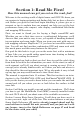
Section 1: Read Me First! How this manual can get you out on the road, fast! Welcome to the exciting world of digital sonar and GPS! We know you are anxious to begin navigating and finding fish, but we have a favor to ask. Before you grab the unit and begin installing it, please give us a moment or two to explain how our manual can help you get the best performance from your compact, color display, combination fish finder and mapping GPS receiver.
After you have gained some experience with your sonar, you will want to check out Section 4, which discusses more advanced Sonar Options and Other Features. When you come to a sonar menu command on the unit's screen, you can look it up in the manual by skimming over the table of contents, just flipping through Section 3 or scanning through the sonar options in Section 4. If you're having difficulty with your sonar, you can find an answer to the most common problems in Section 5, Sonar Troubleshooting.
It's important to us and our power users, but if you don't care how many watts of power the unit has or how many waypoints it can store, skip ahead to important information on how sonar works on page 5. Background on GPS begins on page 6. Capabilities and Specifications: General Display:............................ 5.0" (12.7 cm) diagonal 256-color enhanced TFT LCD; programmable to viewing preference. Resolution:...................... 640 pixel x 480 pixel resolution; 307,200 total pixels. Backlighting....
Sonar Sounding Depth capability:........... SeaCharter 642cDF iGPS: 1,500 feet (457 meters). FishElite 642c iGPS: 800 feet (244 meters). Actual capability depends on transducer configuration and installation, bottom composition and water conditions. All sonar units typically read deeper in fresh water than in salt water. Depth display:................ Continuous display . Audible alarms: ............. Deep/shallow/fish/zone. Automatic ranging:....... Yes, with instant screen updates. Auto bottom track:.....
Position points: ............. 1,000 waypoints; 1,000 event marker icons. Audible alarms: ............. Arrival/off-course/anchor. Graphic symbols for waypoints or event marker icons: ................. 42. Routes:............................. 100, up to 100 waypoints per route. Plot Trails: ...................... 10 savable; up to 10,000 points per trail. Zoom range:.................... 40 ranges; 0.02 to 4,000 miles. NOTE: The above memory capacities refer only to the unit’s on-board memory.
chart. The sonar's microprocessor calculates the time lapse between the transmitted signal and echo return to determine the distance to the object. The whole process repeats itself several times each second. Your unit can record a log of the sonar signals that scroll across the screen and save them to the MMC memory card. (These recordings are also called sonar charts or sonar graphs.
making software, MapCreate 6 or one of our special plug-and-play mapping cards. Some unit features — such as searching for businesses and addresses — won't work without a custom MapCreate map. There is so much detail in our background map (and even more in MapCreate) that we'll describe their contents and differences in Section 3, Basic GPS Operations, on page 94.
so you can mount your unit and plug in the power. Or you might want to see how our text formatting makes the manual tutorials easy to skim. If that's the case, move on to How to Use This Manual on page 11. But, if you want to understand the current state of satellite navigation, look over this segment describing how GPS and its new companion WAAS work together to get you where you're going. The Global Positioning System (GPS) was launched July 17, 1995 by the United States Department of Defense.
Remember, the unit must have a clear view of the satellites in order to receive their signals. Unlike radio or television signals, GPS works at very high frequencies. These signals can be easily blocked by trees, buildings, an automobile roof, even your body. Like most GPS receivers, this unit does not have a compass or any other navigation aid built inside. It relies solely on the signals from the satellites to calculate a position.
of terrain! It only calculates position, it can’t know what’s between you and your destination, for example. It’s up to you to safely navigate around obstacles, no matter how you’re using this product. Free Training Aids Available Now that you know something about the technology that makes this unit possible, you are ready to start learning how to use that technology! This manual will guide you through the process of setting up and running your unit, but that is only one of many resources available.
The emulator works exactly like your real sonar/GPS unit. When using the Sonar and GPS Simulators you can play back sonar logs, run GPS routes and trails, even create real waypoints you can use in the field. You can take snapshots of the Sonar Chart and print them or e-mail them to friends. And that is just some of the material available on our web site. To find out what we have available, go to WWW.EAGLESONAR.COM and look around. For now, we'll get back to how to use this particular unit.
For example, instructions for navigating a trail would look like this: 1. From the Map Page, press MENU|MENU|↓ to MY TRAILS|ENT. 2. Press ↓ to Trail 1|ENT|→ to NAVIGATE|ENT. 3. You are asked to wait while it converts the trail into a route. 4. The wait message disappears and the unit begins showing navigation information along the trail. Now, begin moving and follow your unit's directions. Translated into complete English, step 1 above would mean: "Start on the Map Page. Press the Menu key twice.
Section 2: Installation & Accessories Preparations You can install the unit in some other order if you prefer, but we recommend this installation sequence: Caution: You should read over this entire installation section before drilling any holes in your vessel! 1. Determine the approximate location for the unit, so you can plan how and where to route the cables for the transducer, any sensor and power. This will help you make sure you have enough cable length for the desired configuration.
Read these instructions carefully before attempting the installation. Determine which of the installation methods is right for your boat. Remember, transducer location is the most critical part of a sonar installation. Recommended Tools and Supplies If you prefer the option of routing the cable through the transom, you will need a 5/8" drill bit. (If you intend to install an additional speed or temp sensor and route its cable through the same hole in the transom, you will need a 1" (25.
NOTE: Some aluminum boats with strakes or ribs on the outside of the hull create large amounts of turbulence at high speed. These boats typically have large outboard motors capable of propelling the boat at speeds faster than 35 mph. Typically, a good transom location on aluminum boats is between the ribs closest to the engine. 3. The transducer should be installed with its face pointing straight down, if possible.
Transom Transom Transducer centerline Hull bottom Hull bottom Align transducer centerline with hull bottom. A dual frequency transducer (left) and a single frequency transducer (right). How low should you go? For most situations, you should install your Skimmer transducer so that its centerline is level with the bottom of the boat hull. This will usually give you the best combination of smooth water flow and protection from bangs and bumps.
The shoot-thru-hull installation does have its drawbacks. First, some loss of sensitivity does occur, even on the best hulls. This varies from hull to hull, even from different installations on the same hull. This is caused by differences in hull lay-up and construction. Second, the transducer angle cannot be adjusted for the best fish arches on your sonar display. (This is not an issue for flasher-style sonars.
Dot Align plastic ratchets in bracket. B. Two-piece bracket: Locate the four plastic ratchets in the transducer's hardware package. Press two ratchets into the sides of the plastic bracket and two on either side of the transducer as shown in the following illustrations. Notice there are letters molded into each ratchet. Place the ratchets into the bracket with the letter "A" aligned with the alignment mark molded into the bracket.
2. Aligning the transducer on the transom. A. One-piece bracket: Slide the transducer between the two ratchets. Temporarily slide the bolt though the transducer assembly and hold it against the transom. Looking at the transducer from the side, check to see if it will adjust so that its face is parallel to the ground. If it does, then the "A" position is correct for your hull. If the transducer's face isn't parallel with the ground, remove the transducer and ratchets from the bracket.
If the transducer's face isn't parallel with the ground, remove and disassemble the transducer and ratchets. Place the ratchets into the bracket holes with the letter "B" aligned with the bracket alignment mark. Place them on the transducer aligned with the 12 o'clock position on the transducer stem. Reassemble the transducer and bracket and place them against the transom. Again, check to see if you can move the transducer so it's parallel with the ground. If you can, then go to step 3B.
Transom Transom Position transducer mount on transom and mark mounting holes. Side view shown (left) and seen from above (right). 5. Attaching transducer to transom. A. One-piece bracket: Remove the transducer from the bracket and reassemble it with the cable passing through the bracket over the bolt as shown in the following figures. For single-frequency Skimmer, route cable over bolt and through bracket. Side view shown (left) and seen from above (right).
6. Route the transducer cable through or over the transom to the sonar unit. Make sure to leave some slack in the cable at the transducer. If possible, route the transducer cable away from other wiring on the boat. Electrical noise from the engine's wiring, bilge pumps, VHF radio wires and cables, and aerators can be picked up by the sonar. Use caution when routing the transducer cable around these wires. WARNING: Clamp the transducer cable to the transom close to the transducer.
3. Route the transducer cable alongside the trolling motor shaft. Use plastic ties (not included) to attach the transducer cable to the trolling motor shaft. Make sure there is enough slack in the cable for the motor to turn freely. Route the cable to the sonar unit and the transducer is ready for use. Transducer mounted on trolling motor, side view.
NOTE: Periodically wash the transducer's face with soap and water to remove any oil film. Oil and dirt on the face will reduce the sensitivity or may even prevent operation. Shoot-Thru-Hull Preparation Hulls With Flotation Materials The transducer installation inside a fiberglass hull must be in an area that does not have air bubbles in the resin or separated fiberglass layers. The sonar signal must pass through solid fiberglass.
Transducer location (high speed) Transducer location (trolling speed) Shoot-thru-hull transducer locations for high speed or trolling speed operation. To choose the proper location for shoot-thru-hull mounting, follow these testing procedures: (You may need a helper to complete these steps.) 1. Anchor the boat in about 30 feet of water. Add a little water to the sump of the boat. Plug the transducer into the sonar unit, turn it on, then hold the transducer over the side of the boat in the water.
The second bottom signal will probably disappear and the bottom signal intensity will likely decrease. 3. Now move the transducer around to find the best location with the strongest possible bottom signal. If you find a spot with an acceptable bottom signal, mark the location and move on to step 4. If you can't get an acceptable bottom signal, try turning up the sensitivity by three or five keystrokes and then move the transducer around once more.
Spread epoxy here Sand this surface (unit's face) Orient the Skimmer with the nose facing the bow of the boat. To bow Epoxy transducer to hull. WARNING: Use only the epoxy available from LEI. It has been formulated to work with these installation procedures. Other epoxy types may be too thin or may not cure to the right consistency for optimum transducer performance. 2. The epoxy consists of the epoxy itself and a hardener. Remove the two compounds from the package and place them on the paper plate.
Leave the weight in place for a minimum of three hours. Allow the epoxy to cure for 24 hours before moving the boat. 5. After the epoxy has cured, route the cable to the sonar unit and it's ready to use. Speed/Temperature Sensors This unit can accept as many as two temperature sensors, which can be used to monitor the temperature of surface water, a live well or some other location. These units can also accept an optional speed sensor for showing speed and distance traveled.
Sonar unit rear view Accessory socket Power/transducer socket Temp sensor Power/transducer cable 3-amp fuse Temp sensor built into transducer Speed or combo speed/temp sensor Sonar unit with external temp sensor, external speed sensor or combo speed/temp sensor. The primary temperature sensor is built into the transducer. Optional Speed Sensor Installation All the units in this series can display speed and distance traveled, but only the SeaCharter 642cDF iGPS comes packed with a speed sensor.
Make sure the location does not interfere with the boat's trailer. Usually, the sensor is mounted about one foot to the side of the transom's centerline. Once you have determined the proper location for the unit, place the sensor on the transom. The bottom of the bracket should be flush with the hull's bottom. Using the sensor as a template, mark the hull for the screw's pilot holes. Drill four 1/8" holes, one in each end of the slots.
The sensor is now ready for use. Connect the sensor to the accessory socket on the back of your unit. If you have any questions concerning the installation of the sensor, please contact your local boat dealer. Power Connections The unit works from a 12-volt battery system. For the best results, attach the power cable directly to the battery. You can attach the power cable to an accessory or power buss, however you may have problems with electrical interference.
To unit Optional power off switch for saltwater installations Black wire 12 volt battery Red wire with 3 amp fuse Power connections for the sonar unit. WARNING: This product must be independently fused with the enclosed 3-amp fuse (or equivalent), even if you connect to a fused accessory or power buss. If a malfunction happens inside the unit, extensive damage can occur if the enclosed fuse is not used.
NMEA format GPS data. The com port can also transmit NMEA format GPS data to another device. A data cable should contain three wires. Com-1 uses the yellow wire to transmit, the orange wire to receive and the shield wire for signal ground. Orange (Receive) Com-1 to unit NMEA Transmit Ground Shield (Ground) To Other GPS Receiver Com-1 wiring to receive NMEA position information from some other GPS receiver.
Optional R-A-M mounting system. Bracket Installation Mount the unit in any convenient location, provided there is clearance behind the unit when it's tilted for the best viewing angle. This must be a location with a clear view of the sky, so the internal GPS antenna can lock-on to the satellite signals. You should also make sure there is enough room behind the unit to attach the power and transducer cables. Holes in the bracket's base allow wood screw or through-bolt mounting.
Drill a 1-inch (25.4 mm) hole in the dash for the power and transducer cables. The best location for this hole is immediately under the gimbal bracket location. This way, the bracket can be installed so that it covers the hole, holds the cables in position and results in a neat installation. Some customers prefer to mount the bracket to the side of the cable hole. It's a matter of personal preference. 77.1 [3.03] 27.6 [1.09] 173.9 [6.85] 137.9 [5.43] 157.9 [6.22] 56.9 [2.
Portable Installation Like many Eagle products, this unit is capable of portable operation by using an optional portable power pack (PPP). The power pack and an optional portable transducer expand the uses for your sonar unit. The PPP makes it easy to use the unit on your boat or take it to the dock, on a float tube, on an ice fishing trip or use it as a second sonar in a friend's boat. Most LEI portable power packs can be used with eight "D" cell alkaline batteries.
The MMC slot is located in a compartment on the front of the case. The compartment door is located at the lower right corner. The following figure shows a close-up with the door opened. Thumb screw Insert card face up, this way Memory card compartment with a 16 MB MMC card installed. To remove an MMC 1. Open the card compartment door by unscrewing the thumb screw. The screw should only be finger tight. If it was over-tightened, use a thumbnail, a coin or a screwdriver to open the door. 2.
MapCreate™ 6 CD-ROM (left). MMC card reader for USB ports (right). NOTE: When you first turn on the unit, the Map Page appears. If you would rather start learning about GPS operation, jump to Sec. 6, Basic GPS Operations. Remember: you don't need to read this manual from cover-to-cover to get going. We designed it so you can skip around to the section you want to read.
Section 3: Basic Sonar Operation This section addresses the unit's most basic sonar operations. The instructions presented in Sec. 3 follow a chronological order. Sec. 4, Sonar Options & Other Features, will discuss other more advanced functions and utilities. Material in Sec. 4 is arranged in alphabetical order. Before you turn on the sonar unit, it is a good idea to learn about the different keys, the Main Menu, the four Page screens and how they all work together.
4. ARROW KEYS – These keys are used to navigate through menus, make menu selections, move the map and sonar chart cursors and enter data. 5. ENT/ICONS – The Enter key allows you to save data, accept values and execute menu commands. It is also used to create event marker icons. 6. EXIT – The Exit key lets you return to the previous screen, clear data or close a menu. 7. WPT – The Waypoint key is used to save and recall waypoints, search for waypoints and access the waypoint list.
You can access the Main Menu from any of the four Page screens by pressing MENU|MENU. To clear the menu screen and return to the page display, press EXIT. Remember: our text style for "MENU|MENU" means "press the Menu key twice." See a full explanation of our instruction text formatting on page 11, How to use this manual. Main Menu. The Main Menu commands and their functions are: Screen: changes the contrast or brightness of the display screen.
Timers: controls the up timer, down timer and alarm clock settings. Browse MMC Files: allows you to view the installed MMC card and the files it contains. Pages The unit has four Page displays. They are the Satellite Status Page, Navigation Page, Map Page and Sonar Page. They are accessed by pressing the PAGES key, then using ← → to select a Page. Clear the Pages Menu by pressing EXIT. Pages Menu showing Sonar display options.
Satellite Status Page showing satellite lock-on with a 3D position acquired (latitude, longitude and altitude) with WAAS reception. Navigation Page This screen has a compass rose that shows your direction of travel and direction to a recalled waypoint. To get to the Navigation Page press PAGES| ← → to NAVIGATION|EXIT. This page represents a GPS function, so it is discussed in much greater detail in Sec. 6. Navigation Page recording a trail, traveling northeast.
Map Page showing position on Bull Shoals Lake, Arkansas. The full map option (left). Map with sonar option (right). Map Page is also the default screen that appears when you turn on the unit. To get to the Map Page from another page press PAGES| ← → to MAP|EXIT. You can display a split screen showing both the Map and Sonar pages at the same time. This feature is discussed in Sec. 4, Sonar Options & Other Features. The Map Page represents a GPS function, so it is discussed in much greater detail in Sec. 6.
The four Sonar Page display modes: Full Sonar Chart (left). Split Zoom display mode (right). Split Frequency mode (left) and Digital Data mode (right). Digital data overlay (depth & temperature) Surface signal Surface clutter Depth scale Fish arches Zoom bar FasTrack bar graph Structure Bottom signal Full sonar chart mode.
You can customize how the Sonar Page displays its pictures and other data in many ways. Your unit also includes several special sonar features and options that can help you better interpret the underwater scene. We will discuss all of those features and options in Sec. 4, but to show you how easy this unit is to operate, the following page contains a, 10step quick reference that will cover most fish finding situations.
Basic Sonar Quick Reference 1. Mount the unit and transducer. Connect the unit to electric power and the transducer. Make sure the MMC is installed. See complete installation details beginning on page 13. 2. Launch your boat. 3. To turn on the unit, press and release PWR key. 4. Opening screen displays Map Page. Rotate through the four main Page screens (Map Page, Satellite Status Page, Navigation Page, Sonar Page) by pressing PAGES|← → to select Page Name|EXIT. Switch Pages to display Sonar Page. 5.
Sonar Operations As you can see from the quick reference, basic operation is pretty easy, right out of the box. If you are a sonar novice, try operating the unit with the default settings until you get a feel for how it is working. As you are learning the basics, there is one setting you might want to tinker with from time to time — Sensitivity. Sensitivity controls the unit's ability to pick up echoes. If you want to see more detail, try increasing the sensitivity, a little at a time.
Adjusting sensitivity in Auto Sensitivity Mode is similar to manually adjusting a car's speed with the accelerator pedal while cruise control is on. You can tell the car to run faster, but when you let off the gas the cruise control automatically keeps you from running slower than the minimum speed setting. In the unit, auto mode will let you increase sensitivity to 100 percent, but the unit will limit your minimum setting.
SENSITIVITY|ENT|↑ to SENSITIVITY|ENT. Press ↓ ↑ to pick a different sensitivity setting. When it is set at the desired level, press EXIT. Tip: While you are experimenting and learning, it is possible to scramble the settings so the sonar picture disappears from your screen. If that happens, remember it is easy to switch back to full automatic operation by restoring the default settings. To Restore Default Settings: 1. Press MENU|MENU|↓ to SYSTEM SETUP|ENT|↓ to RESET OPTIONS|ENT. 2.
Section 4: Sonar Options & Features ASP (Advanced Signal Processing) The ASP feature is a noise rejection system built into the sonar unit that constantly evaluates the effects of boat speed, water conditions and interference. This automatic feature gives you the best display possible under most conditions. The ASP feature is an effective tool in combating noise. In sonar terms, noise is any undesired signal.
Alarms This unit has three types of sonar alarms. The first is the Fish Alarm. It sounds when the Fish I.D. feature determines that an echo is a fish. Another alarm is the Zone Alarm, which consists of a bar on the side of the screen. Any echo on the chart that appears inside this bar triggers this alarm. The last alarm is the Depth Alarm, which has both a Shallow and a Deep setting. Only the bottom signal will trigger this alarm. This is useful as an anchor watch, a shallow water alert or for navigation.
3. Press ↑ ↓ to change the first number, then press → to move the cursor to the next number and repeat until the depth is correct. Press ENT. 4. Press ← to SHALLOW ALARM ENABLED|ENT. To turn on the alarm, highlight the SHALLOW ALARM ENABLED box and press ENT. To adjust and turn on the deep alarm: 1. From the Sonar Alarms menu, press ↓ to DEEP ALARM ENABLED|→ to DEEP ALARM DEPTH|ENT. 2.
Fish Alarm Use the fish alarm for a distinctive audible alarm when fish or other suspended objects are detected by the Fish I.D. feature. Fish I.D. must be turned on for the Fish Alarm to work. A different tone sounds for each fish symbol size shown on the display. Sonar Alarms menu with Fish Alarm selected. The check box to the left is blank, indicating the alarm is turned off. To turn on the fish alarm: 2. From the Sonar Alarms, press ↓ to FISH ALARM|ENT. 3.
Chart Speed The rate echoes scroll across the screen is called chart speed. The default is maximum. We recommend you keep the default setting for most all fishing conditions. You may consider experimenting with chart speed when you are stationary or drifting slowly. Sometimes the unit will display better images when chart speed is adjusted to match the speed of your boat. If you are at anchor, ice fishing or fishing from a dock, experiment with a chart speed around 50 percent.
For example, a soft, muddy or weedy bottom returns a weaker signal which is shown with a narrow, colored line (dark blue tinged with red or a little yellow.) Since fish are among the weakest echoes, they show up mostly as blue arches. A hard bottom or other relatively hard target returns a strong signal which causes a wider brightly colored line (reddish yellow to bright yellow.
Wider ColorLine Thin or no ColorLine A little ColorLine (left) indicates a soft bottom, probably sand or mud. Wider ColorLine (right) indicates a harder, rocky bottom. Customize Page Displays Every Page display with digital data boxes may be customized to provide on-screen information. The data is divided into categories in the Customize menu. These categories include GPS Data, Navigation, Trip Calculator, Time, Sonar Data and Sensor Data.
Digital Data box containing Water Temp is highlighed (left). Data Viewer with GPS Data and Navigation categories expanded (right). Selecting the category name and pressing ENT will bring up the category's contents.. An expanded category (one with a "-" next to its name) can be collapsed to hide its contents and make more room on your screen. Just select the category name and press ENT. Expand any categories that may contain information you want to display. Then press ↓ ↑ to select a display option.
The cursor can be moved to any location on the screen, letting you pinpoint the depth of a target. 1. From the Sonar Page, press MENU|↓ to DEPTH CURSOR|ENT. 2. The depth cursor appears. Press ↓ to lower the cursor line. Press ↑ to raise the cursor line. 3. To clear the depth cursor, press EXIT. Depth Range - Automatic When turned on for the first time, the bottom signal is placed in the lower half of the screen. This is called Auto Ranging, an automatic function.
3. Press ↓ ↑ to select a different depth range. A horizontal blue bar highlights the selected range. 4. When the new range is selected, press EXIT to close the menu. NOTE: The sonar's depth capability depends on the transducer installation, water and bottom conditions and other factors. FasTrack This feature automatically converts all echoes to short horizontal lines on the right side of the display. The graph on the rest of the screen continues to operate normally.
The sonar's microcomputer is sophisticated, but it can be fooled. It can not distinguish between fish and other suspended objects such as trotlines, turtles, submerged floats, air bubbles, etc. Individual tree limbs extending outwards from a group of limbs is the hardest object for the Fish I.D. feature to distinguish from fish. You may see fish symbols on the screen when actually, there are no fish. The reverse is also true. The images on the next page show how Fish I.D.
To turn on FishTrack: NOTE: These steps turn on FishTrack and Fish I.D. at the same time. 1. From the Sonar Page, press MENU|↓ to SONAR FEATURES|ENT. 2. Press → ↓ to FISH DEPTHS|ENT|EXIT|EXIT. To turn off FishTrack, repeat the instructions in step 1. Turning off FishTrack in this manner will not turn off Fish I.D. symbols. Fish Symbols with FishTrack depths Sonar Features menu with Fish ID Depths selected (left). Sonar Page showing Fish I.D. symbols and FishTrack depths turned on (right).
sonar. In many of those cases, you will see a 50 kHz transducer frequency in use because the wider cone angle lets them watch the bait. Sonar Features menu with 50 kHz frequency selected (left). 200 kHz frequency selected (right). To change the frequency setting to 50 kHz: 1. From the Sonar Page, press MENU|↓ to SONAR FEATURES|ENT. 2. Press ↓ → to TRANSDUCER FREQUENCY, select 50 KHZ and press ENT. 3. Press EXIT|EXIT to clear the menu. To change the frequency setting to 200 kHz: 1.
Sonar Page menu with Log Sonar Chart Data selected (left). Sonar Chart Logging menu with Start Logging command selected (right). To record or log chart data: 1. Press MENU|↓ to LOG SONAR CHART DATA|ENT. 2. To record data using the default settings, press ENT. The menu clears and the Sonar Page title bar shows the name of the file you are recording. Warning messages will appear as recording time begins to run out.
You can select items from any of these categories for display, in any combination. The category divisions are there only to help you sort through the information. Overlay Data menu with Press Ent to add highlighted (left). Data viewer with Navigation, Trip Calculator and Time categories expanded (right). To overlay information on your screen: 1. While on the Map or Sonar Page, press MENU|↓ to OVERLAY DATA|ENT. 2. You will see a list of the overlay data currently shown. Select ENTER and press ENT.
From Overlay Data Shown (left) press ENT to see Data Viewer (center). Select a category and press ENT, then choose a data option to display and press ENT to turn it on (right). To remove overlaid data: 1. While on the Page that shows the data you want to remove, press MENU|↓ to OVERLAY DATA|ENT. 2. You will see a list of the overlay data currently displayed. Select the item you want to remove from the display and press ENT|ENT to remove the data. To remove another item, repeat Step 2. 3.
3. The data begins to flash on your screen. Use ↓ ↑ ← → to move the data to a new location on the display. 4. When have the data in the desired position, press EXIT|EXIT. NOTE: The Customize and Overlay Data commands use the same information categories. The difference between the two commands is Customize changes only the data in digital data boxes and Overlay Data changes information floating on the screen. To change displayed data font size: 1.
you change the Ping Speed to any setting greater than 50 percent, the unit automatically enters HyperScroll mode. These faster ping rates allow you to maintain a high-detail picture on the screen. The ping rate helps the screen refresh rate and chart scroll speed keep pace with the speed of the boat. When using HyperScroll, you may also need to manually decrease the sensitivity for optimum performance.
screen. This allows you to better see sonar returns, just as you would on a flasher sonar unit. For more information on FasTrack, see its entry in this section. Reset Options This command is used to reset all features, options and settings to their factory defaults. This is useful when you have changed several settings and want to return the unit to the settings it had right out of the box. 1. Press MENU|MENU|↓ to SYSTEM SETUP|ENT|↓ to RESET OPTIONS|ENT. 2. Press ← to YES|ENT. 3.
Set Keel Offset This unit measures water depth from the face of the transducer. Since the transducer is installed below the water surface, the distance displayed by the digital depth, chart depth scale, chart cursor or fish symbols is not the exact water depth. If the transducer is 1 foot below the surface, and the screen shows the water depth as 30 feet, then the actual depth is 31 feet.
3. Press → to the first number, then press ↑ to change the number to 1. 4. Press → to the second number, them press ↑ to change the number to 5 and press EXIT. The depth indicators now accurately show the water depth from surface to bottom. Sensitivity & Auto Sensitivity The sensitivity controls the ability of the unit to pick up echoes. Sensitivity can be adjusted, because water conditions vary greatly.
Sonar Menu with Sensitivity command selected (left). The Sensitivity Control Bar (right). To adjust sensitivity in manual mode: 1. First, turn off Auto Sensitivity: from the Sonar Page, press MENU|↓ to AUTO SENSITIVITY|ENT. 2. Press ↑ to SENSITIVITY|ENT and the Sensitivity Control Bar appears. Press ↓ ↑ to pick a different sensitivity setting. When it is set at the desired level, press EXIT. To turn Auto Sensitivity back on: From the Sonar Page, press MENU|↓ to AUTO SENSITIVITY|ENT|EXIT.
Sonar Page & Sonar Chart Display Options The Sonar Page Menu offers four chart display options. To access them, press PAGES|→ to SONAR|↓ to Option Name|EXIT. Pages Menu, showing sonar chart display options. Full Sonar Chart This is the default mode used when the unit is turned on for the first time or when it is reset to the factory defaults. The bottom signal scrolls across the screen from right to left. Depth scales on the right side of the screen aid in determining the depth of targets.
Full Sonar Chart (left). Split Zoom Sonar Chart (center) with left window zoomed to 2X. Split Zoom chart (right) zoomed to 4X. Split Zoom Sonar Chart A split chart shows the underwater world from the surface to the bottom on the right side of the screen. The left side shows an enlarged version of the right side. The zoom range shows at the bottom left corner of the screen. Digital Data This mode shows the chart on the right side of the screen.
Sonar Page Menu showing Customize command highlighted (left). The first data box (Water Temp) is flashing (right). 1. From the Digital Sonar Page, press MENU|↓ to CUSTOMIZE|ENT. 2. The title bar begins flashing on the second box from the top, indicating its contests can be changed. Press ENT, which will launch the Data Viewer menu with the following Data Categories: GPS Data, Navigation, Trip Calculator, Time, Sonar Data and Sensor Data. Each category will have a "+" or "−" symbol next to it.
select a display option. With the option highlighted, press ENT to turn it on (check) and turn it off (uncheck). When you have selected a data option, press ENT|EXIT. The data you chose is now displayed in the selected digital data box. To change other boxes on the Sonar Digital Page, use ↑ ↓ to select another digital data box and repeat the steps above. If you are satisfied with the displayed data, press EXIT. The big data box at the top of the page can not be customized.
Main Menu with Sonar Setup command selected (left). Submenu with Sonar Simulator command selected (center). Sonar Simulator menu (right), with simulator turned off (box is unchecked). NOTE: With Simulate Position checked, the simulator will automatically run the GPS simulator, if GPS data was recorded with the sonar log. 2. To use the default sonar chart log stored in the unit, press ENT|EXIT. The recorded chart begins scrolling across the screen, just as if you were on the water.
3. Press ↓ or ↑ to select chart name|ENT|↑ to SONAR SIMULATOR ON|ENT|EXIT. While you are in the Sonar Simulator menu, do not forget to check Simulate Position if you want to run the sonar and GPS simulators simultaneously. As you review sonar logs, you can create waypoints at sites you want to revisit. While the simulator is running, you can switch from one chart log to another by opening the Sonar Simulator menu and using the instructions in steps 2 and 3 to select a different chart.
changing the sensitivity of the receiver, decreasing it near the surface and gradually increasing it as the depth increases. There are three levels of surface clarity available: off, low, medium and high. The default level is off. To adjust the Surface Clarity level: 1. From the Sonar Page, press MENU|↓ to SONAR FEATURES|ENT|↓ to SURFACE CLARITY | ENT. Surface clutter Sonar Features menu with Surface Clarity selected (left). Surface Clarity turned off (center). Surface Clarity set at high level (right).
Sonar Page (left). Sonar Page zoomed 2X (center). Sonar Page zoomed 4X (right). Zoom Pan Your unit has the handy ability to quickly zoom in on any portion of the water column. Zoom Pan lets you rapidly move the zoomed area up and down the display. By pointing your zoom at different portions of the chart as it scrolls, you can get a close-up look at structure or cover below you. To use Zoom Pan, you will have to turn off Auto Depth Range. To do this, press MENU and select Auto Depth Range.
Section 5: Sonar Troubleshooting If your unit is not working, or if you need technical help, please use the following troubleshooting section before contacting the factory customer service department. It may save you the trouble of returning your unit for repair. For contact information, refer to the last page, just inside the back cover of this manual. Unit won't turn on: 1. Check the power cable's connection at the unit. Also check the wiring. 2. Make sure the power cable is wired properly.
3. The water may be deeper than the sonar's ability to find the bottom. If the sonar can't find the bottom signal while it's in the automatic mode, the digital sonar display will flash continuously. It may change the range to limits far greater than the water you are in. If this happens, place the unit in the manual mode, then change the range to a realistic one, (for example, 0-100 feet) and increase the sensitivity. As you move into shallower water, a bottom signal should appear. 4.
To eliminate or minimize the effects of electrical noise, first try to determine the cause. With the boat at rest in the water, the first thing you should do is turn all electrical equipment on the boat off. Make sure the engine is also off. Turn your sonar on, then turn off Noise Reject [also known as the ASP feature (Advanced Signal Processing)]. Sensitivity should be set at 90-95 percent. There should be a steady bottom signal on the display.
Notes 84
Section 6: Basic GPS Operations This section addresses the unit's most basic GPS operations. The tutorials presented in Sec. 6 follow a chronological order. Sec. 7, Advanced GPS Operations, will discuss other more advanced functions and utilities. Material in Sec. 7 is arranged in alphabetical order. Before you turn on the unit and find where you are, it's a good idea to learn about the different keys, the four Page screens and how they all work together.
4. ARROW KEYS – The arrow keys are used to navigate through menus, enter data, make menu selections, move the map cursor and sonar chart cursor. 5. ENT/ICONS – The Enter key allows you to save data, accept values or execute menu commands. It is also used to create event marker icons. 6. EXIT – The Exit key lets you return to the previous screen, clear data or close a menu. 7. WPT – The Waypoint key is used to save and recall waypoints, search for waypoints and access the waypoint list.
Main Menu. The Main Menu commands and their functions are: Screen: changes the contrast or brightness of the display screen. Sounds: enables or disables the sounds for key strokes and alarms and sets the alarm style. Transparency: adjusts the level of transparency for menus. Alarms: turns GPS or sonar alarms on or off and changes alarm thresholds. Route Planning: used to plan, view or navigate a route. My Trails: shows, hides, creates and deletes plot trails. Also used to navigate or backtrack a trail.
Pages The unit has four Page displays: Satellite Status Page, Navigation Page, Map Page and Sonar Page. They are accessed by pressing the PAGES key, then using ← → to select a Page. Clear the Pages Menu by pressing EXIT. Map Page display options. Sonar Page The Sonar Page displays the sonar chart, a view of the water column from the surface to the bottom. The chart scrolls across the screen from right to left, displaying echoes that represent fish, structure and the bottom.
Satellite Status Page. The first figure (left) indicates unit has not locked on to any satellites and does not have a fix on its position. The second figure (right) shows satellite lock-on with a 3D position acquired (latitude, longitude and altitude), and WAAS reception. This screen shows a graphical view of the satellites in view. Each satellite is shown on the circular chart relative to your position. The point in the center of the chart is directly overhead.
The Satellite Status Page has its own menu, which is used for setting various options. To access the Satellite Status Page Menu, from the Status Page, press MENU. Navigation Page This screen has a compass rose that not only shows your direction of travel, but also the direction to a recalled waypoint. To get to the Navigation Page press PAGES|← → to NAVIGATION|EXIT. The navigation screen looks like the one below when you are not navigating to a waypoint or following a route or trail.
Speed is the velocity you are making over the ground. If you want, you can customize the Speed data box to display Closing Speed instead. Closing Speed is also known as velocity made good. It is the speed you are making toward the waypoint. For instructions, see the Customize Page Displays entry in Sec. 8. Track is the heading or the current direction you are traveling. Bearing is the line-of-sight direction from your present position to the destination.
Travel Time is the time it will take to reach your destination at your present closing speed. You can also customize the time data box to show Arrival Time instead. Arrival Time is the local time it will be when you arrive at the destination, based upon your present closing speed and track. In the preceding figure, the driver is headed northwest (a 307º track) toward a waypoint 307º (bearing) away. The cross track error range (white corridor) is 0.20 miles either side of the course.
Map Page opening screen (left). Map zoomed to 100 miles (center). Map zoomed to 10 miles (right). Over Zoomed, listed at the top of the map screen (right) means you have reached the detail limits in an area covered only by the basic background map. Zooming in any closer will reveal no more map details because a high-detail custom map has not been loaded on the MMC for this area. If you are using only the factory-loaded background map, the maximum zoom range for showing additional map detail is 15 miles.
Background map vs. MapCreate map content The background map includes, low-detail maps of the whole world (containing cities, major lakes, major rivers, political boundaries) and medium-detail maps of the United States. The medium-detail U.S. maps contain all incorporated cities, shaded metropolitan areas, county boundaries; shaded public lands (such as national forests and parks), some major city streets, Interstate, U.S.
Minor Streets Interstate Major Street Cursor line POI Marker POI Pop-up School POI Restaurant POI Position, distance and bearing data Zoom Range When the map is zoomed out far enough, most POIs appear as square dots (left). As you zoom in closer, the symbols become readable icons. In the 0.
Two Position Format map page option. In pages that have two major windows you can toggle back and forth between the two windows by pressing PAGES|PAGES. This allows you to change the active map. Only when a map is active are you able to make adjustments to it. Pages Menu with Two Map option selected (left). Map Page with two map windows (right). Resize Window command Resize Window is a feature for pages that have two major windows.
On the Map with Sonar page, you can only change size, not switch layout. It is always two vertical windows. Press EXIT to clear the four flashing arrows. Fig. 1. Fig. 3. Fig. 2. Fig. 4. (From left to right) Fig. 1. Resize Window command on the GPS Page menu. Fig. 2. Two Maps page display with four flashing arrows on the dividing centerline. Fig. 3. The centerline has been moved down to enlarge the top map, which is now zoomed in to 40 miles. Fig. 4.
Basic GPS Quick Reference Start outdoors, with a clear view of the open sky. As you practice, try navigating to a location at least a few blocks away. While you're learning, navigation in too small an area will constantly trigger arrival alarms. 1. Connect the unit to electric power. Make sure the MMC is in. (See complete installation details beginning on page 13.) 2. To turn on the unit, press and release PWR key. 3. Opening screen displays map of North America at the 4,000-mile zoom range.
Find Your Current Position Finding your current position is as simple as turning on the unit. Under clear sky conditions, the unit automatically searches for satellites and calculates its position in approximately one minute or less. NOTE: Clear sky conditions means open sky, unobstructed by terrain, dense foliage or structures. Clouds do not restrict GPS reception.
Distance measured by cursor Pop-up name box Selected wreck Cursor line Cursor line The selected wreck (the Empress) to the southeast is 12.81 miles away. Selecting Any Map Item With the Cursor 1. Use the zoom keys and the arrow keys to move around the map and find the item you wish to select. 2. Use the arrow keys and center the cursor cross-hair on the desired object. On most items, a pop-up box will give the name of the selected item.
1. After the unit has acquired a position, press WPT|↓ to POIRESTAURANTS. 2. You could search the entire restaurant category, but in this example we will narrow our search. Press → ↓ to FAST FOOD CHAINS|ENT|↓ to NEAREST|ENT. 3. A list of restaurants will appear with the closest at the top of the list, and the one furthest from you at the bottom of the list. The nearest is highlighted. Find Waypoint Menu (left). Category Selection menu (center). List of the nearest restaurants (right). 4.
you could by pressing Enter. The Go To waypoint command is already highlighted. But we just want to see it on the map, so press ↓ to FIND ON MAP|ENT. 6. The unit's map appears, with the cursor crosshairs highlighting the restaurant' s POI symbol. A pop-up data box shows the POI's name. A data box at the bottom of the screen displays the location's latitude, longitude, distance and bearing. Finding Waypoint screen showing the result of a restaurant search. 7.
To create and save a Waypoint: These first two techniques use the Quick Save method, the fastest and easiest way to create a waypoint. Create Waypoint at Current Position While you are traveling, press WPT|WPT. The waypoint is saved and automatically given a name with a sequential number, such as waypoint 003. The waypoint symbol and number appear on the map. NOTE: The Quick Save method uses the default waypoint symbol until you edit an existing waypoint and change its symbol.
Step 1. Step 3. Step 2. Step 4. Sequence for setting a waypoint. Step 1: while traveling, press WPT to call up Find Waypoint screen (seen in Step 2) and set a point. Step 3: a message says the waypoint has been saved. Step 4: vehicle continues on its way; number waypoint symbol is visible on map. Create Waypoint on Map 1. Use the arrow keys to move the cursor to the place where you want to make a waypoint. 2. Press WPT|WPT.
4. Press ↓ to LONGITUDE|ENT. Enter the longitude by pressing ↑ ↓ to change the first character, then press → to the next character and repeat until the longitude is correct. Press ENT, then EXIT|EXIT to return to the previous page display. The waypoint is saved and automatically given a name with a sequential number, such as waypoint 001. The waypoint symbol and number appear on the map and in the waypoint list.
Set Man Overboard (MOB) Waypoint One of boating's most terrifying events is having a friend or family member fall overboard. This unit has a man overboard feature that shows navigation data to the location where the feature was activated. To activate it, press the ZOUT and ZIN keys at the same time. Your position at the time these keys are pressed is used as the man overboard position. Caution: Saving a new Man Overboard waypoint will overwrite and erase the previous Man Overboard waypoint.
Navigate to Cursor Position on Map The GO TO CURSOR command navigates to the current cursor position on the map. It is a quick way to navigate to anything you can see on the map display. 1. Use the cursor with the zoom in and zoom out keys to move around the map until you find a location you want to go to. 2. Center the cursor over the location to select it. See the example in the following figure.
The 60-mile zoom figure (left) shows the red course line connecting the current position to the destination. The Navigation Page (right) will also show navigation information. To stop navigating to the cursor, use the Cancel Navigation command. Press MENU|MENU|↓ to CANCEL NAVIGATION|ENT|← to YES|ENT. The unit stops showing navigation information. Navigate to a Point of Interest You can use the Navigate to Cursor command for POIs in view on the map, just use the cursor to select the POI.
The unit is set to automatically create and record a trail when it is turned on. The unit will continue recording the trail until the length reaches the maximum trail point setting. The default is 2,000 points, but the unit can record trails 9,999 points long. When the point limit is reached, the unit begins recording the trail over itself. With the default auto setting, this unit creates a trail by placing a dot on the screen every time you change directions.
Tip: Another quick way to stop recording one trail and begin a new one is to use the New Trail command. Press MENU|MENU|↓ to MY TRAILS|ENT|ENT. Caution: You also have the option of completely turning off trail recording, under the trail Options command. If, however, the Update Active Trail option is left turned off, it will cancel the automatic trail creation feature. Displaying a Saved Trail The active trail is automatically displayed on the with the default settings.
Visual Trailing 1. On the Map Page, zoom (ZIN or ZOUT) so your trail is visible. 2. Begin moving and watch the Map Page. Walk or steer so your current position arrow traces along the trail you have just made. Tip: Generally, when using this method, the smaller the zoom range, the more accurately you will be able to steer along the trail. Navigate a Trail The following figures illustrate the menu sequence for navigating a trail. 1. Press MENU|MENU|↓ to MY TRAILS|ENT. 2.
Figure 1. Figure 2. Figure 4. Figure 3. Navigate a trail menu sequence: Fig. 1, My Trails command. Fig. 2, Trails Menu. Fig. 3, Edit Trail Menu. Fig. 4, Edit Route Menu with Navigate Route command highlighted for Trail 2. A trail is always converted to a route when you navigate the trail. On the Map Page, the trail you are navigating is represented by a magenta line when the visible trail option is on. The course you are following is represented by a red line.
North Present position arrow Magenta trail line Trail point Navigate trail: Driver is heading southeast straight toward trail point 3 (left). Driver has reached point 3 and has turned southwest to follow the trail (right).
NOTE: If you are already located at or near the end of your trail, the arrival alarm will go off as soon as you hit Enter. Just press EXIT to clear the alarm and proceed. 5. Now, begin moving and let your unit guide you. 6. When you reach your destination, be sure to cancel your navigation. Press MENU|MENU|↓ to CANCEL NAVIGATION|ENT. A confirmation message will appear. Press ←|ENT. Transfer Custom Maps and GPS Data Files Custom Maps: Custom maps work only from the MMC card or SD card.
1. Insert the MMC into your unit. Press MENU|MENU|↓ to SYSTEM SETUP|ENT|↓ to TRANSFER MY DATA|ENT. 2. The Transfer My Data menu includes a message which tells you if an MMC is present or not. If no MMC is present, you must insert a card into the unit to activate the Load or Save commands. To transfer data from the unit to the MMC: press ENT (for SAVE.) To transfer data from the MMC to the unit: press → to LOAD|ENT. 3.
Figure 1. Figure 2. Figure 3. Figure 4. These figures show the menu sequence for loading a GPS Data File from an MMC into the unit's memory. Cancel Navigation You can turn off any of the navigation commands after you reach your destination or at any other time by using the Cancel Navigation command. Press MENU|MENU|↓ to CANCEL NAVIGATION|ENT|← to YES|ENT.
Section 7: Advanced GPS Operations Find Distance Current Position to Another Location 1. While on the Map Page press MENU|↓ to FIND DISTANCE|ENT. 2. Center the cursor crosshairs on the position you want to find the distance to. A rubber band line appears, connecting your current position to the cursor's location. The distance along that line will appear in a pop-up box. The box also shows the bearing to the point selected by the cursor. 3. Press EXIT|EXIT to return to regular operation.
Icons Icons are graphic symbols used to mark some location, personal point of interest or event. They can be placed on the map screen, saved and recalled later for navigation purposes. These are sometimes referred to as event marker icons. This unit has 42 different symbols to choose from when creating an icon. Icons are similar to waypoints, but they do not store as much information (like names) as waypoints do. You can not use a menu to navigate to icons as you can with waypoints.
Delete icons menu. 1. Press MENU|↓ to DELETE MY ICONS|ENT. 2. Press ↓ to DELETE ALL ICONS, DELETE BY SYMBOL or DELETE FROM MAP and press ENT. 3. The Delete All Icons confirmation message will appear. Press ← to YES|ENT. All icons will be deleted from the map. The Delete by Symbol command will launch the Select Symbol menu. Select the desired icon symbol to delete and press ENT. A message appears saying all icons with the selected symbol have been deleted.
A route allows you to navigate through several waypoints without having to reprogram the unit after arriving at each waypoint. Once programmed into the GPS unit, a route provides the option of navigating forward through the route waypoints or in reverse order. You can even begin navigating in the middle of a route. Create and Save a Route You have the option of creating and editing a route in the unit or you can make a route on your computer with our MapCreate 6 software.
Edit Route menu (left). Edit Route Waypoints menu (right) with Add From Map command selected. 2. Press ↑ to NEW ROUTE, then press ENT. (To add to an existing route, press ↓ ↑ to route name|ENT.) 3. Press ↓ to END OF ROUTE|ENT|↓ to ADD FROM MAP|ENT. The Map Page appears with the cursor showing. 4. Use the Zoom and arrow keys to move the map and cursor until the cursor is centered on the spot where you want your route to begin. 5. To set the first route waypoint press ENT.
4. 5. 6. Route creation sequence, continued: Fig. 4. Point (3) set at channel mouth. Fig. 5. Waypoint (4) set further south along the beach, at a recognizable landmark. The route will end with waypoint 5 at an oil platform. Fig. 6. Press EXIT to save the route and you return to this screen. 6. Move the cursor to the next point in the route, a spot where you need to turn or change direction and press ENT to set the next waypoint. 7. Repeat step six until the route reaches your destination. 8.
Edit a Route Name 1. From the NAVIGATION PAGE, press MENU|ENT or from the MAP PAGE press MENU|MENU|↓ to ROUTE PLANNING|ENT. 2. Highlight Saved Route Name|ENT|↑ to Name|ENT. 3. Press ↑ ↓ to change the first character, then press → to move to the next character and repeat until the name is correct. Press ENT. To return to the main page display press EXIT repeatedly. Edit Route Waypoints You can edit the route by adding and removing waypoints. 1.
Route Planning command on Main Menu (left). Routes menu (center). Edit Route menu (right) with Navigate Route command is selected. 2. Press ↓ to select saved route name|ENT. Highlight NAVIGATE and press ENT. 3. Upon arrival at your destination, cancel navigation. Press MENU|MENU|↓ to CANCEL NAVIGATION|ENT|← to YES|ENT. Navigate a Route in Reverse Here's how you run a route backward, from the end waypoint to the beginning waypoint: 1.
Trails Delete a Trail This is the command used to erase or delete a trail. Press MENU|MENU|↓ to MY TRAILS|ENT|↓ to trail name|ENT|→ to DELETE TRAIL|ENT|← to YES|ENT. To Delete all trails at once: 1. Press MENU|MENU|↓ to MY TRAILS|ENT. 2. Press → to DELETE ALL|ENT|← to YES|ENT. Edit a Trail Name To edit a trail name press MENU|MENU|↓ to MY TRAILS|ENT|↓ to trail name|ENT|ENT. Press ↑ ↓ to change the first character, then press → to the next character and repeat until the name is correct.
Edit a Trail Pattern To edit a trail pattern press MENU|MENU|↓ to MY TRAILS|ENT|↓ to trail name|ENT|↓ to PATTERN|ENT. Press ↑ ↓ to change the first character, then press → to the next character and repeat until the pattern is correct. Press ENT. To get back to the main page press EXIT repeatedly. Edit Trail Menu with Pattern option selected (left). Edited trail with dotted line pattern (right). Utilities Utilities are useful tools for traveling or for outdoor activities.
Waypoints Delete a Waypoint To delete a waypoint from the waypoint list press WPT|↑ to MY WAYto Name|ENT. Press ↑ ↓ to select the desired character then press → to choose the next character. After the desired waypoint is highlighted in the list, press ENT|ENT. Use ↓ to select DELETE WAYPOINT then press |ENT|← to YES|ENT. To return to the main page display, press EXIT repeatedly. POINTS|ENT|↓ To delete a waypoint from the map: 1. Use the arrow keys to select a waypoint with the cursor. 2.
2. Latitude: press → to LATITUDE|ENT. Press ↑ ↓ to change the first character, then press → to the next character and repeat until the latitude is correct. Press EXIT. 3. Longitude: press ↓ to LONGITUDE|ENT. Press ↑ ↓ to change the first character, then press → to the next character and repeat until the longitude is correct. Press EXIT. To return to the main page display, press EXIT repeatedly. Selecting a Waypoint To select a waypoint on the map center the cursor crosshairs on the waypoint.
4. Press ← ↓ to DISTANCE|ENT. Press ↑ ↓ to change the first character, then press → to the next character and repeat until the distance is correct. Press ENT. 5. Press ↓ to BEARING|ENT. Press ↑ ↓ to change the first character, then press → to the next character and repeat until the bearing is correct. Press ENT. 6. Press ↑ to PROJECT|ENT. The Edit Waypoint menu appears. Press EXIT|EXIT to get back to the main page display or press EXIT|ENT to navigate to the new waypoint.
Notes 130
Section 8: System & GPS Setup Alarms This unit has three GPS alarms: Arrival Alarm, Off Course Alarm and Anchor Alarm — the only one of the three set to Off by default. You can set an arrival alarm to flash a warning message and sound a tone when you cross a preset distance from a waypoint. For example, if you have the arrival alarm set to .1 mile, the alarm will flash a message when you come within .1 mile of your destination.
IMPORTANT ALARM NOTES: Anchor Alarm - The anchor alarm may be triggered even when you are sitting still. This usually happens when using small — less than .05 mile — anchor alarm ranges. Arrival Alarm - If the arrival alarm distance is set to a small number, the unit may not show navigation data to the next waypoint after you arrive at the first one. That occurs when you are not able to come close enough to the first waypoint to trip the arrival alarm.
Menus for changing Com Port settings. For assistance in configuring the unit to communicate with another device, consult the factory. Customer service phone numbers are in the back of this manual. Also see the entry below for Configure NMEA. Configure NMEA You can configure the unit to use specific NMEA sentences. 1. Press MENU|MENU|↓ to SYSTEM SETUP|ENT. 2. Press ↓ to COMMUNICATIONS PORT|ENT|↓ to CONFIGURE NMEA 0183|ENT. 3. A menu appears showing the prefixes of the available NMEA sentences.
• VLW transmits the distance traveled through water as measured by the paddle wheel. • VHW transmits the water speed as measured by the paddle wheel. 4. When the desired prefixes are turned on, press EXIT repeatedly to get back to the main page display. Coordinate System Selection The Coordinate System Menu lets you select the coordinate system to use when displaying and entering position coordinates. Menus used for changing coordinate system. To get to Coordinate System Selection: 1.
The Military Grid Reference System (MGRS) uses two grid lettering schemes, referred to as standard and standard + 10 MGRS on this unit. Your position and datum in use determines which one to use. If you use standard and your position is off significantly, then try the alternate. NOTE: When the position format is changed, it affects the way all positions are shown on all screens, including waypoints. To change the coordinate system, press ENT while COORDINATE SYSTEM is highlighted.
To configure a map fix: To use this format, you need to follow these steps in order. Take a map of the area and determine a reference latitude/longitude. NOTE: In order for this system to work, the latitude/longitude lines must be parallel with the edge of the map. USGS maps are parallel, others may not be. Also, this works better with smaller scale maps, such as 1:24000.
command SET AS ORIGIN selected. Press ENT and the unit returns to the Configure Map Fix menu. Finally, press EXIT to close this menu. Now press ↑ to COORD SYSTEM|ENT, select MAP FIX from the list and press ENT. Press EXIT repeatedly to get back to the main page display where all position information now is shown as a distance from the reference point you chose. Customize Page Displays The Satellite Status, Navigation, Map and Sonar pages all have customizable options.
5. Use ↑ ↓ to change the data in another digital data box or press EXIT to return to normal operation. Customize Navigation Page While on the Navigation Page, press MENU|↓ to CUSTOMIZE|ENT. The digital data box at the top of the screen will begin to flash. 1. Press ENT if you want to change the data in that box or use ↓ ↑ to select a different data box to customize. 2. With the desired data box highlighted and flashing, press ENT to access the Data Viewer menu. 3.
the arrow keys — STEER WITH ARROWS command — or by setting the track and speed in the dialog boxes provided on the simulator menu screen. To get to the GPS Simulator: 1. Press MENU|MENU|↓ to GPS SETUP|ENT. 2. Press ↓ to GPS SIMULATOR|ENT. The GPS Simulator Menu appears. GPS Setup Menu (left). GPS Simulator menu (center). Map Page showing Steer with Arrows dialog boxes (right). The traveler is following a track of 144º at a speed of 71 miles per hour.
tion begins. Press EXIT to clear the alarm.) When navigation starts, press ↑ to increase speed to the desired setting. 4. Press EXIT to turn off the steering and speed boxes. The unit will now automatically steer along the trail or route. When you arrive at your destination, cancel navigation. Tip: You can pick any spot on the map to begin a simulation by using the Initialize GPS command. It allows you to move the position arrow to any location on the map. The command is detailed below.
Map Auto Zoom This receiver has an auto zoom feature that eliminates a lot of the button pushing common with other brands of GPS receivers. It works in conjunction with the navigation features. Start navigating to a waypoint. Then, with the auto zoom mode on, the unit zooms out until the entire course shows, from the present position to the destination waypoint.
Pop-up Map Information From the Map Data menu, highlight POPUP MAP INFORMATION and press ENT to turn it on (check) or turn it off (uncheck). After the option is set, press EXIT. Draw Map Boundaries From the Map Data menu, highlight DRAW MAP BOUNDARIES and press ENT to turn it on (check) or turn it off (uncheck). After the option is set, press EXIT. Fill Water With White From the Map Data menu, highlight FILL WATER WITH WHITE and press ENT to turn it on (check) or turn it off (uncheck).
All datums have a name. The GPS system is based on the WGS-84 datum, which covers the entire world. Other datums may cover the entire world or just a small portion of it. By default, your position is shown with the WGS-84 datum. It, however, can show your position using any of 191 different datums. To change the Datum: 1. Press MENU|MENU|↓ to GPS SETUP|ENT|↓ to DATUM SELECTION|ENT. 2. Select the desired datum and press ENT. 3. To return to the main page display, press EXIT|EXIT.
Map Menu (left). Map Categories Drawn Menu (right). To get to Map Categories Drawn: 1. From the Map Page, press MENU|↓ to MAP CATEGORIES DRAWN|ENT. 2. Scroll through the list of categories. Press ENT to turn on (check) or turn off (uncheck) a category. When a category is on, press → to jump to the subcategory window. Press ENT to turn on or off subcategories. 3. Press EXIT|EXIT to get back to the main page display.
To correct this problem track-up mode rotates the map as you turn. So what you see on the left side of the screen should always be to your left and so on. Another option is course-up mode, which keeps the map at the same orientation as the initial bearing to the waypoint. When either track-up or course-up modes are on, an "N" shows on the map screen to keep you aware of which direction is north. To change map orientation from the Map Page, press MENU|↓ to MAP ORIENTATION|ENT.
NauticPath chart showing Chart Note icon selected by cursor (left). Note information screen (right). To view Chart Note information: 1. Use the arrow keys to move the cursor over a Chart Note icon. When it's selected, a pop-up name box appears. 2. Press WPT to display the Note Information screen. 3. To scroll through the Chart Note screen, use ↑ ↓ arrow keys to read the information. To return to the main page display, press EXIT repeatedly.
To view Port Services information: 1. Use the arrow keys to move the cursor over a Port Services icon. When it is selected, a pop-up name box appears. 2. Press WPT to display the Port Services Information screen. Port Services icon Pop-up name box NauticPath chart showing Port Services icon selected by cursor. When first highlighted, the Pop-Up name box appears. The Port Services information screen for a NauticPath chart contains all the service information in one window. 3.
zoomed in to a 6-mile range. The icon stands for a Tidal Current Station location. An example is displayed on the right. When you zoom in to a sufficiently small zoom range (0.8 nautical mile), the icon becomes an animated arrow showing tidal current velocity and direction for the selected tidal station at the present time. At larger zoom ranges, you can select the boxed "C" icon and it becomes an animated arrow with a pop-up name box (the name box disappears after a few seconds).
The Tidal Current Information screen displays daily tidal current data for this station on this date at the present time. The graph at the top of the screen is an approximate view of the flood and ebb pattern for the day, from midnight (MN), to noon (NN) to midnight (MN). The velocity scale at the top left side of the graph changes dynamically based upon the maximum velocity of the current for that day. Slack water, the period of little or no current, is represented by the Slack Water Line (SWL).
To view tide information: 1. Use the arrow keys to move the cursor over a tide station icon. When it is selected, a pop-up name box appears. 2. Press WPT to display the Tide Information screen. Current Time Line Height Scale MLLW Line Tide Table Tide Information screen. The Tide Information screen displays daily tidal data for this station on this date at the present time.
inserted into the unit. Navionics charts must be inserted into the unit, then selected as a Map Choice option in the Map Data menu. To display a Navionics chart: 1. Install the Navionics MMC in the memory card compartment and turn on the unit. (For full card install instructions, see Sec. 2.) 2. From the Map Page, press MENU|↓ to MAP DATA|ENT|↓ to MAP CHOICE|ENT. Select the Map Name, then press ENT|EXIT|EXIT. South Chesapeake Navionics selected from Map Choice menu (right).
System Setup Menu (left) with Pop-up Help highlighted. Pop-up Help message for the Map Data (right). Reset Options To reset unit to factory defaults: 1. Press MENU|MENU|↓ to SYSTEM SETUP|ENT|↓ to RESET OPTIONS|ENT|← to YES|ENT. NOTE: Reset Options does not erase any waypoints, routes, icons, plot trails or sonar logs. System Menu with Reset Options selected (left). Reset Options confirmation message (right).
To Require WAAS: 1. Press MENU|MENU|↓ to GPS SETUP|ENT|↓ to REQUIRE WAAS|ENT. 2. To return to the main page display, press EXIT|EXIT. 3. Repeat Step 1 to turn off WAAS requirement. Require WAAS command on GPS Setup Menu. Screen Contrast and Brightness To access the Screen menu, press MENU|MENU|ENT. The CONTRAST slider bar is already selected. Press ← → to adjust the contrast. To adjust the display's brightness: Press ↓ to BRIGHTNESS. Use ← → to adjust the brightness of the display. Screen Command (left).
Set Language This unit's menus are available in 10 languages: English, French, German, Spanish, Italian, Danish, Swedish, Russian, Dutch and Finnish. To select a different language: 1. Press MENU|MENU|↓ to SYSTEM SETUP|ENT. 2. Press ↓ to SET LANGUAGE|ENT. 3. Use ↓ ↑ to select a different language and press ENT. Menus now appear in the language you selected.
oping the WAAS system, it is not unusual for a GPS/WAAS receiver to frequently lose and reacquire its lock on a WAAS satellite. That can result in the alarm repeatedly going off. If you want, turn off the WAAS Acquired/Lost alarm without affecting how the unit uses WAAS. To turn off WAAS alarm: 1. Press MENU|MENU|↓ to GPS SETUP|ENT|↓ to SHOW WAAS ALARM. 2. Press ENT to turn it on (check) or turn it off (uncheck). After the option is set, press EXIT|EXIT to return to the page display. 3.
Sounds highlighted on main menu (left). Sounds menu (right). Sounds Menu To adjust Sounds and Alarm Styles: Press MENU|MENU|↓ to SOUNDS|ENT. To set Key Press Sounds: Press ENT to turn them on (check) or turn them off (uncheck). To set Alarm Sounds: Press ↓ to ALARM SOUNDS. With the option highlighted, press ENT to turn them on (check) or turn them off (uncheck). To set Volume: Press ↓ to VOLUME. Use ← → to adjust the volume. To set Alarm Style: Press ↓ to ALARM STYLE|ENT.
Track Smoothing option, turned on. Trail Options There are several options you can use with trails. Some affect all trails, others can be applied to a particular trail. You can change the way trails are updated, display or hide trails, create a new trail, delete a trail, etc. Main Menu (left). Trails Menu (center). Trail Options (right). General Trail Options To access the Trails Menu press MENU|MENU|↓ to MY TRAILS|ENT. Delete All Trails From the Trails Menu, press → to DELETE ALL|ENT|← to YES|ENT.
WARNING: If you uncheck the Update Trail option, automatic trail creation and recording will be turned off. You must turn it on to record trails. The default setting is on. Update Trail Criteria The options are automatic, time or distance. When it is in the default mode, the unit does not update the plot trail while you are traveling in a straight line. Once you deviate from a straight line, the unit drops a plot point onto the trail. This conserves plot trail points.
Trail Name highlighted (left). Edit Trail menu (center). Trails menu with New Trail highlighted (right). Specific Trail Options Delete Trail From the Trails Menu, press ↓ to trail name|ENT. The Edit Trail menu appears. Press → to DELETE TRAIL|ENT|← to YES|ENT. New Trail To manually start a new trail, in the Trails Menu, highlight NEW TRAIL is highlighted and press ENT.
the screen's display while working with a menu. A low transparency usually will make menu text easier to read, at the cost of watching your display. To adjust Transparency level: Press MENU|MENU|↓ to TRANSPARENCY|ENT. The TRANSPARENCY slider bar appears. Press ↑ ↓ to adjust the level of transparency. Press EXIT when it is set at the desired level. Units of Measure selected on System Setup menu (left). Units of Measure Menu (right).
Section 9: Searching NOTE: The background map loaded in your unit lets you search for U.S. Interstate Highway exits and exit services, as well as some land features, including cities and lakes. For a full set of searchable land features, including landmarks, streets, addresses and Points of Interest, you must load your own high-detail custom map produced with our MapCreate 6 software. For a complete description of the detail is found in the background map and custom MapCreate maps, see page 94.
In search results, the distance and bearing to the selected item will be calculated from the current position. In the case of a cursor search, the search results show distance and bearing from the cursor. Find Addresses 1. From the Map Page, press MENU|↓ to FIND ADDRESS|ENT. 2. Press ENT to search in the Address field. 3. To enter an address, press ↑ ↓ to change the first number, then press → to move the cursor to the next number and repeat until the address has been entered correctly, then press ENT.
NOTE: We recommend you do not enter a city name unless the list you are given is too large when searching without it. This unit can actually search quicker without a city and you save time by not entering a city name. Find City field (left). Search in particular city only option (center). Find City by name (right). 6. When the necessary search fields are filled in, press ↓ to FIND ADYour unit asks you to wait while it searches for the address.
8. To navigate to the address, press MENU select GO TO and press ENT. The unit will begin showing navigation information to the address. If you are only looking up an address, highlight FIND and press ENT. The map page will appear with the cursor crosshairs centered on the address. Tip: If the address happens to be an item in the Point of Interest database, you can look up the item's phone number in the Waypoint Information list. With the address selected by the cursor on the map, press WPT.
A POI selected by the cursor (left). POI information screen (right). NOTE: Since the Go To waypoint command is highlighted, you can navigate to the selected POI by pressing ENT|EXIT while in the POI Waypoint Information screen. Find Interstate Highway Exits 1. From the Map Page, press MENU|↓ to HIGHWAY EXITS|ENT, which will launch the Find Exit menu. Find Highway Exits command (left) and Find Exit menu (right). 2. First, select a highway name by pressing ENT, which calls up the Find By Name menu.
Find By Name menu (left). Find Exit menu with exit selected (right). 3. Once you have selected a highway name you can select an exit. Press ↓ to switch to the Exit List, then press ↓ ↑ until you highlight the exit, then press ENT. 4. In the Exit Information screen you have two choices. A. Press ENT|ENT to navigate or go to the exit. B. Press ENT|→|ENT to find the exit on the map. Go To Exit option (left). Find On Map option (right).
Exit Information screen (left). General location and amenities information (right). Find Map Places or Points of Interest (POI) 1. Press WPT, use ↓ ↑ to select a map place or POI category, then press ENT. (To narrow your search, press → to select a subcategory before pressing ENT.) You will be given two options: search by Name or by Nearest. Find Waypoint menu with Services POI category selected (left) and RV Service subcategory selected (right). 2. Search by nearest POI. Highlight NEAREST|ENT.
Find by nearest option (left) with resulting POI list (right). 3. Search by name of POI. Highlight NAME and press ENT. There are two options: A. You can spell out the POI name in the top selection box. Press ↑ ↓ to change the first letter, then press → to move the cursor to the next letter and repeat until the name is correct, then press ENT|ENT. B.
Go To POI option (left). Find on Map POI option (right). Find Streets or Intersections Find a Street 1. From the Map Page, press MENU|↓ to FIND STREETS|ENT and the Find Streets Menu appears. Find Streets command (left). Find Streets menu (right). 2. You must enter a street name in the First Street dialog box. Press ENT to display the Find By Name menu. There are two options: A. You can spell out the street in the top selection box.
The Find Streets menu with the Find First Street command highlighted (left). Streets Found list (center). Map Page showing results of a street search (right). The cursor points to the located street. 3. The Find Streets menu reappears with the street you are searching for in the First Street box. To search for that street, press ↓ to FIND FIRST STREET|ENT. When the Streets Found list appears, press ↑ ↓ to select the street you are searching for and press ENT. 4.
ENT|ENT. B. Or you can jump down to the lower box and pick the second street from the selection list. Press ENT, then press ↓ ↑ to select a street from the list and press ENT. 5. The Find Streets menu reappears with the first and second street dialog boxes filled in. You could now use similar techniques to select a city or Zip code, but your search will probably be faster if you leave those boxes blank. You can specify a city and/or Zip code later on to narrow the search, if the resulting list is too long.
If you want to navigate to the found intersection, just press MENU|ENT|EXIT. Find Waypoints 1. Press WPT|↑ to MY WAYPOINTS|ENT. 2. If searching for the nearest waypoint, select NEAREST and press ENT. If searching by name, highlight NAME and press ENT. (To search by name, jump to step 5.) Find By Nearest command (left). Find by Name command (center). List of the nearest waypoints (right). 3.
Find By Name menu (left). Waypoint Information screen (center). The cursor crosshairs are centered on the desired waypoint (right). A. To navigate to the waypoint, press ENT. The Go To Waypoint command is already highlighted. The unit will show navigation information to the waypoint. B. To find the waypoint, press ↓ to FIND ON MAP|ENT. The Map Page appears with the cursor crosshairs centered on the found waypoint.
Notes 174
Section 10: Supplemental Material Datums Used by This Unit WGS 1984 Default Zaire, Zambia and Zimbabwe Adindan Mean for Ethiopia, Sudan Arc 1950 - Botswana Adindan Burkina Faso Arc 1950 - Lesotho Arc 1950 - Burundi Arc 1950 - Malawi Adindan Cameroon Adindan Ethiopia Arc 1950 - Swaziland Adindan Mali Arc 1950 - Zimbabwe Adindan Senegal Arc 1960 - Mean for Kenya, Tanzania Adindan Sudan Ascension Island 1958 - Ascension Island Ain el Abd 1970 Bahrain Ain el Abd 1970 Saudi Arabia Anna 1 Astro 196
Chua Astro Paraguay Corrego Alegre Brazil Dabola Guinea Djakarta (Batavia) Indonesia (Sumatra) DOS 1968 New Georgia Islands (Gizo Island) Easter Island 1967 Easter Island European 1950 Mean for Austria, Belgium, Denmark, Finland, France, West Germany, Gibraltar, Greece, Italy, Luxembourg, Netherlands, Norway, Portugal, Spain, Sweden, Switzerland European 1950 Mean for Austria, Denmark, France, West Germany, Netherlands, Switzerland European 1950 Mean for Iraq, Israel, Jordan, Lebanon, Kuwait, Saudi Arabia,
Naparima BWI Trinidad & Tobago North American 1927 Mean for Antigua, Barbados, Barbuda, Caicos Islands, Cuba, Dominican Republic, Grand Cayman, Jamaica, Turks Islands North American 1927 Mean for Belize, Costa Rica, El Salvador, Guatemala, Honduras, Nicaragua North American 1927 Mean for Canada North American 1927 Mean for CONUS (Continental United States) North American 1927 Mean for CONUS (East of Mississippi River) including Louisiana, Missouri, Minnesota North American 1927 Mean for CONUS (West of Missi
South American 1969 Chile Tokyo Mean for Japan, Korea, Okinawa South American 1969 Colombia Tokyo Japan South American 1969 Ecuador Tokyo Korea South American 1969 Ecuador (Baltra, Galapagos) Tokyo South American 1969 Guyana Tristan Astro 1968 Tristan da Cunha South American 1969 Paraguay South American 1969 Peru Viti Levu 1916 Fiji (Viti Levu Island) South American 1969 Trinidad & Tobago Eniwetok 1960 Point 58 Sweden Santo (DOS) 1965 Espirito Santo Island Sao Braz Azores (Sao Miguel, Santa Ma
FCC Compliance This device complies with Part 15 of the U.S. Federal Communications Commission (FCC) Rules. Operation is subject to the following two conditions: (1) this device may not cause harmful interference, and (2) this device must accept any interference received, including interference that may cause undesired operation. Changes or modifications not expressly approved by the manufacturer could void the user's authority to operate the equipment.
Notes 180
Notes 181
Notes 182
EAGLE DATABASES LICENSE AGREEMENT THIS IS A LEGAL AGREEMENT BETWEEN THE END-USER WHO FIRST PURCHASES THIS PRODUCT AS A CONSUMER ITEM FOR PERSONAL, FAMILY, OR HOUSEHOLD USE ("YOU") AND EAGLE ELECTRONICS, INC., THE MANUFACTURER OF THIS PRODUCT ("WE", "OUR", OR "US"). USING THE PRODUCT ACCOMPANIED BY THIS LICENSE AGREEMENT CONSTITUTES ACCEPTANCE OF THESE TERMS AND CONDITIONS. IF YOU DO NOT ACCEPT ALL TERMS AND CONDITIONS, PROMPTLY RETURN THE PRODUCT WITHIN 30 DAYS OF PURCHASE.
DATABASES LIMITED WARRANTY "We", "our", or "us" refers to Eagle Electronics, Inc., the manufacturer of this product. "You" or "your" refers to the first person who purchases the product as a consumer item for personal, family, or household use. The Databases Limited Warranty applies to the one or more databases that your product may contain. We refer to each of these as a "Database" or together as the "Databases.
EAGLE ELECTRONICS FULL ONE-YEAR WARRANTY "We," "our," or "us" refers to EAGLE ELECTRONICS, INC., the manufacturer of this product. "You" or "your" refers to the first person who purchases this product as a consumer item for personal, family or household use. We warrant this product against defects or malfunctions in materials and workmanship, and against failure to conform to this product's written specifications, all for one (1) year from the date of original purchase by you.
How to Obtain Service… …in the USA: We back your investment in quality products with quick, expert service and genuine Eagle parts. If you're in the United States and you have technical, return or repair questions, please contact the Factory Customer Service Department. Before any product can be returned, you must call customer service to determine if a return is necessary. Many times, customer service can resolve your problem over the phone without sending your product to the factory.
Accessory Ordering Information for all countries To order Eagle accessories such as power cables or transducers, please contact: 1) Your local marine dealer or consumer electronics store. Most quality dealers that handle marine electronic equipment or other consumer electronics should be able to assist you with these items. To locate an Eagle dealer near you, visit our web site, www.eaglesonar.com and look for the Dealer Locator. Or, you can consult your telephone directory for listings. 2) U.S.
Visit our web site: www.eaglesonar.com Eagle Pub.