
User Manual

Copyright © 2008 Eagle Tree Systems, LLC
http://www.eagletreesystems.com
Instruction Manual for the Altimeter MicroSensor V3
Document Version 1.5
Thank you for your purchase! This instruction manual will guide you through the installation and operation of your Altimeter MicroSensor
V3 (the Altimeter). Please read the entire manual carefully before proceeding. If, after you read the manual, you have further questions
or problems, see the Support page on http://www.eagletreesystems.com for additional information, or email us at
support@eagletreesystems.com. Please visit our support web page for the full color, electronic version of this manual which may be
updated if changes were made after printing, or if you want to view the manual on your computer.
What the Altimeter Does
The Altimeter is a precision instrument that uses barometric pressure to measure altitude, just as full sized planes do. Advanced
temperature compensation and calibration ensure the best possible accuracy. When used standalone, the Altimeter displays your maximum
altitude on the built-in 7 segment LED display. The maximum altitude continues to be updated and displayed on the LED, until you turn
power off and on the MicroSensor. When power is turned off and on, the maximum altitude from the last flight is displayed, and now the
MicroSensor is ready to record your next maximum altitude (even if it is lower than the previous maximum altitude).
Additionally, the Altimeter can be connected to your eLogger (any version) to provide altitude data for your entire flight, and can even be
used in your own microcontroller/firmware project. When connected to the eLogger, altitude can be displayed and graphed using the
eLogger’s Windows software.
IMPORTANT: It is extremely unlikely that the installation of the Altimeter will affect your model’s radio range or control. But, as always
after making an electronics change to your model, it is very important that you range and function test your model once the Altimeter is
installed to ensure that there is no impact on your system.
Packing List
Your package should include the following: The Altimeter, the Standalone Cable, and a printed version of this manual.
Installing the Altimeter in your Model
The Altimeter can be mounted anywhere in the model. If you wish to read the LED without removing the wing, a small rectangular hole
can be cut at the mounting location of the circuit board, and the board mounted with tape or Velcro, so that the LED is visible at all times.
If your model does not have lots of turbulence or pressure variation inside the fuselage, no additional mounting steps are needed.
If the model has a “ram” air intake for cooling, or travels at high speeds, a small hole (approximately 2 mm diameter) can be created in the
side of the model’s airframe (fuselage), to create a static port. The hole should be placed in an area of the airframe that is perpendicular to
the direction of travel (approximately where the cockpit door would be on a full sized plane). The altimeter’s sensor port can then be
connected to that hole, using a small piece of silicon tubing, so that the edge of the tubing is flush with the outside skin of the fuselage.
Alternatively, if you are using our Airspeed MicroSensor V3, the static line of the Airspeed MicroSensor can be shared with the altimeter,
using a small plastic “T” fitting.
Using the Altimeter in Standalone Mode
Powering the Altimeter in Standalone Mode
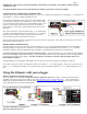
For standalone mode (not connected to an eLogger), connect the
Standalone Cable to the gold pins of the Altimeter, as shown in Figure 1.
Note that the RED wire of the standalone cable corresponds with the red
dot on the label.
The JR/Universal servo end of the Standalone Cable connects to a spare
Receiver channel or small battery. Note that the voltage must be between
3V and 16V. Do not exceed 16V!