
User Manual

Copyright © 2006-2007 Eagle Tree Systems, LLC
http://www.eagletreesystems.com
Instruction Manual for the Brushless Motor RPM Sensor
Document Version 1.7
Thank you for your purchase! This instruction manual will guide you through the installation and operation of your Brushless Motor RPM Sensor (the Sensor).
Please read the entire manual carefully before proceeding. If, after you read the manual, you have further questions or problems, see the Support page on
http://www.eagletreesystems.com for additional information, or email us at support@eagletreesystems.com.
IMPORTANT: It is unlikely that the installation of the Sensor will affect your model’s radio range or control. But, as always after making an electronics
change to your model, it is very important that you range and function test your model once the Sensor is installed to ensure that there is no impact on your
system. Make sure that your “antenna down” operating range is within the manufacturer’s specifications. See your Radio owner’s manual for the correct
procedure for your equipment. DO NOT OPERATE IF YOUR MODEL DOESN’T PASS THE ANTENNA DOWN RANGE CHECK.
Packing List
Your package should include the following: The Brushless Motor RPM Sensor, and a printed version of this manual. Please check your packaging for
printed addenda to this manual which may be included if changes were made after printing.
How the Sensor Works
The Brushless Motor Sensor works with your Data Recorder/MicroPower to measure RPM via pulses from any two of the wires leading from your Electronic
Speed Controller (ESC) to your motor. The sensor works with all known brushless motors. If you have a brushed motor, the sensor will not work.
Brushed motor RPM can be measured with our Magnetic or Optical RPM sensors.
Supported Products
The Sensor works with the following Eagle Tree Products: MicroPower (all versions), and all Seagull Flight Systems and Data Recorder V2 products with
firmware version “4.XX”.
Steps to Follow
Installation and use of your Sensor should be quite easy and enjoyable if you follow these few steps:
1. Read through the manual to understand the warnings, determine the installation and setup sequence,
etc.
2. Upgrade the Windows Application and Firmware for your Recorder as described in the “Windows
Application and Firmware Update” section below.
3. Complete the installation as described below.
Windows Application and Firmware Update
To use the Sensor, you must update to Windows Application version 4.37 or higher. To update, download
the latest application from the support page of our website. After downloading and installing the Application, the firmware of your Recorder may need to
be updated. Firmware version 4.64 or greater is required for the Sensor to work correctly. To upgrade your firmware, choose “Tools, Firmware Control”
and click the Update button.
Connecting the Brushless Motor Sensor the Pro, Flight, Car or Boat Data Recorder
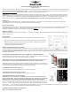
The Sensor plugs into your Data Recorder as shown in Figure 1. Make sure that you connect it in the correct
location on the recorder, and with the correct polarity (the plug is polarized).
NOTE: Make sure the power supply to the Recorder (from the Y cables or separate battery pack) is
less than about 5.6V when using the Brushless RPM Sensor, for the most reliable operation.
The Brushless sensor can also be used as a secondary RPM sensor with your Recorder. Up to 4 RPMs can
be measured in this way (with the Pro Recorder). To use the Brushless sensor as a Secondary sensor, please
see your Seagull or Recorder instruction manual for instructions on modifying it.
Connecting the Sensor to the eLogger V3
The Sensor plugs into the RPM port of the eLogger V3, as shown in Figure 2A.
Connecting the Sensor to the eLogger V1 or V2
The Sensor plugs into the RPM port of the MicroPower, as shown in Figure 2.
Connecting the Sensor to your Power System
WARNING: The wires of the Sensor are designed to carry only the tiny currents required for the
Sensor to measure RPM. The wires must never be connected in a way where large current could flow
through them, or in a way where they could become damaged and short with other conductors.
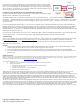
There are two unconnected wires extending from the Sensor, labeled “To Motor 1” and “To Motor 2” (See
Figure 3). These wires need to be electrically connected to any 2 of the 3 wires leading from your ESC to
your motor. The end of these wires can be soldered, clipped or otherwise electrically connected to one of
the motor wires. If you use “bullet” type plugs between your motor and ESC, it is very easy to connect the RPM sensor wires, by just stripping off a short
piece of the insulation, and connecting the bullet plug with the stripped RPM wire inside it.