User Manual for the Seagull Wireless Dashboard Telemetry and Data Recorder Systems Pro, Flight, Glide, Boat Patent Pending Document Version 3.9 Please read this manual before using your new system. Thank you for your purchase! This instruction manual will guide you through the installation and operation of your Pro, Glide, Flight, or Boat Seagull Wireless Dashboard Telemetry or Data Recorder System (the System).
Page 2 Glide System Packing List • Wireless Telemetry Dashboard Receiver and transmitter • Glide Data Recorder • Battery Harness • USB cable, • plastic clip for mounting dashboard to radio antenna, • Windows CD, • Optional: Rubber Antenna with SMA connector for SMA Dashboard option Please see our website support page for updates to this manual if changes were made after printing. Also, check our support page for updates to the Windows software.
Page 3 • It is very important that you “Antenna Down” range check your vehicle per your radio manufacturer’s instructions after installing or reconfiguring any electronic equipment, and generally before each operation. In the unlikely event that you have range issues, see the Troubleshooting section. • The System is to be used only as described in the “Intended Uses” section below. Other uses are not supported, and uses where loss of life or injury may result are expressly forbidden.
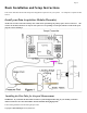
Page 4 Basic Installation and Setup Instructions This section describes the minimal setup and configuration required to use your system. No computer is required for this section. Install your Data Acquisition Module (Recorder) NOTE: The recorder’s label has a handy color coded means of indicating the polarity of the various connectors. The red dots on the label, which are on only one side of the text corresponding to each input, indicate on which side of the plug the red wire should go.
Page 5 Flight Pitot Tube Installations 1. The pickup end of the pitot tube (the silver colored tip) should be pointing toward the direction of the model’s travel. While best results will be obtained if the pitot tube is perfectly aligned with the direction of travel in both axes, the “Prandtl” design of the tube will compensate somewhat for higher angles of attack. 2.
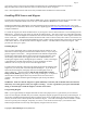
Page 6 type sensors, and up to four using our Exhaust Gas Temperature or Cylinder Head Temperature expanders). Plug the Futaba style connector from the sensor into the recorder as shown in Figure 1. Note: the Temperature Sensor lead can be easily extended with a standard servo extension cable. Installing RPM Sensors and Magnets The following instructions apply to the magnetic RPM sensor, which is included with all systems except the Glide.
Page 7 We are often asked whether existing magnets on spark ignition engines can be used. The answer is “yes” in most cases, if you can install the sensor near enough to rotating magnets. We have found that these engines typically have 3 magnets, with 2 magnets mounted with one polarity, and the other one with another polarity.
Page 8 NOTE: When using secondary RPM sensors in any of the servo ports, servo port monitoring will not work correctly. It is a good idea to select “Do not calibrate servos” in the New Model Wizard if you plan on using multiple RPMs. NOTE: for the secondary RPM sensor to work, there has to be voltage from 4.5 to 6.5 V supplied to one or both of the servo inputs (as shown in Figure 1). This is normally done with the Y Cables, a separate battery, or your BEC.
Page 9 NOTE: Customers without the Seagull System should now proceed to the section entitled “Advanced Installation and Setup Instructions” Choose a location in your vehicle to install the transmitter. The transmitter is normally mounted with Velcro or double sided tape. Ideally, the transmitter will be installed with its antenna and body as far away from your radio receiver (RX) as possible, with the antenna protruding at right angles with your RX antenna, to reduce the possibility of interference.
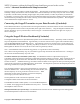
Page 10 USB Connection: The USB cable supplied with your Recorder connects to the Dashboard at this port. Note that the RED wire of the USB cable goes up, as shown by the red dot above “USB” on the Dashboard label. NOTE: If you have a 9V battery in the Dashboard, the Dashboard must be powered on before connecting to USB. LCD Display: The 16 x 2 LCD character display is easily programmed to display up to four vehicle parameters per screen page.
Page 11 • • • • “Vario Climbrate” – this setting controls the minimum climbrate. When you ascend at a rate greater than this climbrate, the variometer will start to sound, as described in the “Variometer” section above. Pressing up/down arrows changes this parameter. “Vario Freq Shift” – This setting changes the amount the pitch changes as the climbrate increases/decreases. If you are not hearing enough change, increase this parameter, and vice versa for too much frequency change.
Page 12 Advanced Installation and Setup Instructions This section describes more advanced setup and configuration. A computer is required for this section, and some features listed require optional accessories. Connecting the Recorder to Your Models Servos and Receiver With the four included (optional with Glide Systems) Servo ‘Y’ cables, you will be able to monitor your model’s servo movements (up to four channels, or two channels with the Boat System).
Page 13 The supplied Windows application is compatible with USB equipped PCs running Windows 98SE, Millennium, Win 2K, and Win XP. The application is not compatible with Windows 98 Original Edition (Gold), or NT 4, even if the PC has USB support. NOTE: the application included on CD with the unit was current at the time of manufacture. Please check our Support page on http://eagletreesystems.com to see if there is a newer version of the software which may have addressed issues you could encounter.
Page 14 Servo movements: If one or more of these parameters is checked, the recorder will log the positions of the corresponding servos, assuming you have the optional ‘Y’ cables installed. Choose these options if you want to see controller movements during your flight, etc. . Servo Glitches (requires Y cable installation): If this option is selected, the recorder detects and logs three different types of servo glitches: short servo pulses (less than 740uSec), long servo pulses (greater than 2.
Page 15 Altitude: If this option is selected, the recorder logs the model’s altitude with each sample. RPM: If this option is selected, the recorder logs the RPM of your session. Temperature 1: Choose this option if you want to record temperature from the temperature sensor plugged into the “Tmp1” slot, sold separately. Temperature 2: Choose this option if you want to record temperature from the temperature sensor plugged into the “Tmp2” slot, sold separately.
Page 16 Setting the “Choose What to Display” Feature The software can display several data parameters in both numeric and instrument format. The software displays these parameters both for data downloaded from the recorder, and in “Live Mode” from the Seagull Dashboard. Select the parameters you wish the Application to display on the PC screen by clicking “Software, Choose Instruments to Display on the PC Screen.
Page 17 rotation of the magnets as described in this dialog box. If you have an optical or brushless RPM sensor, please see the instructions included with that sensor. Note: You can change this setting later from the “Calibrate” software menu. Setting Metric or English Units Metric or English units are selected via the Windows Recorder Application (the App). The default setting is English units. To change this, Click “Tools, Choose What to Display” in the software, and click on “Display In Metric.
Page 18 Seagull Dashboard Data Setup Utility Instructions This utility (the Utility) will appear the first time you run the software, and can be re-run by selecting “Hardware, Choose Parameters to Display on the Wireless Dashboard LCD” in the Software. This utility is the tool used to configure Seagull Dashboard – it gives you the capability of configuring all of the items displayed on the LCD screen, setting up alarms, etc. You need to connect the Dashboard to USB before running the utility.
Page 19 The window labeled “Enter the label to display..” in this section displays the 3 digit label that will be displayed beside this parameter on the LCD. You can change this 3 digit label to be whatever you want. For example, if Temperature Sensor 1 was attached to your Cylinder Head, you might label this parameter “CHT.” NOTE: If the data for each parameter grows large, such as a large RPM, the middle character in the 3 digit label will be eliminated to show all the numeric digits in the parameter.
Page 20 Configuring Variometer Alarms (Pro and Glide Systems only) If you wish to configure climbrate and/or sinkrate alarms for variometer support, click the Climbrate/Variometer button in the alarms section. Note that the Variometer/Climbrate button will only appear when the Variometer parameter is selected and Enabled. Note also that when the Variometer parameter is enabled, the Configure Variometer page will also automatically appear. Carefully read the instructions on the Configure Variometer page.
Page 21 Using your Seagull in Laptop Live Mode If you have a laptop at your site, or wish to see live data with your vehicle on the bench, the software can be used to view the Seagull data parameters live in a “big screen” format, with almost infinite recording capability! To use Live Mode, first select “Tools, Choose What to Display” in the software, and set up the parameters you want to display.
Page 22 Two Flashes – The recorder is paused. This has happened either because the Recorder’s data buffer is full and you have selected the “stop on full” mode described above, or you have manually paused the Recorder as described below in the Recorder Button section. Three Flashes – The Recorder is connected to your PC’s USB connector, and has been recognized by the PC. The Recorder’s Pushbutton The small red pushbutton on the Recorder serves two purposes.
Page 23 Other display options are available with optional equipment from Eagle Tree Systems. Multiple Session Support Depending on the length of your modeling sessions, it is often possible to record multiple runs into the Recorder without having to clear the buffer or overwrite data. The Recorder application will split multiple sessions automatically for you.
Page 24 Code 3, EVENT_INITIALIZE_FAILED - internal, Code 4, EVENT_CANT_SEND_HEADER - internal, Code 5, EVENT_CANT_SEND_ANALOG_PACKET - internal, Code 6, EVENT_CANT_SEND_DATA_PACKET - internal, Code 7, EVENT_BATTERY_LOW – battery has fallen below a safe level for an extended period of time, Code 8, EVENT_BATTERY_DEAD – not used Code 9, EVENT_RESTART – the recorder has been restarted normally, Code 10, EVENT_NESTED_INT_DISABLE - internal, Code 11, EVENT_ILLEGAL_INT - internal, Code 12, EVENT_LOW_BAT_RESTART
Page 25 Solution: Slight drift right after system power-up is normal. Turning the Dashboard off and on about a minute after power-up should remove most drift from the display. Solution: Some slight drift may occur if large changes in temperature are occufing. Note that for airspeed, which is related to the square of pressure, slight drift from zero will not affect your higher speed readings much.
Page 26 Issue: I have a fully charged battery, but the recorder frequently shows “Low Battery Restart” Notifications when playing back data. Solution: The recorder shuts down immediately if the power goes below about 4.5 volts for more than a few milliseconds, and logs this occurrence when the power returns to above 4.5 volts. If your battery’s voltage frequently drops this low, you may be underpowered, and may want to consider getting a bigger battery.
Page 27 Tested to Comply With FCC Standards FOR HOME OR OFFICE USE FCC Radiation Exposure Statement Regarding the FCC Certified 900 MHz and 2.4 GHz Transmitters This equipment complies with FCC radiation exposure limits set forth for an uncontrolled environment. This equipment must be operated with minimum distance of 20cm between the radiator and your body. The Transmitter must not be co-located or operating in conjunction with any other antenna or transmitter.
Page 28 Pitot Tube Weight 3 grams (0.1 oz), length 80mm (3.2”), diameter 4 mm (0.16”) FCC 900 MHz, 200mW Transmitter Operational Voltage: Frequency Range: Operating Range (Line of Sight): FCC Approval: Maximum Output Power: Dimensions: Weight: Temperature Range: TX Antenna: Power: Current Draw: 4.35V to 7.0V 902 – 928 MHz up to 1.2 miles w/included antenna, up to 3.6 miles with RX Yagi 15.247 Frequency Hopping Spread Spectrum approx 200 mWatt approx 2-3/4” x 1-1/4” x ¼” approx 0.
Page 29 Current Draw: Transmitter + Recorder, average < 60 milliamp Receiver RX Antenna: Temperature range: Battery: Display: Pushbuttons: USB connection: Thin, flexible stainless whip 0 – 140 degrees F Standard 9V (or other 5V to 16V battery pack) 16x2 character LCD 4 Yes Limited Warranty Eagle Tree Systems, LLC, warrants System to be free from defects in materials and workmanship for a period of one (1) year from the date of original purchase. This warranty is nontransferable.
Page 30 Registering your product means that we can send you important updates and other notifications. Please fill out this form (or a copy) and mail or fax it to Eagle Tree Systems. Or, email the info to sales@eagletreesystems.com. Note that if you purchased your item directly from Eagle Tree Systems, this is not necessary.