
Instructions for use

Copyright © 2007 Eagle Tree Systems, LLC
http://www.eagletreesystems.com
Instruction Manual for Servo Current Monitor MicroSensor
Document Version 1.2
Thank you for your purchase! This instruction manual will guide you through the installation and operation of your Servo Current MicroSensor (the
Sensor). Please read the entire manual carefully before proceeding. If, after you read the manual, you have further questions or problems, see the
Support page on http://www.eagletreesystems.com for additional information, or email us at support@eagletreesystems.com.
IMPORTANT: It is extremely unlikely that the installation of the Sensor will affect your model’s radio range or control. But, as always after making an
electronics change to your model, it is very important that you range and function test your model once the Sensor is installed to ensure that there is no
impact on your system. Make sure that your “antenna down” operating range is within the manufacturer’s specifications. See your Radio owner’s manual
for the correct procedure for your equipment. DO NOT OPERATE IF YOUR MODEL DOESN’T PASS THE ANTENNA DOWN RANGE
CHECK.
Packing List
Your package should include the following: The Sensor with universal servo connectors, and a printed version of this manual. Please check our support
web page for the electronic version of this manual which may be updated if changes were made after printing.
What the Sensor Does
The Sensor is a precision Ammeter, with 0.01A resolution. It is capable of recording up to +/-10A burst current, but no more than +/-5A continuous current.
It connects to your MicroPower eLogger, Seagull, or Data Recorder product to provide current/amperage measurement of Servos, or other low amperage
devices. Servo Current can be displayed and analyzed in 3 ways: 1) The live current and maximum current are displayed on the PowerPanel LCD or
Seagull Dashboard Display. This is very useful for quickly seeing how much current your servo(s) are drawing without using a PC. 2) Servo Current is
logged in the Recorder, for download to your PC. 3) Servo Current is displayed and graphed (charted) with the Eagle Tree Windows application, or a
spreadsheet program.
Supported Products
The Sensor works with all versions of the MicroPower eLogger product, with all versions of our “Pro” and “Glide” systems, and with flash upgradeable
firmware versions of our Seagull Flight, Car and Boat (and Recorder) products (units with firmware version “4.xx”). If you have a “3.xx” or lower recorder
firmware version, a hardware upgrade is required. Please see our support web page for more information on hardware upgrades.
Steps to Follow
Installation and use of your Sensor should be quite easy and enjoyable if you follow these few steps:
1. Read through the manual to understand the warnings, determine the installation and setup sequence, etc.
2. Upgrade the Windows Application and Firmware for your Recorder as described in the “Windows
Application and Firmware Update” section below.
3. Install and configure the Sensor as described below.
Windows Application and Firmware Update
To use the Sensor, you must update to Eagle Tree Windows Application version 5.50 or higher. To update,
download the latest application from the support page of our website, located at
http://eagletreesystems.com/Support/apps.htm . After downloading and installing the Application, the
firmware of your MicroPower eLogger or Recorder and Dashboard will need to be updated. Version 4.91 or
greater eLogger/Recorder firmware is required for the Sensor to work correctly. Version 4.50 or greater Seagull Dashboard firmware is required if
you are using the Sensor with the Wireless Dashboard. To upgrade your firmware, just choose “Tools, Firmware Control” and click the Update button.
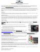
Connecting the MicroSensor to the eLogger V3
The MicroSensor plugs into the “LCD/TX” port of your eLogger V3, as shown in Figure 1A. If you have a
PowerPanel or other MicroSensors, those can “daisy chain” connect to the pins on the other side of your
MicroSensor, with the polarity as indicated on the MicroSensor label.
Connecting the Sensor to the eLogger V1/V2
The Sensor plugs into the “Aux” or “LCD” port of your MicroPower eLogger V1/V2, as shown in Figure 1.
If you have a PowerPanel or other MicroSensors, those can “daisy chain” connect to the pins on the other
side of your Sensor, with the polarity as indicated on the Sensor label.
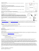
Connecting the Sensor to the Data Recorder
The 4 wire connector attached to the Sensor plugs into either the G-Force or EGT (“Thermo”) port of your
Data Recorder as shown in Figure 2. Make sure that you connect it in the correct location on the recorder, and with the correct polarity! NOTE: The
Servo Current Sensor is connected with the red wire on the left, which is backwards from the normal G-Force, EGT and transmitter connections.
Also, if you are already using both EGT and G-Force expanders, one of those can “daisy chain” to the Sensor as described in the MicroPower section above.
Configuring the Sensor with the Windows Application
If you have not already done so, set up the Recorder software as described in your instruction manual. Then, choose one or more of the Sensor options
below: