Pub. 988-0143-842 www.eaglesonar.
Copyright © 2006 LEI-Eagle All rights reserved. No part of this manual may be copied, reproduced, republished, transmitted or distributed for any purpose, without prior written consent of Eagle Electronics. Any unauthorized commercial distribution of this manual is strictly prohibited. Eagle® is a registered trademark or LEI. Cuda® 242 is a registered trademarks of LEI. Eagle Electronics may find it necessary to change or end our policies, regulations, and special offers at any time.
Table of Contents Introduction.......................................................................................1 Specifications: Cuda 242 & Cuda 242 Portable ...........................1 How Sonar Works.................................................................................3 Preparations .........................................................................................4 Installation ...........................................................................................
® Grayline .............................................................................................43 Chart Speed ........................................................................................45 Fish I.D. ...........................................................................................47 FishTrack™ ........................................................................................48 Alarms........................................................................................
Introduction Thank you for buying an Eagle sonar! Your unit is a high-quality sonar designed for both professional and novice fishermen. All Eagle sonars have an automatic mode that finds and displays the bottom, fish, underwater structure and more – right out of the box. All you have to do is press the on (PWR) key. To get started with your Eagle sonar, first read the installation section.
Current drain: ................170 ma lights off; 240 ma lights on. Back-up memory:...........Built-in memory stores sonar settings when unit is turned off. Sonar Frequency: ......................200 kHz. Transducers:...................A Skimmer transducer comes packed with your unit. Its 20° cone angle offers a wide fish detection area of up to 60º with high sensitivity settings. Operates at boat speeds up to 70 mph (61 kts). Transmitter:....................
This manual covers the Cuda 242 and Cuda 242 Portable. Both units operate the same way. The only difference between the two is that the portable unit includes a portable transducer and other items that enable portable use. NOTICE! The storage temperature for your unit is from -4 degrees to +167 degrees Fahrenheit (-20 degrees to +75 degrees Celsius). Extended storage in temperatures higher or lower than specified will damage the liquid crystal display in your unit.
Transducer Installation Preparations The following shows the recommended sequence for installing the transducer: CAUTION: You should read over this entire installation section before drilling any holes in your vehicle or vessel! 1. Determine the approximate location for the sonar unit, so you can plan how and where to route the cables for the transducer and power. This will help you make sure you have enough cable length for the desired configuration. 2.
These are all "kick-up" mounting brackets. They help prevent damage if the transducer strikes an object while the boat is moving. If the transducer does "kick-up," the bracket can easily be pushed back into place without tools. Depending on your sonar unit's connectors, your transducer cable may also have the sonar unit's power cable attached to it. If that is the case, be sure to install the transducer first, before connecting the power cable to a power source.
mulated epoxy adhesive available from LEI (see ordering information on the inside back cover). A sandwich hull also requires polyester resin. Selecting a Transducer Location 1. The location must be in the water at all times, at all operating speeds. 2. The transducer must be placed in a location that has a smooth flow of water at all times.
5. If possible, route the transducer cable away from other wiring on the boat. Electrical noise from engine wiring, bilge pumps and aerators can be displayed on the sonar's screen. Use caution when routing the transducer cable around these wires. CAUTION: Clamp the transducer cable to transom near the transducer. This will help prevent the transducer from entering the boat if it is knocked off at high speed.
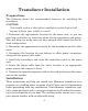
Transom Transducer centerline Hull bottom Align transducer centerline with hull bottom. However, there are times when you may need to adjust the transducer slightly higher or lower. (The slots in the mounting brackets allow you to loosen the screws and slide the transducer up or down.) If you frequently lose bottom signal lock while running at high speed, the transducer may be coming out of the water as you cross waves or wakes. Move the transducer a little lower to help prevent this.
There is no possibility of damage from floating objects. It can't be knocked off when docking or loading on the trailer. However, the shoot-thru-hull installation does have its drawbacks. First, some loss of sensitivity does occur, even on the best hulls. This varies from hull to hull, even from different installations on the same hull. This is caused by differences in hull lay-up and construction. Second, the transducer angle cannot be adjusted for the best fish arches.
Dot Align plastic ratchets in bracket. 2. Aligning the transducer on the transom. Slide the transducer between the two ratchets. Temporarily slide the bolt though the transducer assembly and hold it against the transom. Looking at the transducer from the side, check to see if it will adjust so that its face is parallel to the ground. If it does, then the "A" position is correct for your hull. If the transducer's face isn't parallel with the ground, remove the transducer and ratchets from the bracket.
Ratchets Insert bolt and check transducer position on transom. 3. Assembling the transducer. Once you determine the correct position for the ratchets, assemble the transducer as shown in the following figure. Don't tighten the lock nut at this time. Nut Metal washer Rubber washers Metal washer Bolt Assemble transducer and bracket. 4. Drilling mounting holes. Hold the transducer and bracket assembly against the transom.
the ground. The transducer's centerline should be in line with the bottom of the hull. Don't let the bracket extend below the hull! Mark the center of each slot for the mounting screw pilot holes. You will drill one hole in the center of each slot. Drill the holes. Use the #29 bit (for the #10 screws). Transom Transom Position transducer mount on transom and mark mounting holes. Side view shown at left and seen from above at right. 5. Attaching transducer to transom.
Route cable over bolt and through bracket. Side view shown (left) and seen from above (right). Attach the transducer to the transom. Slide the transducer up or down until it's aligned properly with the bottom of the hull as shown in the preceding and following figures. Tighten the bracket's mounting screws, sealing them with the caulking compound. Adjust the transducer so that it's parallel to the ground and tighten the nut until it touches the outer washer, then add 1/4 turn.
Bottom of hull Deep-"vee" hull Flat-bottom hull Align transducer centerline with hull bottom and attach to transom. 6. Route the transducer cable through or over the transom to the sonar unit. Make sure you leave some slack in the cable at the transducer. If possible, route the transducer cable away from other wiring. Electrical noise from the engine's wiring, bilge pumps, VHF radio wires, cables and aerators can be picked up by the sonar. Use caution when routing the transducer cable around these wires.
7. Make a test run to determine the results. If the bottom is lost at high speed, or if noise appears on the display, try sliding the transducer bracket down. This puts the transducer deeper into the water, hopefully below the turbulence causing the noise. Don't allow the transducer bracket to go below the bottom of the hull! Trolling Motor Bracket Installation 1. Attach the optional TMB-S bracket to the transducer as shown in the following figure, using the hardware supplied with the transducer.
3. Route the transducer cable alongside the trolling motor shaft. Use plastic ties (not included) to attach the transducer cable to the trolling motor shaft. Make sure there is enough slack in the cable for the motor to turn freely. Route the cable to the sonar unit and the transducer is ready for use. Transducer mounted on trolling motor, side view.
Partial fish arches Transducer aimed too far forward Transducer aimed too far back Full fish arch Proper transducer angle Transducer angles and their effects on fish arches. If the arch slopes up – but not back down – then the front of the transducer is too high and needs to be lowered. If only the back half of the arch is printed, then the nose of the transducer is angled too far down and needs to be raised. NOTE: Periodically wash the transducer's face with soap and water to remove any oil film.
Shoot-Thru-Hull Preparation Hulls with Flotation Materials The transducer installation inside a fiberglass hull must be in an area that does not have air bubbles in the resin or separated fiberglass layers. The sonar signal must pass through solid fiberglass. A successful transducer installation can be made on hulls with flotation materials (such as plywood, balsa wood or foam) between layers of fiberglass if the material is removed from the chosen area. See the figure below.
sonar signal must pass through solid fiberglass. Any air bubbles in the fiberglass or the epoxy will reduce or eliminate the sonar signals. Testing Determines Best Location Ideally, the shoot-thru transducer should be installed as close to the transom as possible, close to the centerline. This will give you the best performance during high speed maneuvers. Transducer location (high speed) Transducer location (trolling speed) Shoot-thru-hull transducer locations for high speed or trolling speed operation.
True bottom Second bottom Manual range setting Example of a second bottom signal. Unit is in 30 feet of water, with range set at 80 feet and sensitivity set at 87 percent. 2. Next, take the transducer out of the water and place it in the water in the sump of the boat, face down. (The transducer face is shown in the figure on the following page.) Notice how the signal strength decreases. The second bottom signal will probably disappear and the bottom signal intensity will likely decrease. 3.
4. Most people can get good results by following steps 1 through 3, so this step is optional. If you want to make an extra effort to be absolutely sure that your selected location will work under all conditions, make a test run with the boat on plane and observe the bottom signal. You'll need to figure some way to prop the transducer into position while you make your test run. (A brick or two might be sufficient to hold it in place.) 5.
Spread epoxy here Sand this surface Orient the Skimmer with the nose facing the bow of the boat. To bow Epoxy transducer to hull. WARNING: Use only the epoxy available from LEI. It has been formulated to work with these installation procedures. Other epoxy types may be too thin or may not cure to the right consistency for optimum transducer performance. 2. The epoxy consists of the epoxy itself and a hardener. Remove the two compounds from the package and place them on the paper plate.
Make sure there are no air pockets in the epoxy layer! Then, apply the remaining epoxy to the sanded area on the hull. 3. Press the transducer into the epoxy, twisting and turning it to force any air bubbles out from under the transducer face. Stop pressing when you bottom out on the hull. When you're finished, the face of the transducer should be parallel with the hull, with a minimum amount of epoxy between the hull and transducer. 4.
stalling an inline switch. This will let you shut off power to the power cable when the unit is not in use. When you are not using the unit, you should always shut off power to the power cable, especially when the power cable is disconnected from the unit. Red wire with 3 amp fuse To unit Black wire 12 volt battery Power connections for the Cuda 242 sonar unit (direct battery connection shown). If possible, keep the power cable away from other boat wiring, especially the engine's wires.
This unit has reverse polarity protection. No damage will occur if the power wires are reversed. However, the unit will not work until the wires are attached correctly. Mounting the Sonar Unit: In-Dash, Bracket or Portable You can install the sonar unit on the top of a dash with the supplied bracket. This unit can be installed in a dash with the optional FM-6 indash adapter kit. The FM-6 kit includes an instruction sheet, part 9880147-631, which contains a template for cutting out the mounting hole.
82.7 [3.26] 107.5 [4.23] 156 [6.26] 12.09 [0.48] 76.9 [3.03] Millimeter [Inch] 70.3 [2.77] Front view (left) and side view (right) showing dimensions of the Cuda 242 when mounted on quick release bracket. After drilling the hole, pass the connectors up through the hole from under the dash. If you wish, you can fill in the hole around the cable with a good marine caulking compound. (Some marine dealers stock cable hole covers to conceal the opening.
Align the bracket over the cable hole with the cable slots facing away from you and fit the cable through one of the slots. Fasten the bracket to the dash using the three screw holes. Ratchet Rear (away from viewer) Screw hole Power/transducer cable Cable slot Cuda 242 quick release mounting bracket. Slots in the base allow routing the cable from beneath the mount. Attach the unit to the bracket by first connecting the power/transducer and accessory cables.
Bracket front Mount the sonar: slide the unit onto the bracket from above. Depress ratchets to release Adjust viewing angle: use one hand to press and release the springloaded ratchets while you move the unit with the other hand. Portable Sonar Installation Like many Eagle products, the Cuda 242 sonar is capable of portable operation. It uses the optional PPP-12 portable power pack.
The power pack and portable transducers expand the uses for your sonar. You can use your Cuda 242 sonar unit on your boat or take it to the dock, on a float tube, on an ice fishing trip or use it as a second sonar in a friend's boat. The PPP-12 package includes the power pack, battery adapter and a portable transducer. The transducer can be stored inside the power pack. The PPP-12 requires eight AA alkaline batteries. Batteries are not included.
mount. Close the case bottom, using the slot in the case wall to avoid pinching the cable. Turn the unit over to mount the sonar. CAUTION: When using the sonar in a saltwater environment, we strongly recommend that you unplug the power connector from the battery socket when the unit is not in use. When the unit is turned off but still connected to a power supply, electrolysis can occur in the power cable plug.
To adjust the viewing angle, pinch the quick-release mount's ratchets with one hand, then tilt the unit with your other hand. Release the ratchets and the unit locks into the new position. To remove the unit from the PPP-12, press the ratchets and lift the unit off the bracket. Turn the sonar unit on. If it works, turn it off and finish assembling the portable transducer. If it doesn't work, make sure the battery terminals are making good contact against the battery contacts.
Tie nylon cord here Suction cup Bolt Washer Screw Nut Washer Transducer Portable transducer assembly: rear view (left) and side view (right). Clean the chosen area of the hull before attaching the suction cup. Locate the transducer on the hull as shown in the following figure. Don't let the bracket extend below the hull, because water pressure against it can cause the suction cup to come off at speed.
Hull Portable transducer installed on boat transom. Portable Transducer Storage There is room inside the power pack for the portable transducer. When you're finished fishing, tilt the sonar down to the storage position. Open the case and lay it flat. Unplug the power connector from the battery compartment socket. Wrap the transducer cable around the suction cup, then stow the transducer on top of the battery compartment cover. Close the case and your equipment is ready for transport.
Notes 34
Operation Keyboard Basics The unit sounds a tone when you press any key. This tells you the unit has accepted a command. Numbers in the figure correspond to key explanations below: 1 3 2 Eagle Cuda 242 keyboard. 1. PWR/CLEAR In this manual, the Power/Clear key is referred to as PWR. Press this key to turn the unit on and off. It also clears menus and menu selections from the screen. To clear a menu from the screen, press PWR. NOTE: Hold the PWR key down for five seconds to turn off the unit.
2. MENU UP & MENU DOWN These keys appear in the manual text as MENU UP or MENU DOWN. Most of the time, you can press either of the menu keys, so in those cases, the text uses the word MENU. Usually, when the instructions say MENU, you can press the MENU UP key for consistency. The MENU UP key cycles forward through the menus. The MENU DOWN key moves backward through the menus. To check out the menus, repeatedly press a MENU key to scroll through them. 3.
The Backlight menu with backlight turned on. Display The lights will flash for about 10 seconds when the unit is turned on. The backlight menu will appear on the screen. Use the ARROW keys to turn the backlight on or off. Press PWR to clear the menu from the screen. The unit will show the Full Chart Page or mode. The Fish I.D. fish symbol feature is on. The depth range is displayed as the upper and lower limit on the left side of the screen.
Digital depth Surface signal Water Temp Fish symbols Bottom signal Structure or cover Depth range at bottom of depth scale Grayline Opening screen, Full Chart page, or mode. The factory default setting has the Fish I.D. (fish symbols) turned on. Full Chart The unit's default page, Full Chart shows all echoes scrolling across the full screen. The bottom signal scrolls across the screen from right to left. The line at the top of the screen represents the surface.
If the transducer with a built-in temperature sensor is connected, a digital display for water temperature also will be shown. This temperature display can be turned on and off. Depth Range When turned on, the unit automatically adjusts the depth range according to water conditions. When in auto range mode, it always keeps the bottom displayed in the lower portion of the screen. You can override the automatic depth range control and manually select a depth range.
Zoom The zoom feature enlarges all images on the screen by doubling the size of the echoes (a 2X zoom). For example, if the current auto depth range is 0 to 60 feet, Zoom will show an enlarged view of the water column from 30 feet to 60 feet, always keeping the bottom in view. To zoom the display, press the MENU key until the ZOOM menu appears. Press ↑ to select ON, then press PWR to clear the menu. Zoom feature turned off (left). Zoom turned on (right).
NOTE: Using the Zoom command while in auto Zoom mode will always enlarge the echoes near the bottom, because auto Range always keeps the bottom displayed in the lower portion of the screen. When you choose to use the zoom feature while the unit is in manual Depth Range mode, you can select one of 17 pre-set Zoom Ranges. This lets you enlarge a desired segment of the water column. To do this, make sure Depth Range is set to manual mode. Next, press MENU until the ZOOM menu appears.
Sensitivity Sensitivity adjusts the way echoes will be displayed on the screen. If you want to see more detail, try increasing the sensitivity, a little at a time. There are situations when too much clutter appears on the screen. Decreasing the sensitivity can reduce the clutter and show the strongest fish echoes, if fish are present. As you change the sensitivity setting, you can see the difference on the chart as it scrolls. Sensitivity set to manual mode (left). Sensitivity control bar (right).
MANUAL, then press PWR to clear the menu. To adjust the sensitivity, follow the same steps used for adjusting sensitivity in auto mode above. Bait school Fig. 2 Fig. 1 Fish arches Fig. 3 Fig. 4 These figures show results of different sensitivity levels on the same location. Fig. 1: Sensitivity at 98 percent, determined by Auto Sensitivity. Typical of full auto mode. Fig. 2: Sensitivity set at 71 percent. Fig. 3: Sensitivity set at 47 percent. Fig. 4: Sensitivity set at 100 percent.
ample, a soft, muddy or weedy bottom returns a weaker signal which is shown with a narrow line or no gray line at all. A hard bottom returns a strong signal which will be displayed as a wide gray line. Grayline control bar. If you have two signals of equal size, one with gray and the other without, then the target with gray is the stronger signal. This helps distinguish weeds from trees on the bottom, or fish from structure. Grayline is adjustable.
Wider Grayline Thin or no Grayline A small amount of Grayline indicates a soft bottom (left), probably sand or mud. More Grayline indicates a harder, rocky bottom (right). Press ↑ to increase the level of Grayline or press ↓ to decrease it. Echoes scrolling onto the screen will show the effects of the Grayline change. If you reach the maximum or minimum level, a tone sounds alerting you to the limits. Press PWR to clear the menu.
Chart Speed control bar. You, however, might consider experimenting with chart speed when you are stationary or drifting very slowly. Sometimes, you may achieve better images as you decrease the chart speed to match the speed of your boat. If you are at anchor, ice fishing or fishing from a dock, experiment with a chart speed of 25 percent. If you are drifting slowly, try a chart speed of 50 percent.
Fish I.D. The Fish I.D. feature displays — as fish— targets that meet certain conditions. The microcomputer analyses all echoes and eliminates surface clutter, thermoclines and other undesirable signals. The Fish I.D. feature displays symbols on the screen in place of the actual fish echoes. There are three symbol sizes: small, medium and large. These show the relative size between targets.
You may see Fish I.D. symbols on the screen when actually, there are no fish. The reverse is also true — Fish I.D. can actually miss fish that are present. Does that mean Fish I.D. is broken? No — the feature is interpreting sonar returns in a specific way to help take some of the work out of reading the screen. Remember: Fish I.D. is one of the many tools we provide so you can analyze your sonar returns for maximum fish finding information.
Fish I.D. symbols showing FishTrack depth indicator Fish ID menu and symbol with FishTrack on. The fish is 44 feet deep. Alarms The sonar unit has four types of alarms: fish, shallow, deep and battery. Fish Alarm menu. Fish Alarm The Fish Alarm sounds a tone when a fish symbol appears on the screen. The Fish I.D. feature must be turned on for fish alarms to work.
To turn on Fish I.D., press MENU until the FISH ID menu appears. Press ↓ to select ON, then press PWR. Press MENU until the FISH ALARM menu appears. Press ↑ to select ON, then press PWR. To turn off fish alarm press MENU until FISH ALARM appears. Press ↑ to select OFF, then press PWR to clear the menu. Depth Alarms The depth alarms are triggered only by the bottom signal. No other echoes will activate these alarms. The depth alarms consist of a shallow and a deep alarm.
depth has been entered in the dialog box. To move the cursor back to any of the previously entered numbers, press UP MENU. Otherwise, press PWR to return to the Shallow Alarm menu. Use ↑ to select ON, which will turn on the alarm, then press PWR to clear the menu. When the bottom depth becomes shallower than the alarm’s setting, an alarm will sound and a message will appear on the screen. Press PWR to silence the alarm. It will remain silent until it is triggered again.
press PWR to return to the Deep Alarm menu. Use ↑ to select ON, which will turn on the alarm, then press PWR to clear the menu. When the bottom depth becomes deeper than the alarm’s setting, an alarm will sound and a message will appear on the screen. Battery Alarm To set the shallow alarm depth, press MENU repeatedly until BATTERY ALARM appears. Low Battery Alarm Value (left). Battery Alarm menu (right). Press the ↓ to SET VALUE. The Low Battery Alarm Value dialog box will appear.
Noise Reject and ASP The ASP (Advanced Signal Processing) feature is a noise rejection system built into the sonar unit. It constantly evaluates the effects of boat speed, water conditions and electrical interference and automatically gives you the best display possible under most conditions. ASP is an effective tool in combating noise. In sonar terms, noise is any undesired signal.
There are times when you may want to turn off ASP. This allows you to view all incoming echoes before they are processed by the ASP feature. To change the ASP setting, press MENU DOWN until the NOISE REJECTION menu appears. Use ↑ ↓ to select the desired setting, then press PWR to clear the menu. Depth Display Depth may be displayed on the screen in a small, medium or large size or can be turned off completely. To display Depth: Repeatedly press MENU until the DEPTH menu appears.
Temperature menu set to off (left). Temperature set to be displayed at small size (right). To display Temperature: Repeatedly press MENU until the TEMPERATURE menu appears. Use ↑ ↓ to select the size of the temperature display. Press PWR to clear the menu. Voltage menu with the voltage display turned off (left) and with voltage set to a small display size (right).
Voltage The Voltage menu allows you to display battery voltage on the screen in a small or medium size or can be turned off completely. To display battery voltage: Repeatedly press MENU until the VOLTAGE menu appears. Use ↑ ↓ to select the size of the voltage display. Press PWR to clear the menu. Units This unit can show the depth in feet or meters and temperature in Celsius or Fahrenheit. When the units are changed to feet, the temperature will be listed as Fahrenheit.
Backlight The display's backlight allows the unit to be used at night. To turn the backlight on or off, press MENU repeatedly until the BACKLIGHT menu appears. Press ↑ to turn the light on or ↓ to turn it off. Backlight turned on (left). Contrast control bar (right). Contrast The unit’s display contrast is adjustable to suit different lighting conditions. It will help you see the screen from different angles or at various times of the day..
Simulator Simulator menu. This unit has a built-in simulator that shows a simulated bottom signal with fish signals. This lets you practice with the unit as if you were on the water; all features and functions of the unit are usable. A message appears occasionally to remind you that the simulator is on. To use the simulator, repeatedly press MENU until the SIMULATOR menu appears. Press ↑ to turn it on and press PWR to clear the menu.
Language menu with English selected (left) and Italian (right). To select a language: 1. Repeatedly press MENU until the Languages menu appears. 2. Use ↑ ↓ to select the desired language. All menus now appear in the language you selected. Press PWR to exit. Software Information To show the operating software system information, press MENU until the SOFTWARE INFORMATION menu appears. Press PWR to clear the screen.
Software information screen. Reset Options This command is used to reset all features, options and settings to their original factory defaults. This is useful when you have changed several settings and want to reset the unit to basic automatic operation. Turn the unit off. Press and hold ↓ and the MENU DOWN key at the same time while you press the PWR key. Release the keys as the unit powers up. The unit will turn on with factory settings restored.
Troubleshooting If your unit is not working, or if you need technical help, please use the following troubleshooting section before contacting the factory customer service department. It may save you the trouble of returning your unit for repair. For contact information, refer to the last page, just inside the back cover of this manual. Unit won't turn on: 1. Check the power cable's connection at the unit. Also check the wiring. 2. Make certain the power cable is wired properly.
Weak bottom echo, digital readings erratic, or no fish signals: 1. Make certain the transducer is pointing straight down. Clean the face of the transducer. Oil, dirt and fuel can cause a film to form on the transducer, reducing its effectiveness. If the transducer is mounted inside the hull, be sure it is shooting through only one layer of fiberglass and that it is securely bonded to the hull. Do NOT use RTV silicone rubber adhesive or Marine-Tex epoxy. 2.
Try using resistor spark plugs or routing the sonar unit's power and transducer cables away from other electrical wiring on the boat. No fish arches when the Fish I.D. feature is off: 1. Make certain the transducer is pointing straight down. This is the most common problem if a partial arch is displayed. 2. The sensitivity may not be high enough. In order for the unit to display a fish arch, it has to be able to receive the fish's echo from the time it enters the cone until it leaves.
and transmit. Keep doing this until all electrical equipment has been turned on, their effect on the sonar display noted, then turned off. If you find noise interference from an electrical instrument, trolling motor, pump, or radio, try to isolate the problem. You can usually reroute the sonar unit's power cable and transducer cable away from the wiring that is causing the interference. VHF radio antenna cables radiate noise when transmitting, so be certain to keep the sonar's wires away from it.
EAGLE ELECTRONICS FULL ONE-YEAR WARRANTY "We," "our," or "us" refers to EAGLE ELECTRONICS, a division of LEI, the manufacturer of this product. "You" or "your" refers to the first person who purchases this product as a consumer item for personal, family, or household use. We warrant this product against defects or malfunctions in materials and workmanship, and against failure to conform to this product's written specifications, all for one (1) year from the date of original purchase by you.
How to Obtain Service… …in the USA: We back your investment in quality products with quick, expert service and genuine Eagle replacement parts. If you're in the United States and you have technical, return or repair questions, please contact the Factory Customer Service Department. Before any product can be returned, you must call customer service to determine if a return is necessary. Many times, customer service can resolve your problem over the phone without sending your product to the factory.
Accessory Ordering Information for all countries To order Eagle accessories such as power cables or transducers, please contact: 1) Your local marine dealer or consumer electronics store. Most quality dealers that handle marine electronic equipment or other consumer electronics should be able to assist you with these items. To locate an Eagle dealer near you, visit our web site, www.eaglesonar.com and look for the Dealer Locator. Or, you can consult your telephone directory for listings. 2) U.S.
Visit our web site: www.eaglesonar.com Eagle Pub.