Pub. 988-0143-731 www.eaglesonar.com FishElite 480 and SeaCharter 480DF Fish-finding Sonars & Mapping GPS Installation and Operation Instructions www.Busse-Yachtshop.de email: info@busse-yachtshop.
Copyright © 2003 Eagle Electronics All rights reserved. Eagle® is a registered trademark of Eagle Electronics Points of Interest Data in this unit are by infoUSA, copyright 2001-2003, All Rights Reserved. infoUSA is a trademark of infoUSA, Inc. eXitSource Database, copyright 2001-2003 Zenrin Co. Ltd. Exit Authority and eXitSource are trademarks of Zenrin Co. Ltd. Eagle Electronics may find it necessary to change or end our policies, regulations, and special offers at any time.
Table of Contents Sec. 1: Read Me First! ............................................................... 1 Capabilities and Specifications .................................................... 3 How Eagle Sonar Works............................................................... 5 How Eagle GPS Works ................................................................. 6 Introduction to GPS and WAAS................................................... 8 How to Use this Manual: Typographical Conventions............
Fish Symbols vs. Full Sonar Chart ........................................ 54 Other Free Training Aids ....................................................... 55 Sec. 4: Sonar Options & Other Features ............................ 57 ASP (Advanced Signal Processing) ......................................... 57 Alarms ......................................................................................... 58 Depth Alarms ..........................................................................
Zoom & Zoom Bar ....................................................................... 88 Zoom Pan..................................................................................... 88 Sec. 5: Sonar Troubleshooting.............................................. 89 Sec. 6: Basic GPS Operations................................................ 93 Keyboard ..................................................................................... 93 Power/Lights (Turn Unit On and Off) ...............................
Routes........................................................................................ 125 Create and Save a Route ...................................................... 126 PC-Created Routes............................................................ 126 Routes Created in the Unit............................................... 126 Delete a Route ....................................................................... 128 Edit a Route Name..............................................................
Hide GPS Features ................................................................... 146 Initialize GPS............................................................................ 147 Map Auto Zoom ......................................................................... 147 Map Data................................................................................... 147 Show Map Data..................................................................... 148 Pop-Up Map Information..............................
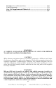
Find Streets or Intersections.................................................... 175 Find Waypoints......................................................................... 179 Sec. 10: Supplemental Material.......................................... 181 Index......................................................................................... 187 WARNING! A CAREFUL NAVIGATOR NEVER RELIES ON ONLY ONE METHOD TO OBTAIN POSITION INFORMATION.
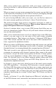
Section 1: Read Me First! How this manual can get you out on the road, fast! Welcome to the exciting world of digital sonar and GPS! We know you're anxious to begin navigating and finding fish, but we have a favor to ask. Before you grab the unit and begin installing it, please give us a moment or two to explain how our manual can help you get the best performance from your compact, wide-screen, combination fish finder and mapping GPS receiver. First, we want to thank you for buying an Eagle sonar/GPS unit.
After you've gained some experience with your sonar, you'll want to check out Section 4, which discusses more advanced Sonar Options and Other Features. When you come to a sonar menu command on the screen, you can look it up in the manual by skimming over the table of contents, just flipping through Section 3 or scanning through the sonar options in Section 4. If you're having difficulty with your sonar, you can find an answer to the most common problems in Section 5, Sonar Troubleshooting.
Now, if you're into the fine details, glance over the next segment on specifications to see just how much sonar and GPS power your unit contains. It's important to us (and our power users), but, if you don't care how many watts of power the unit has, or how many waypoints it can store, skip ahead to important information on how our sonar works, on page 5. (Background on GPS begins on page 6.) Capabilities and Specifications: FishElite 480 and SeaCharter 480DF General Display:............................
with built-in temperature sensor is packed with the FishElite 480. It has a 20º cone angle. Transducers operate at speeds up to 70 mph (61 kts). Transmitter: ................... 1,500 watts peak-to-peak/188 watts RMS. Sonar sounding depth capability: ........... SeaCharter 480DF: 1,500 feet (457 meters). FishElite 480: 800 feet (244 meters). Actual capability depends on transducer configuration and installation, bottom composition and water conditions.
Mapping memory: ......... Up to 256 MB on one MMC (or SD) card. Position updates: .......... Every second. Position points: ............. 1,000 waypoints; 1,000 event marker icons. Audible alarms: ............. Arrival/off-course/anchor. Graphic symbols for waypoints or event marker icons: ................. 42. Routes:............................. 100, up to 100 waypoints per route. Plot Trails: ...................... 10 savable; up to 10,000 points per trail. Zoom range:.................... 39 ranges; 0.
chart. The sonar's microprocessor calculates the time lapse between the transmitted signal and echo return to determine the distance to the object. The whole process repeats itself several times each second. Your unit can record a log of the sonar signals that scroll across the screen and save them to the MMC memory card. (These recordings are also called sonar charts or sonar graphs.
The background map is suitable for many navigation chores, but for maximum accuracy and much more detail, you need either our optional map-making software, MapCreate 6 or a predefined FreedomMap from LEI (no PC necessary!). Some unit features — such as searching for businesses and addresses — won't work without a custom MapCreate map or FreedomMap. There is so much detail in our background map (and even more in MapCreate and FreedomMaps) that we'll describe their contents and differences in Sec.
You make your own Custom Map Files with our MapCreate software, but you don't have to. We also sell ready-to-use FreedomMaps. These custom maps are pre-loaded on MMCs. (No computer work required!). This unit automatically reads Custom Map Files or FreedomMaps directly from the MMC or SD card. To use a custom map, all you need to do is slide an MMC containing a map into the unit. Introduction to GPS and WAAS Well, now you know the basics of how your unit does its work.
A minimum of three satellites are required to determine a 2D fix. The system requires signal reception from three satellites in order to determine a position. This is called a 2D fix. It takes four satellites to determine both position and elevation (your height above sea level — also called altitude). This is called a 3D fix. Remember, the unit must have a clear view of the satellites in order to receive their signals. Unlike radio or television signals, GPS works at very high frequencies.
However, there are some fringe areas of the U.S., including parts of Alaska, that do not yet receive robust WAAS coverage. Continued WAAS development is planned to extend WAAS coverage in the years to come. WAAS boosts the accuracy of land GPS navigation, but the system is designed for aircraft. The satellites are in a fixed orbit around the Equator, so they appear very low in the sky to someone on the ground in North America.
Menu Commands A menu command or a menu option will appear in small capital letters, in a bold sans serif type like this: ROUTE PLANNING. These indicate that you are to select this command or option from a menu or take an action of some kind with the menu item. Text that you may need to enter or file names you need to select are show in italic type, such as trail name.
Notes 12 www.Busse-Yachtshop.de email: info@busse-yachtshop.
Section 2: Installation & Accessories Preparations You can install the sonar and GPS systems in some other order if you prefer, but we recommend this installation sequence: Caution: You should read over this entire installation section before drilling any holes in your vehicle or vessel! 1. Determine the approximate location for the sonar/GPS unit, so you can plan how and where to route the cables for the antenna, transducer and power.
Read these instructions carefully before attempting the installation. Determine which of the mounting positions is right for your boat. Remember, the transducer installation is the most critical part of a sonar installation. Recommended Tools and supplies If you prefer the option of routing the cable through the transom, you will need either a 1" drill bit or a 5/8" drill bit depending on the type of cable connector (see page 22).
NOTE: Some aluminum boats with strakes or ribs on the outside of the hull create large amounts of turbulence at high speed. These boats typically have large outboard motors capable of propelling the boat at speeds faster than 35 mph. Typically, a good transom location on aluminum boats is between the ribs closest to the engine. 3. The transducer should be installed with its face pointing straight down, if possible.
How low should you go? For most situations, you should install your Skimmer transducer so that its centerline is level with the bottom of the boat hull. This will usually give you the best combination of smooth water flow and protection from bangs and bumps. Transom Transducer centerline Hull bottom Align transducer centerline with hull bottom. However, there are times when you may need to adjust the transducer slightly higher or lower.
However, the shoot-thru-hull installation does have its drawbacks. First, some loss of sensitivity does occur, even on the best hulls. This varies from hull to hull, even from different installations on the same hull. This is caused by differences in hull lay-up and construction. Second, the transducer angle cannot be adjusted for the best fish arches on your sonar display. (This is not an issue for flasher-style sonars.
B. Two-piece bracket: Locate the four plastic ratchets in the transducer's hardware package. Press two ratchets into the sides of the plastic bracket and two on either side of the transducer as shown in the following illustrations. Notice there are letters molded into each ratchet. Place the ratchets into the bracket with the letter "A" aligned with the alignment mark molded into the bracket.
hold it against the transom. Looking at the transducer from the side, check to see if it will adjust so that its face is parallel to the ground. If it does, then the "A" position is correct for your hull. If the transducer's face isn't parallel with the ground, remove the transducer and ratchets from the bracket. Place the ratchets into the holes in the bracket with the letter "B" aligned with the dot stamped in the bracket. Reassemble the transducer and bracket and place them against the transom.
Lock washer Bolt Nut Flat washer Flat washer Assemble transducer and bracket. 3. Assembling the transducer. A. One-piece bracket: Once you determine the correct position for the ratchets, assemble the transducer as shown in the following figure. Don't tighten the lock nut at this time. Metal washer Nut Rubber washers Metal washer Bolt Assemble transducer and bracket. B.
Transom Transom Position transducer mount on transom and mark mounting holes. Side view shown at left and seen from above at right. 5. Attaching transducer to transom. A. One-piece bracket: Remove the transducer from the bracket and re-assemble it with the cable passing through the bracket over the bolt as shown in the following figures. For single-frequency Skimmer, route cable over bolt and through bracket. Side view shown at left and seen from above at right.
Bottom of hull Flat-bottom hull Deep-"vee" hull Align transducer centerline with hull bottom and attach transducer to transom. Rear view of dual-frequency Skimmer shown. 6. Route the transducer cable through or over the transom to the sonar unit. Make sure to leave some slack in the cable at the transducer. If possible, route the transducer cable away from other wiring on the boat.
hole with the same marine grade above- or below-waterline sealant used for the mounting screws. 7. Make a test run to determine the results. If the bottom is lost at high speed, or if noise appears on the display, try sliding the transducer bracket down. This puts the transducer deeper into the water, hopefully below the turbulence causing the noise. Don't allow the transducer bracket to go below the bottom of the hull! TROLLING MOTOR BRACKET INSTALLATION (single-frequency only) 1.
TRANSDUCER ORIENTATION AND FISH ARCHES If you do not get good fish arches on your display, it could be because the transducer is not parallel with the ground when the boat is at rest in the water or at slow trolling speeds. Partial fish arches Transducer aimed too far back Transducer aimed too far forward Full fish arch Proper transducer angle Transducer angles and their effects on fish arches.
(such as plywood, balsa wood or foam) between layers of fiberglass if the material is removed from the chosen area. See the figure below. WARNING: Do not remove any material from your inner hull unless you know the hull's composition. Careless grinding or cutting on your hull can result in damage that could sink your boat. Contact your boat dealer or manufacturer to confirm your hull specifications.
To choose the proper location for shoot-thru-hull mounting, follow these testing procedures: (You may need a helper to complete these steps.) 1. Anchor the boat in about 30 feet of water. Add a little water to the sump of the boat. Plug the transducer into the sonar unit, turn it on, then hold the transducer over the side of the boat in the water. Adjust the sensitivity and range controls until a second bottom echo is seen on the display. (You'll need to turn off Auto Sensitivity, Auto Depth Range and ASP.
4. Most people can get good results by following steps 1 through 3, so this step is optional. If you want to make an extra effort to be absolutely sure that your selected location will work under all conditions, make a test run with the boat on plane and observe the bottom signal. You'll need to figure some way to prop the transducer into position while you make your test run. (A brick or two might be sufficient to hold it in place.) 5.
2. The epoxy consists of the epoxy itself and a hardener. Remove the two compounds from the package and place them on the paper plate. Thoroughly stir the two compounds together until the mixture has a uniform color and consistency. Do not mix too fast or bubbles will form in the epoxy. After mixing, you have 20 minutes to complete the installation before the epoxy becomes unworkable. Spread a thin layer of epoxy (about 1/16" or 1.5 mm thick) on the face of the transducer as shown in the previous figure.
If a second temp sensor is used, it must be the model TS-2U for the FishElite and the model TS-2X for the SeaCharter. These sensors have a fixed electronic "address" which designate them as the second of two temp sensors. See the following wiring diagrams for temperature and speed sensor combinations by unit. FishElite 480 Sensor Chart FishElite 480 rear view TS-2U temperature sensor Power/transducer cable Temperature sensor built into transducer FishElite 480 with secondary external temperature sensor.
SeaCharter 480DF Sensor Chart SeaCharter 480DF rear view SPY-X Speed Sensor with second connector Single-temperature sensor installation MY-4X Cable (optional) Temperature sensor built into transducer Transducer connector Two-temperature sensor installation TS-2X temperature sensor (optional) Three-temperature sensor installation TS-3X temperature sensor (optional) Optional Speed Sensor Installation All the units in this family can display speed and distance traveled, but only the SeaCharter 480DF co
Recommended tools for this job include: drill, 5/8" or 7/8" drill bit, 1/8" drill bit for pilot holes, screwdriver. Required supplies for this job include: four #8 stainless steel wood screws (3/4" long), high quality, marine grade above- or below-waterline sealant. Some equipment depends on your sensor model. See page 32 for details. First find a location on the boat's transom where the water flow is smoothest. Don't mount the sensor behind strakes or ribs.
Route the sensor's cable through or over the transom to the sonar unit. If you need to drill a hole in the transom to pass the connector through, the required hole size will depend on the connector on the end of your sensor's cable. If the sensor has a manual locking collar connector, you will need to drill a 7/8" hole. If it has a push-on self-sealing connector, you will need to drill a 5/8" hole. Manual locking collar connector requires a 7/8" hole. Push-on self-sealing connector requires a 5/8" hole.
to the unit, plug it in the center socket on the back and your system is ready to use. See the module's instruction sheet, publication part number 988-0148-37, for complete installation directions. In an automobile, you may achieve good results by simply placing the external antenna on the top of the dash, at the base of the windshield. A piece of the rubber non-skid shelf liner material available in recreational vehicle supply stores will help hold the antenna in place.
Optional power off switch for saltwater installations To FishElite 480 Red wire with 3 amp fuse To SeaCharter 480DF Black wire 12 volt battery 12 volt battery Black wire Power connections for the FishElite 480 (shown left) and SeaCharter 480DF (shown right) sonar/GPS units. WARNING: This product must be independently fused with the enclosed 3-amp fuse (or equivalent), even if you connect to a fused accessory or power buss.
tem's operation in the United States. Since it's creation, DGPS has become the international maritime standard for marine navigation. The most popular DGPS system relies on a grid of ground-based transmitters that send correction signals to DGPS receivers. These in turn, connect to the GPS receiver (such as the SeaCharter 480DF). Eagle offers an optional DGPS receiver for your unit. See the diagrams on the following page for general wiring connections.
GPS socket SeaCharter 480DF, rear view Sonar socket Com port data wires (three) Power/Data socket Transducer Power wires (two) GPS antenna module SeaCharter 480DF cable connections. GPS socket FishElite 480, rear view Accessory socket Sonar/Power socket Power wires Transducer GPS antenna module FishElite 480 cable connections. 36 www.Busse-Yachtshop.de email: info@busse-yachtshop.
Mounting the Unit: Bracket, In-Dash or Portable You can install the unit on the top of a dash with the supplied gimbal bracket. It can also be installed in the dash or mounted on a portable power supply. If you use the supplied bracket, you may be interested in the optional R-A-M bracket mounting system. This converts the unit's gimbal bracket to a swivel mount, which can be used on the dash or overhead mounting positions. Installation instructions are supplied with the R-A-M mounting kits.
Drill a 1-inch (25.4 mm) hole in the dash for the power, transducer and antenna cables. The best location for this hole is immediately under the gimbal bracket location. This way, the bracket can be installed so that it covers the hole, holds the cables in position and results in a neat installation. Some customers, however, prefer to mount the bracket to the side of the cable hole — it's a matter of personal preference. 72.9 [2.87] 173.9 [6.85] 137.9 [5.43] 23.4 [0.92] 157.9 [6.
In-Dash Installation You can mount the unit in the dash with an optional FM-5 In-Dash Adapter Kit. The kit includes mounting hardware, a template for cutting the hole and an instruction sheet, part 988-0147-43. 146.5 [5.76] Top R 7.9 [0.31] In-Dash Template 113.5 [4.46] Millimeters [Inches] ALWAYS VERIFY DIMENSIONS In-dash mounting template for this sonar/GPS unit, showing dimensions. NOTE: The figure above is not printed to scale.
"D" cell battery Install batteries in power pack battery adapter. MMC or SD Card Memory Card Installation Your sonar/GPS unit uses a MultiMedia Card to store information, such as sonar logs, custom maps, waypoints, trails and other GPS data. The unit can also use Secure Digital Cards (SD card or SDC) to store data. NOTE: Throughout this manual, we will use the term MMC, but just remember that your unit can use an MMC or SD card to store data.
Thumb screw Insert card face up, this way Memory card compartment with a 16 MB MMC card installed. To remove an MMC 1. Open the card compartment door by unscrewing the thumb screw. The screw should only be finger tight. If it was over-tightened, use a thumbnail, a coin or a screwdriver to open the door. 2. Just press a finger against the label of the MMC and drag it from the slot. 3. Close the compartment door and fasten the thumb screw finger tight. To add an MMC or SD Card 1.
MapCreate™ 6 CD-ROM, left; MMC card reader for USB ports, right. Now that you have your unit installed, move on to Sec. 3, Basic Sonar Operations. There, we'll present a series of step-by-step tutorials to teach you the basics of sonar operation. NOTE: When you first turn the unit on, the Map Page appears. If you'd rather start learning about GPS operation first, turn over to Sec. 6, Basic GPS Operations. (Remember, you don't need to read this manual from cover-to-cover to get going.
Section 3: Basic Sonar Operation This section addresses the unit's most basic sonar operations. The instructions presented in Sec. 3 follow a chronological order. Sec. 4, Sonar Options & Other Features, will discuss other more advanced functions and utilities. Material in Sec. 4 is arranged in alphabetical order. Before you turn on the sonar unit, it's a good idea to learn about the different keys, the Main Menu, the four Page screens and how they all work together.
4. ARROW KEYS – These keys are used to navigate through the menus, make menu selections, move the map and sonar chart cursors and enter data. 5. ENT/ICONS (Enter & Icons) – This key allows you to save data, accept values or execute menu commands. It is also used to create event marker icons. 6. EXIT – The Exit key lets you return to the previous screen, clear data or erase a menu. 7. WPT – (Waypoint) The Waypoint key is used to save and recall waypoints, search for waypoints and access the waypoint list.
You can access the Main Menu from any of the four Page screens by pressing MENU|MENU. To clear the menu screen and return to the page display, press EXIT. (Remember, our text style for "MENU|MENU" means "press the Menu key twice." See a full explanation of our instruction text formatting on pages 10 and 11, "How to use this manual…". Main Menu. The Main Menu commands and their functions are: Screen command: changes the contrast or brightness of the display screen.
Timers command: controls the up timer, down timer and alarm clock settings. Browse MMC Files command: this allows you to view the installed MMC card and the files it contains. Pages The unit has four Page displays that represent the four major operating modes. They are the Satellite Status Page, the Navigation Page, the Map Page and Sonar Page. They are accessed by pressing the PAGES key, then using → or ← to select a Page. (Clear the Pages Menu by pressing EXIT.
Satellite Status Page showing satellite lock-on with a 3D position acquired (latitude, longitude and altitude), including WAAS reception. Navigation Page This screen has a compass rose that not only shows your direction of travel, but also the direction to a recalled waypoint. To get to the Navigation Page: Press PAGES| → or ← to NAVIGATION|EXIT. This page represents a GPS function, so it is discussed in much greater detail in Sec. 6. Navigation Page, recording a trail, traveling southwest.
Map Page, showing position on Bull Shoals Lake, Arkansas. At left is the full map option. At right, map with sonar option. Map Page is also the default screen that appears when you turn on the unit. To get to the Map Page from another page: Press PAGES| → or ← to MAP|EXIT. You can display a split screen showing both the Map and Sonar pages at the same time. This feature is discussed in Sec. 4, Sonar Options & Other Features.
At left, Pages Menu, showing sonar chart display option commands. At right, Sonar Page in full sonar chart display mode. Sonar chart display options (from left) split zoom and split frequency. At left, digital data sonar chart display options. At right, Sonar Page Menu. Most of these functions are discussed in Sec. 4. 49 www.Busse-Yachtshop.de email: info@busse-yachtshop.
Digital data overlay (depth & temperature) Surface signal Surface clutter Depth scale In FasTrack, fish arches show as horizontal bars. Fish arches Zoom bar Structure FasTrack bar graph Bottom signal Sonar Page, showing full sonar chart mode. You can customize how the Sonar Page displays its pictures and other data in many ways. Your unit also includes several special sonar features and options that can help you better interpret the underwater scene.
Basic Sonar Quick Reference 1. Mount the transducer, antenna and unit. Connect the unit to electric power and the transducer. (If GPS operation is desired, connect GPS antenna, too.) Make sure the MMC is in. (See complete installation details beginning on page 13.) 2. Launch your boat. 3. To turn on the unit, press and release PWR key. 4. Opening screen displays Map Page.
Sonar Operations As you can see from the quick reference on the previous page, basic operation is pretty easy, right out of the box. If you are a sonar novice, try operating the unit with the factory defaults until you get a feel for how it's working. As you're learning the basics, there is one setting you might want to tinker with from time to time — Sensitivity. Sensitivity controls the unit's ability to pick up echoes. If you want to see more detail, try increasing the sensitivity, a little at a time.
You can change the sensitivity level whether you are in Auto Sensitivity mode or Manual Sensitivity mode. The adjustment method works the same in both modes, but it gives you slightly different results. Adjusting sensitivity in Auto Sensitivity Mode is similar to manually adjusting a car's speed with the accelerator pedal while cruise control is on. You can tell the car to run faster, but when you let off the gas the cruise control automatically keeps you from running slower than the minimum speed setting.
NOTE: If you want to change the sensitivity in Manual Mode, first turn off Auto Sensitivity: from the Sonar Page, press MENU|↓ to AUTO SENSITIVITY|ENT|↑ to SENSITIVITY|ENT. Press ↓ or ↑ to pick a different sensitivity setting. When it's set at the desired level, press EXIT. Important Tip: While you are experimenting and learning, it's possible to scramble the settings so that the sonar picture disappears from your screen.
Other Free Training Aids The sonar options section discusses Fish I.D., fish alarms and other features in greater detail. If you or a friend has Internet access, you can also learn more about interpreting what you see on your sonar screen. Visit our web site, WWW.EAGLESONAR.COM. Be sure to check out the free Sonar Tutorial, which includes animated illustrations and more pictures of actual sonar returns, all described in detail.
Free training emulator is available for your unit on our web site. The emulator works exactly like your real sonar/GPS unit. Using the Sonar Simulator and GPS Simulator features, it allows you to play back sonar logs, run GPS routes and trails, even create real waypoints you can use in the field! You can even take snapshots of the Sonar Chart and print them or e-mail them to friends. 56 www.Busse-Yachtshop.de email: info@busse-yachtshop.
Section 4: Sonar Options & Other Features Material in this section is arranged in alphabetical order. ASP (Advanced Signal Processing) The ASP feature is a noise rejection system built into the sonar unit that constantly evaluates the effects of boat speed, water conditions and interference. This automatic feature gives you the best display possible under most conditions. The ASP feature is an effective tool in combating noise. In sonar terms, noise is any undesired signal.
Alarms This unit has three different types of sonar alarms. The first is the Fish Alarm. It sounds when the Fish I.D. feature determines that an echo is a fish. Another alarm is the Zone Alarm, which consists of a bar on the side of the screen. Any echo on the chart that appears inside this bar triggers this alarm. The last alarm is the Depth Alarm, which has both a Shallow and a Deep setting. Only the bottom signal will trigger this alarm.
5. To turn off the alarm, press MENU|MENU|↓ to ALARMS|ENT|↓ to SONAR ALARMS|ENT|ENT|EXIT|EXIT|EXIT. To switch to a different depth setting, open the Sonar Alarms menu and repeat the instructions in step 3 above. To adjust and turn on the deep alarm: 1. Press MENU|MENU|↓ to ALARMS|ENT|↓ to SONAR ALARMS|ENT. 2. Press ↓ to DEEP ALARM ENABLED|→ to DEEP ALARM DEPTH|ENT. 3.
5. Press EXIT|← to ZONE ALARM ENABLED|ENT|EXIT|EXIT|EXIT. Now, any echo — fish, bottom, structure — within the zone alarm's depth range will trigger the zone alarm. 6. To turn off the alarm, press MENU|MENU|↓ to ALARMS|ENT|↓ to SONAR ALARMS|ENT|↓ to ZONE ALARM ENABLED|ENT|EXIT|EXIT|EXIT. To switch to a different depth setting, open the Sonar Alarms menu and repeat the instructions in steps 3 and 4 above.
When you make a run to compare GPS ground speed to speed sensor speed, perform your test in relatively calm water free of current, if possible. (Unless, of course, you are taking the current speed into consideration when making your calculation.) After you have a correction figure, here's how to enter it: 1. Press MENU|MENU|↓ to SONAR SETUP|ENT|↓ to CALIBRATE WATER SPEED|ENT. 2.
1. From the Sonar Page, press MENU|↓ to CHART SPEED|ENT. 2. The Chart Speed Control Bar appears. Press ↓ to decrease chart speed; press ↑ to increase chart speed. 3. When it's set at the desired level, press EXIT. Depth Cursor The depth cursor consists of a horizontal line with a digital depth box on the right side. The numbers inside the box show the depth of the cursor. Cursor line Depth box At left, Sonar Page menu with Depth Cursor command selected. At right, sonar chart with the depth cursor active.
At left, Sonar Page menu with Depth Range command selected. At right, the Depth Range Control Scale. 2. The Depth Range Control Scale appears. Press ↑ or ↓ to select a different depth range. A black bar highlights the selected range. Range numbers in gray cannot be selected. 3. When the new range is selected, press EXIT to clear the menu. Depth Range - Manual You have complete control over the range when the unit is in the manual mode. There are 16 depth ranges, from 5 feet to 4,000 feet.
Surface clutter Fish arches Structure In FasTrack, fish arches show as horizontal bars. Grayline Bottom signal Sonar Page showing FasTrack. FasTrack bar graph Fish I.D. (Fish Symbols & Depths) The Fish I.D. feature identifies targets that meet certain conditions as fish. The microcomputer analyzes all echoes and eliminates surface clutter, thermoclines, and other signals that are undesirable. In most instances, remaining targets are fish. The Fish I.D.
Sonar Features menu with Fish I.D. Symbols selected (at left, dualfrequency menu; at right, single-frequency menu). When the check box to the left is checked, the feature is on. Fig. 1 A Fig. 1 B Many fish arches visible Fewer fish symbols visible Fig. 2 A Fig. 2 B Fish arches above structure No fish shown FasTrack graph confirms fish above structure At left, figures 1A and 2A show Sonar Page in normal chart mode. At right, figures 1B and 2B show the same underwater scene with Fish I.D. turned on.
To turn the Fish I.D. feature on: 1. From the Sonar Page, press MENU|↓ to SONAR FEATURES|ENT. 2. Press → to FISH SYMBOLS|ENT|EXIT|EXIT. To turn off Fish I.D., repeat the instructions in step 2. FishTrack The FishTrack feature shows the depth of a fish symbol when it appears on the display. This lets you accurately gauge the depth of targets. This feature is available only when the Fish I.D. feature is on. The default setting for FishTrack is off.
clines – are also emphasized. This can make it hard to distinguish fish signals inside thermoclines or other cover. In FishReveal mode, the weakest echoes are white and the strongest echoes are black. Echoes in between vary in gray in proportion to their signal strength. The Grayline control determines the range for black to white. Also note that when using FishReveal, we recommend that you turn off Auto Sensitivity and turn up Sensitivity to near maximum.
NOTE: Water conditions vary greatly, and that affects sonar performance. Under certain conditions, FishReveal will show you more fish than normal grayscale mode, but the reverse will be true in other circumstances. We suggest you become familiar with both modes so you can best match your sonar's performance to the current water conditions. Frequency (Change Transducer Frequency) (SeaCharter 480DF only) The SeaCharter 480DF transducer operates with both 200 kHz and 50 kHz.
To change the frequency setting to 50 kHz: 1. From the Sonar Page, press MENU|↓ to SONAR FEATURES|ENT. 2. Press →|then press ↓ to 50 KHZ|ENT. 3. Press EXIT|EXIT to clear the menu. To change the frequency setting to 200 kHz: 1. From the Sonar Page, press MENU|↓ to SONAR FEATURES|ENT. 2. Press →|then press ↓ to 200 KHZ|ENT. 3. Press EXIT|EXIT to clear the menu. Grayline Grayline lets you distinguish between strong and weak echoes. It "paints" gray on targets that are stronger than a preset value.
3. When it's set at the desired level, press EXIT. Fig. 1A Fig. 1B Hard structure Fish near structure Grayline Fig. 2A Fig. 2B Hard bottom Muddy bottom Grayline Fig. 3A Fig. 3B Muddy bottom Hard bottom Grayline This series of figures shows how different Grayline settings can reveal more information. The "A" figures to the left show locations with Grayline set at the factory level of 64 percent. At right, the "B" figures show the same locations with Grayline increased to 84 percent.
HyperScroll See the entry on Ping Speed, which controls the HyperScroll feature. Log Sonar Chart Data If you have an MMC installed in the unit, the sonar data shown on the screen can be saved to the MMC. This can be played back at any time (to play a recorded sonar chart log, see the entry in this section for Sonar Simulator). If you have a personal computer and Internet access, visit our web site, www.eaglesonar.com, and download the free Sonar Viewer and the emulator for your unit.
Overlay Data To change the digital data shown "floating" on top of the Sonar Page or the Map Page: First, press PAGES, use → or ← to select a Page Name, then press EXIT. To select data for display: 1. From the Map or Sonar page, press MENU|↓ to OVERLAY DATA|ENT. 2. Press ↓ or ↑ to select Data Type|ENT. Overlay Data command on the Sonar Menu, at left. Overlay Data Shown selection menu, right. In this example, we scrolled down the data list to highlight "Ground Speed.
2. Press ↓ or ↑ to select Data Type|ENT. The selected data type disappears from the top of the list and reverts to its previous, unchecked position. (If you wish, you may now use ↓ or ↑ to select other Data Types to turn off.) 3. To return to the previous page, press EXIT|EXIT. To change displayed data font size: 1. From the Map or Sonar page, press MENU|↓ to OVERLAY DATA|ENT. 2. Press ↓ or ↑ to select Data Type|press → or ← to Data Size|EXIT. The selected data type will be displayed in the new size.
NOTE: Some data types can be displayed in only one font size. If that is the case, the Data Size box will not be displayed for that data type. Ping Speed & HyperScroll Ping Speed controls the rate at which the transmitter and transducer broadcast sonar sound waves — pings — into the water. The unit has a default ping speed of 50 percent. At normal boating speeds, this automatically provides enough return echoes to refresh the screen and scroll the chart at maximum chart speed.
To adjust Sensitivity: 1. From the Sonar Page, press MENU|ENT. 2. The Sensitivity Control Bar appears. Press ↓ to decrease sensitivity; press ↑ to increase sensitivity. When it's set at the desired level, press EXIT. (When you reach the maximum or minimum limit, a tone sounds.) To turn off HyperScroll: 1. From the Sonar Page, press MENU|↓ to PING SPEED|ENT. 2. The Ping Speed Control Bar appears. Press↓ to decrease ping speed to 50 percent. When it's set at the desired level, press EXIT.
NOTE: Reset Options does not erase any waypoints, routes, plot trails, or sonar logs. Reset Water Distance The sonar chart's Digital Data display option includes a box that shows distance traveled, called Water Distance. This information is calculated from an optional water speed sensor, not the GPS. The Water Distance window can be reset to zero using the Reset Water Distance command. Press MENU|MENU|↓ to SONAR SETUP|ENT|↓ to RESET WATER DISThe menus are cleared and the water distance is reset to 0.00.
ter depth from surface to bottom. To do this, first measure the distance from the face of the transducer up to the surface (the water line on the boat). In this example, we will use 1.5 feet. This will be entered as a positive 1.5 feet, which makes the depth indicators perform as if the transducer's higher in the water than it really is. 1. Press MENU|MENU|↓ to SET KEEL OFFSET|ENT. 2. The Keel Offset dialog box appears with a plus (+) sign at the front of the box. 3.
In manual mode, you have complete control over sensitivity, with the ability to set it anywhere from zero to 100 percent. Once you select a level in manual, the unit will continue to use that exact sensitivity setting until you change it or revert to auto mode. To adjust sensitivity in auto mode: 1. Press MENU|ENT. 2. The Sensitivity Control Bar appears. Press ↓ to decrease sensitivity; press ↑ to increase sensitivity. When it's set at the desired level, press EXIT.
changes on the screen as you press the up or down arrows. This is handy when there's a lot of clutter in the water, and you are matching the sensitivity to rapidly changing water conditions. Sonar Color Mode The default color scheme for the sonar chart is grayscale, but we offer other variations to suit your viewing preferences. You can select the chart to be displayed in reverse grayscale, bottom black or FishReveal mode.
bottom depth and surface temperature (if equipped with a temperature sensor or a transducer with a temp sensor built in) show at the top left corner of the screen. The FasTrack™ display shows just to the right of the scale. This changes all echoes into short horizontal bars, replicating a flasher sonar. The zoom bar on the far right shows the area that's zoomed when the zoom is in use. (See the Zoom section for more information.) Full Sonar Chart.
Split Frequency Sonar Chart (SeaCharter 480DF only) This page shows sonar data from the 50 kHz transducer element on the left side of the screen and data from the 200 kHz transducer on the right side. All other functions and features are the same as the Full Chart page. Split Frequency Sonar Chart page, with 50 kHz view at left and 200 kHz view at right. You can adjust the sensitivity in each window. To adjust sensitivity in auto mode: 1. Press MENU|ENT. 2. The unit asks which you wish to adjust.
Digital Data/Chart This mode shows the chart on the right side of the screen. The left side has seven large digital data boxes or windows containing: Water Depth; Water Speed (from an optional speed sensor); Water Distance (distance traveled or log, it also requires a speed sensor); Surface Water Temperature; Temperature #2, Temperature #3 and Voltage. (Note: Temperature #2 and #3 require additional optional temperature sensors.
Options List for customizing Digital Data boxes. At left, the list first appears with Water Speed selected. At right, Maximum Speed has been picked to replace Water Speed in the top digital data box. Tip: You can customize other digital data boxes before returning to the Sonar Page. After changing the first box by selecting the Data Type and pressing Enter, use the ↓ key to select another box to change. When the selected box title bar flashes, press ENT|↑ or ↓ to select data type|ENT.
PAGES|PAGES. The window with the black title bar at the top of the screen is the active window. To switch back, just press PAGES|PAGES again. Sonar Simulator This unit has a built-in simulator that lets you run it as if you were on the water. All sonar features and functions are useable. When in simulator mode, you will see the chart file name in the Sonar Page title bar and a play symbol will flash on and off at the right end of the title bar. To use the simulator: 1.
Title bar with chart file name "Play" symbol flashing Sonar Page, playing a recorded sonar chart in Sonar Simulator mode. Tip: The Sonar Simulator can use sonar charts that you or a friend have recorded (logged) on an MMC card. (To see how, read the entry in this section on Log Sonar Chart Data.) To play back your own sonar chart, make sure the MMC containing the chart is installed, then: 1. Press MENU|MENU|↓ to SONAR SETUP|ENT|↓ to SONAR SIMULATOR|ENT. 2. Press ↓ to CHART USED|ENT. 3.
Menu sequence for playing a sonar chart log from the MMC File List. NOTE: For some great practice, try running the Sonar Simulator and the GPS Simulator at the same time. This will really give you a feel for how the unit will work in the field. NOTE: If you turn on your unit before attaching a transducer, it may enter a demo mode. The words "demo mode" flash on the bottom of the screen and a sonar chart plays much like the simulator.
Surface Clarity The markings extending downward from the zero line on the chart are called "surface clutter." These markings are caused by wave action, boat wakes, temperature inversion and more. The surface clarity control reduces or eliminates surface clutter signals from the display. It does this by changing the sensitivity of the receiver, decreasing it near the surface and gradually increasing it as the depth increases. There are three levels of surface clarity available: low, medium, or high.
Zoom & Zoom Bar "Zooming" the display is a common, fast and easy method used to enlarge small detail, fish signals and the bottom with its associated structure. This unit lets you zoom the display quickly and easily by pressing the Zoom In key, ZIN. Pressing ZIN once doubles the size (2X) of all echoes on the screen. Pressing it again quadruples the size of the echoes (4X). The zoom bar on the far right side of the screen shows which echoes will be displayed on the screen when the ZIN key is pressed.
Section 5: Sonar Troubleshooting If your unit is not working, or if you need technical help, please use the following troubleshooting section before contacting the factory customer service department. It may save you the trouble of returning your unit for repair. For contact information, refer to the last page, just inside the back cover of this manual. Unit won't turn on: 1. Check the power cable's connection at the unit. Also check the wiring. 2. Make sure the power cable is wired properly.
3. The water may be deeper than the sonar's ability to find the bottom. If the sonar can't find the bottom signal while it's in the automatic mode, the digital sonar display will flash continuously. It may change the range to limits far greater than the water you are in. If this happens, place the unit in the manual mode, then change the range to a realistic one, (for example, 0-100 feet) and increase the sensitivity. As you move into shallower water, a bottom signal should appear. 4.
To eliminate or minimize the effects of electrical noise, first try to determine the cause. With the boat at rest in the water, the first thing you should do is turn all electrical equipment on the boat off. Make sure the engine is also off. Turn your sonar on, then turn off Noise Reject [also known as the ASP feature (Advanced Signal Processing)]. Sensitivity should be set at 90-95 percent. There should be a steady bottom signal on the display.
Notes 92 www.Busse-Yachtshop.de email: info@busse-yachtshop.
Section 6: Basic GPS Operations This section addresses the unit's most basic GPS operations. The tutorials presented in Sec. 6 follow a chronological order. Sec. 7, Advanced GPS Operations, will discuss other more advanced functions and utilities. Material in Sec. 7 is arranged in alphabetical order. Before you turn on the unit and find where you are, it's a good idea to learn about the different keys, the four Page screens and how they all work together.
3. MENU – Press this key to show the menus and submenus, which allow you to select a command or adjust a feature. This also accesses search functions for streets, intersections, addresses and highway exits. 4. ARROW KEYS – These keys are used to navigate through the menus, make menu selections, move the map cursor and sonar chart cursor and enter data. 5. ENT/ICONS (Enter & Icons) – This key allows you to save data, accept values or execute menu commands. It is also used to create event marker icons. 6.
something. The GPS will work fine for these lessons right out of the box with the factory default settings. But, if you want to learn about the various options, see Sec. 8, System Setup and GPS Setup Options. You can access the Main Menu from any of the four Page screens by pressing MENU|MENU. To clear the menu screen and return to the page display, press EXIT. Main Menu. The Main Menu commands and their functions are: Screen command: changes the contrast or brightness of the display screen.
Sun/Moon Calculations command: finds the rising and setting time of the sun and the moon. Trip Calculator command: shows trip status and statistics. Timers command: controls the up timer, down timer and alarm clock settings. Browse MMC Files command: this allows you to view the installed MMC card and the files it contains. Pages The unit has four Page displays that represent the four major operating modes. They are the Satellite Status Page, the Navigation Page, Map Page and the Sonar Page.
No matter what Page you are on, a flashing current position indicator/question mark symbol and flashing GPS data displays indicate that satellite lock has been lost and there is no position confirmed. The Satellite Status Page shows you the quality and accuracy of the current satellite lock-on and position calculation. WARNING: Do not begin navigating with this unit until the numbers have stopped flashing! Satellite Status Page.
This also gives you an indicator of the fix quality the unit currently has. The smaller the position error number, the better (and more accurate) the fix is. If the position error flashes dashes, then the unit hasn't locked onto the satellites, and the number shown isn't valid. (For details, see the Customize Page Displays entry in Sec. 8.) The Satellite Status Page has its own menu, which is used for setting various options. (Options and setup are discussed in Sec. 8).
NOTE: Remember, when the Speed, Track and Position information displays are flashing, satellite lock has not been achieved and no position fix has been determined. A question mark will also flash on the present position arrow in the center of the compass rose. Speed (ground speed) is the velocity you are making over the ground. (If you wish, you can customize the Speed data box to display Closing Speed instead. Closing Speed is also known as velocity made good.
The cross track error range is shown on the compass rose as a wide, white, corridor enclosing the course line. The outer edges of this white corridor represent lines that show the current cross track error range. The default for the cross track error range is 0.20 miles. For example, if the present position symbol touches the right cross track error line, then you are 0.20 miles to the right of the desired course. You need to steer left to return to the desired course.
The arrow in the center of the screen is your present position. It points in the direction you're traveling. The solid line extending from the back of the arrow is your plot trail, or path you've taken. The map zoom range is the distance across the screen. This number shows in the lower right corner of the screen. In the first of the following example figures, the range is 4,000 miles from the left edge of the map to the right edge of the map.
Map Pages with high-detail MapCreate map of an urban area loaded on the MMC. At left, arterial streets appear at the 4 mile zoom range, with a few Point of Interest icons visible. Center, numerous dots representing Points of Interest are visible at the 2 mile range, along with minor streets. Right, at the 0.4 mile zoom, you can see an interstate highway with an exit, major and minor streets as well as Point of Interest icons. Background map vs.
NOTE: Available through LEI Extras (look inside back cover for accessory ordering information), FreedomMaps are pre-made maps that contain all of the same information available in a custom MapCreate map, without any of the work of preparation. Interstate Major Street Cursor line Minor Streets POI Pop-up POI Marker Restaurant POI School POI Position, distance and bearing data Zoom Range When the map is zoomed out far enough, most POIs appear as square dots.
At left, Digital Data map page; at right, Two Position Formats page. In pages that have two major windows (such as two maps) you can toggle back and forth between the two windows by pressing PAGES|PAGES. This allows you to change which map your cursor moves on, and which map the menu operates on. A black title bar denotes the active window. Pages Menu with Two Map option selected, left. Map Page with two map windows, at right. The left map is active.
Basic GPS Quick Reference Start outdoors, with a clear view of the open sky. As you practice, try navigating to a location at least a few blocks away. While you're learning, navigation in too small an area will constantly trigger arrival alarms. 1. Connect the unit to electric power and the antenna module. Make sure the MMC is in. (See complete installation details beginning on page 13.) 2. To turn on the unit, press and release PWR key. 3.
Find Your Current Position Finding your current position is as simple as turning the unit on. Under clear sky conditions, the unit automatically searches for satellites and calculates its position in approximately one minute or less. NOTE: "Clear sky" means open sky, unobstructed by terrain, dense foliage or structures. Clouds do not restrict GPS signal reception. If for some reason satellite acquisition takes longer, you may be inside a structure or vehicle or in terrain that is blocking signal reception.
Cursor line Cursor line Selected airport POI pop-up data box Distance measured by cursor The selected airport to the northwest is 4.2 miles away. Selecting Any Map Item With the Cursor 1. Use the zoom keys and the arrow keys to move around the map and find the item you wish to select. 2. Use the arrow keys and center the cursor cross-hair on the desired object. On most items, a pop-up box will give the name of the selected item.
2. You could search the entire restaurant category, but in this example we will narrow our search. Press → to SUBCATEGORY column|↓ to FAST FOOD CHAINS|ENT|↓ to NEAREST|ENT. 3. The unit says it is calculating, then a list of restaurants appears, with the closest at the top of the list, and the farthest at the bottom of the list. The nearest is highlighted. Find Waypoint Menu, left; Category Selection menu, center; and list of the nearest restaurants, right. 4.
6. The unit's map appears, with the cross-hair cursor highlighting the restaurant' s POI symbol. A pop-up data box shows the POI's name, distance and bearing. A data box at the bottom of the screen continues to display the location's latitude and longitude. Map screen showing Finding Waypoint, the result of a restaurant search. 7. To clear the search and return to the last page displayed, press EXIT|EXIT|EXIT|EXIT.
Create Waypoint at Current Position While you are traveling, press WPT|WPT. The waypoint is saved and automatically given a name with a sequential number, such as "waypoint 003." The waypoint symbol and number appear on the map. Step 1. Step 2. Step 3. Step 4. Sequence for setting a waypoint. Step 1: while traveling, quickly press WPT twice to call up Find Waypoint screen (seen in Step 2) and set a point. Step 3: a message says the waypoint has been saved.
Create Waypoint on Map 1. Use the arrow keys to move the cursor to the place where you want to make a waypoint. 2. Press WPT|WPT. The waypoint is saved and automatically given a name with a sequential number, such as "waypoint 001." The waypoint symbol and number appear on the map. Create Waypoint by Entering a Position 1. Press WPT|→ to SUBCATEGORY column|↓ to NEW|ENT. 2. Press ↓ to ENTERED POSITION|ENT|→ to CREATE|ENT. 3. Press → to LATITUDE|ENT.
Waypoint Course line (dotted) Trail line (solid) Off course range, set at 0.20 mile Destination name Navigation Page, navigating toward waypoint 004 and leaving a trail. Set Man Overboard (MOB) Waypoint One of boating's most terrifying events is having a friend or family member fall overboard. This situation can be deadly on any body of water — fresh or salt. It's particularly dangerous at night or if you're out of sight of land.
Navigating to Man Overboard: Man Overboard Activated message, left, Navigation Page, center, Map Page, right. The victim is to the starboard of the vessel; the GPS shows which direction to steer to for the rescue. The man overboard position is also stored in the waypoint list for future reference. It can be edited the same as any other waypoint. This prevents the inadvertent loss of the current Man Overboard position. To cancel navigation to MOB, press MENU|MENU|↓ to CANCEL NAVIGAto YES|ENT.
3. Press MENU|ENT and the unit will begin navigating to the cursor location. The Map Page will display a dotted line from your current position to the cursor position. The Navigation Page displays a compass rose showing navigation information to your destination. See the following examples. The 15-mile zoom figure at left clearly shows the dotted course line connecting your current position to your destination. The 40-mile zoom, center, shows both current position and destination on screen.
particularly handy when you are trying to retrace your trip and go back the way you came. On the screen, trails are represented by a solid line extending from the back of the current position arrow. The unit is set at the factory to automatically create and record a trail while the unit is turned on. The unit will continue recording the trail until the length reaches the maximum trail point setting (default is 2,000, but the unit can record trails 9,999 points long).
New trail, named "Trail 15," is created when Trail 14 is made inactive. Any new travel will be recorded in this trail, which is active and visible. Trails do not need to be visible in order to be active. You can save and recall up to 10 different plot trails, which can also be copied to your MMC for archiving or for transfer to your MapCreate software. Tip: Another quick way to stop recording one trail and begin a new one is to use the New Trail command: Press MENU|MENU|↓ to MY TRAILS|ENT|ENT.
To turn on trail display: 1. Press MENU|MENU|↓ to MY TRAILS|ENT. 2. Press ↓|↓ to enter the Saved Trail list, then use ↑ or ↓ to select the desired Trail Name|ENT. 3. Press ↓ to ACTIVE|→ to VISIBLE|ENT. To return to the previous page, press EXIT|EXIT|EXIT|EXIT. Navigating Trails There are three methods for following a trail: visual trailing, navigating a trail (forward) and backtracking a trail (backward). Try each method to see which you prefer. Visual trailing is the simplest method.
3. Press → to DELETE TRAIL|↓ to NAVIGATE|ENT. 4. Press ↓ to NAVIGATE|ENT. The unit begins showing navigation information along the trail. NOTE: If you are already located at or near the beginning of your trail, the arrival alarm will go off as soon as you hit Enter. Just press EXIT to clear the alarm and proceed. 5. Now, begin moving and follow your unit. 6. When you reach your destination, be sure to cancel your navigation: press MENU|MENU|↓ to CANCEL NAVIGATION|ENT.
North Present position arrow Trail point Trail dotted line Navigate trail, map views: at left driver is northbound heading straight toward trail point 6. At right, northbound driver has reached point 6 and has turned west to follow trail.
NOTE: If you are already located at or near the end of your trail, the arrival alarm will go off as soon as you hit Enter. Just press EXIT to clear the alarm and proceed. 5. Now, begin moving and follow your unit. 6. When you reach your destination, be sure to cancel your navigation: press MENU|MENU|↓ to CANCEL NAVIGATION|ENT. The unit asks if you're sure; press ←|ENT. Transfer Custom Maps and GPS Data Files Custom Maps: Custom maps work only from the MMC card or SD card.
The Transfer My Data submenu asks if you want to save data to the MMC or load data from the MMC into the unit's memory. 2. The Transfer My Data menu includes a message which tells you if an MMC is present or not. If no MMC is present, you must first insert a card into the unit in order to activate the Load or Save commands. To transfer data from the unit to the MMC: press ENT (for SAVE.) To transfer data from the MMC to the unit: press → to LOAD|ENT. 3.
4. Loading to unit memory: There may be more than one GPS Data File (*.USR) on the card. To select a file, press ENT to activate the selection box, use ↓ or ↑ to highlight the file, then press ENT to accept the selection. Next, press ↓ to LOAD DATA|ENT. The unit will display a completion message when the data transfer is finished. To return to the Page view, press EXIT|EXIT|EXIT|EXIT. Figure 1. Figure 2. Figure 3. Figure 4.
Section 7: Advanced GPS Operations Find Distance From Current Position To Another Location 1. While on the Map Page press: MENU|↓ to FIND DISTANCE|ENT. 2. Center your cursor over the position you want to find the distance to. A rubber band line appears, connecting your current position to the cursor's location. The distance along that line will appear in a pop-up box. The box also shows the bearing to the point you're measuring to. 3. Press EXIT to return to regular operation.
Icons Icons are graphic symbols used to mark some location, personal point of interest or event. They can be placed on the map screen, saved and recalled later for navigation purposes. These are sometimes referred to as event marker icons. This unit has 42 different symbols you can pick from when creating an icon. Icons are similar to waypoints, but they do not store as much information (like names) as waypoints do. You can't use a menu to navigate to icons as you can with waypoints.
1. Press MENU|↓ to DELETE MY ICONS|ENT. 2. Press ↓ to DELETE ALL ICONS, DELETE BY SYMBOL, or DELETE FROM MAP and press ENT. Delete icons menu. The Delete All Icons command will ask if you are sure. Press ← to YES|ENT. All icons will be deleted from the map. The Delete by Symbol command will launch the Select Symbol menu. Press ← or ↑ or → or ↓ to select the icon symbol to delete, then press ENT. A message appears saying all icons with the selected symbol have been deleted.
A route provides the automatic capability to navigate through several waypoints without having to reprogram the unit after arriving at each waypoint. Once programmed into the GPS unit, a route provides the option of navigating forward through the route waypoints or in reverse order (you can even begin navigating in the middle of a route!) Create and Save a Route You have the option of creating and editing a route in the unit, or you can make a route on your computer with our MapCreate 6 software.
Edit Route menu, left. Edit Route Waypoints menu, right, with Add From Map command selected. 3. Use the Zoom keys and arrow keys to move the map and cursor until the cursor is centered on the spot where you want your route to begin. (If you are starting at your current position or the current cursor position, you are already at the starting spot.) 4. Set the first route waypoint: press ENT. In this example, we moved to the intersection of 11th Street and 145th E. Ave.
4. 5. 6. Route creation sequence, continued: Fig. 4. Point (3) set at on-ramp turn. Fig. 5. Waypoint (4) set at highway exit to frontage road leading to river. Waypoint (5) ends the route at a tree stand in the hunting area. Fig. 6. Press EXIT to save the route and you return to this screen. 5. Move the cursor to the next point in the route, a spot where you need to turn or change direction, and press ENT to set the next waypoint. 6. Repeat step five until the route reaches your destination. 7.
Edit a Route Name You can edit the route name if you wish. 1. From the NAVIGATION PAGE, press MENU|ENT or from the MAP PAGE press MENU|MENU|↓ to ROUTE PLANNING|ENT. 2. Press ↓ to route name|ENT|ENT. 3. Press ↑ or ↓ to change the first character, then press → to move the cursor to the next character and repeat until the name is correct, then press ENT. Return to the previous page by pressing EXIT|EXIT|EXIT|EXIT. Edit Route Waypoints You can edit the route by adding and removing waypoints. 1.
NOTE: When adding waypoints to a route, the inserted waypoints will appear in the route in front of the waypoint you have selected. To insert waypoints at the end of the route, make sure to select "(End of route)" before adding them. Navigate a Route 1. From the NAVIGATION PAGE, press MENU|ENT or from the MAP PAGE, press MENU|MENU|↓ to ROUTE PLANNING|ENT. Route Planning command on Main Menu, left; Routes menu, center; Edit Route menu, right. Navigate command is selected in the Action box. 2.
Figure 1. Figure 2. Figure 3. Figure 4. Navigating along a route: Fig. 1 shows the Navigation Page at the start of a route, heading straight for the first waypoint (Wpt 1). In Fig. 2, the traveler has arrived at Wpt 1; the arrival alarm has been triggered and the bearing arrow on the compass rose has turned to point toward Wpt 2, off to the east. In Fig. 3 the traveler has turned east on his new course and is heading straight for Wpt 2, which is 2.37 miles away. Fig.
→ to the next character and repeat until the name is correct. Press ENT then EXIT|EXIT|EXIT|EXIT to return to the previous page display. Tip: You can quickly call up the Edit Trail menu by selecting a trail on the map with the cursor. Simply move the cursor over a trail and a pop-up box appears. Press WPT and the Edit Trail menu opens. At left, trail selected with map cursor. The pop-up box shows distance and bearing from current position to the selected point on the trail. At right, the Edit Trail menu.
Utilities Utilities are useful tools for traveling or for outdoor activities. Alarm Clock To get to the alarm clock menu: press MENU|MENU|↓ to TIMERS|ENT|↓ to ALARM CLOCK|ENT. Sun/Moon Rise & Set Calculator To get to the Sun/Moon menu: press MENU|MENU|↓ to SUN/MOON CALCULATIONS|ENT. Trip Calculator To get to the Calculator menu: press MENU|MENU|↓ to TRIP CALCULATOR|ENT. Trip Down Timer To get to the Down Timer menu: press MENU|MENU|↓ to TIMERS|ENT|↓ to DOWN TIMER|ENT.
2. Press ↑ or ↓ to change the first character, then press → to the next character and repeat until the name is correct. Press ENT then EXIT|EXIT|EXIT|EXIT to return to the previous page display. Waypoint Symbol To edit waypoint symbol: 1. Press WPT|ENT|ENT|ENT|↓ to waypoint name|ENT|↓ to EDIT WAYPOINT|ENT|↓ to CHOOSE SYMBOL|ENT. 2. Use arrow keys to select desired symbol and press ENT. To return to the previous page, press EXIT|EXIT|EXIT|EXIT. Waypoint Position To edit waypoint position: 1.
4. The Edit Waypoint menu appears. You can simply save the waypoint by pressing EXIT|EXIT or you can edit the waypoint. Set a Waypoint by Projecting a Position This feature sets a waypoint at a point located a specific distance and bearing from a reference position. The reference position can be selected from your waypoint list, a map feature or from the Points of Interest list. 1. Press WPT|→ to SUBCATEGORY column|↓ to NEW|ENT. 2. Press ↓ to PROJECTED POSITION|ENT|→ to CREATE|ENT. 3.
Notes 136 www.Busse-Yachtshop.de email: info@busse-yachtshop.
Section 8: System & GPS Setup Options Alarms This unit has several GPS alarms. The factory default setting has all of these but the anchor alarm turned on. You can turn the alarms off and on and change their distance settings. You can set an arrival alarm to flash a warning message and sound a tone when you cross a preset distance from a waypoint. For example, if you have the arrival alarm set to .1 mile, then the alarm will flash a message when you come within .1 mile of the recalled waypoint.
3. To change distance settings, scroll ↓ or ↑ to select the desired category, then press → |ENT to activate the distance dialog box. Press ↑ or ↓ to change the first character, then press → to the next character and repeat until the name is correct. 4. When your adjustments are finished, return to the last page displayed by repeatedly pressing EXIT. IMPORTANT ALARM NOTES: Anchor Alarm - The anchor alarm may be triggered even when you're sitting still. This typically happens when using small (less than .
GPS Auto Search on the Satellite Status Menu. You can force the unit to immediately kick into auto search mode. Here's how: From the Satellite Status page, MENU|↓ to GPS AUTO SEARCH|ENT|← to YES|ENT. Check MMC Files and Storage Space To check MMC Files: Press MENU|MENU|↓ to BROWSE MMC FILES|ENT. Main Menu, left, MMC File Browser, right. Communications Port Configuration (SeaCharter 480DF only) The SeaCharter 480DF has one NMEA 0183 version 2.0 compatible communication port, or com port for short.
Menus for changing Com Port settings. For connectors and wiring information for another device, see page 35. For assistance in configuring the unit to communicate with another device, consult the factory; customer service phone numbers are in the back of this manual. Also see the entries below for Configure DGPS and Configure NMEA. To set Com Port Configuration: 1. Press MENU|MENU|↓ to SYSTEM SETUP|ENT. 2. Press ↓ to COMMUNICATIONS PORT|ENT.
• GGA transmits time, position, and fix related data. • GSA and GSV transmits fix mode, DOP values, and satellites in view information. • DBT transmits the depth below the transducer. • DPT transmits the depth • MTW transmits the water temperature. • VLW transmits the distance traveled through water as measured by the paddle wheel. • VHW transmits the water speed as measured by the paddle wheel. 4. Press ENT, then use ↑ ↓ → ← to enter the station frequency, then press ENT. 5.
Menus for changing coordinate system used to display positions. To get to Coordinate System Selection: 1. Press MENU|MENU|↓ to GPS SETUP|ENT. 2. Press ↓ to COORDINATE SYSTEM|ENT. This unit can show a position in degrees (36.14952°); degrees, minutes and thousandths of a minute (36° 28.700'); or degrees, minutes, seconds and tenths of a second (36° 28' 40.9").
To setup Loran TD: NOTE: If the Loran TD conversion is chosen, you must enter the local Loran chain identification for the master and slaves. Do this by selecting "Setup Loran TD" at the bottom of the "Coordinate System" menu and select the ID. Press EXIT to erase this menu. Configure Loran TD menu. Map Fix Map Fix is used with charts or maps. This system asks for a reference position in latitude/longitude, which you take from a marked location on the map.
1. Press MENU|MENU|↓ to GPS SETUP|ENT. 2. Press ↓ to COORDINATE SYSTEM|ENT. 3. Press ↓ to SETUP MAP FIX|ENT. The screen below appears, and MAP SCALE is highlighted. Press ENT and enter the map's scale. This is generally at the bottom of the paper map. It's shown as a ratio, for example 1:24000. Press EXIT and the unit returns to the Configure Map Fix screen. Configure a map fix so the unit can find your position on a printed chart or topographical map.
Customize Navigation Page While on the Navigation Page, press MENU|↓ to CUSTOMIZE|ENT. Press ↓ or ↑ to select a data box. With the data box highlighted and flashing, press ENT to open a list of options. Scroll ↑ and ↓ to select a different display option, then press ENT. After all options are set, press EXIT to return to the page display. Customize Map Page While on the Map Page, press PAGES|↓ or ↑ to select Option Name|ENT.
Make the desired settings, then turn the simulator on by highlighting the GPS SIMULATOR ON box and pressing ENT key. Press EXIT|EXIT|EXIT to erase this menu. A message and tone appear periodically, warning you that the simulator is on. To turn the simulator off, repeat the above steps or turn the unit off. While in simulator mode, you can press EXIT to clear the steering and speed boxes from the screen while continuing the simulation. This will allow you to use the map cursor during a simulation.
Press MENU|MENU|↓ to SYSTEM SETUP|ENT|↓ to HIDE GPS FEATURES|ENT. The GPS menus and pages are now hidden. To restore GPS Features, press MENU|MENU|↓ to SHOW GPS FEATURES|ENT. The GPS menus and pages are available once again. Initialize GPS This command is handy when you are practicing in simulator mode. (See the entry in this section for GPS Simulator.) In simulator mode, this command makes the unit operate as if it is sitting someplace other than its actual location.
To get to Map Data: From the Map Page, press MENU|↓ to MAP DATA|ENT. Map Menu, left, Map Data Menu, right. Show Map Data From the Map Page, press MENU|↓ to MAP DATA|ENT. Press ENT to enter the EARTH MAP DETAIL selection list, and choose how much detail you want, from Off (so the unit operates like a GPS plotter) to High. After the option is set, press EXIT repeatedly to return to the page display.. Pop-up Map Information From the Map Page, press MENU|↓ to MAP DATA|ENT. Press ↓ to POPUP MAP INFORMATION.
Range rings are handy for visually estimating distances on the map. The ring diameters are based on the current zoom range. For example: at the 100 mile zoom, the screen will show two rings with your current position in the center. The large ring touching the left and right sides of the screen is 100 miles in diameter (same as the zoom range). The second smaller ring is 50 miles in diameter (always 1/2 the zoom range).
GPS Setup Menu, left, Map Datum Menu, right. Map Detail Category Selection This menu determines which of the mapping features are shown on the screen. This includes, waypoints, trails, icons, cities, highways, etc. You can selectively turn on or off any of these items, customizing the map to your needs. To get to Map Categories: 1. From the Map Page, press MENU|↓ to MAP CATEGORIES DRAWN|ENT. 2. Press ↑ or ↓ to select a category or press → then press ↑ or ↓ to select a subcategory.
In Track Up mode, map shows "N" and arrow to indicate north. Map orientation at left is shown in north up and at right, track up. This is fine if you're always traveling due north. What you see to your left corresponds to the left side of the map, to your right is shown on the right side of the map, and so on. However, if you travel any other direction, the map doesn't line up with your view of the world. To correct this problem, a track-up mode rotates the map as you turn.
NOTE: In North Up and Course Up, the present position arrow appears in the center of the map page. In Track Up, the position arrow appears centered in the lower third of the page. Navionics Charts Your unit can display Navionics electronic charts on MMCs. They work just like a MapCreate custom map on an MMC. Left, entrance to Chesapeake Bay in a MapCreate 6 custom map, 10 mile zoom. Center, same position on Navionics chart at 11.15 mile zoom and right, 5.56 mile zoom. To display a Navionics chart: 1.
3. To turn off a Navionics chart, From the Map Page, press MENU|↓ to MAP DATA|ENT|↓ to NAVIONICS MAP CHOICE|ENT. Use ↑ or ↓ to select EAGLE, then press ENT|EXIT|EXIT. Port Information Navionics charts contain Port Services information, represented by anchor icons on the map display. An example is displayed in the following figure. To view Port Services information: 1. Use the arrow keys to move the cursor over a Port Services icon. When selected, a pop-up name box appears. 2.
Port Services information screens. Tidal Current Information Navionics charts contain Tidal Current information, represented at large zoom ranges by a box icon with the letter "C." The icon stands for a Tidal Current Station location. An example is displayed at right. When you zoom in to a sufficiently small zoom range, the icon itself becomes an animated arrow showing tidal current velocity and direction for the selected tidal station at the present time.
Current Information screen. The Tidal Current Information screen displays daily tidal current data for this station on this date at the present time. The graph at the top of the screen is an approximate view of the flood and ebb pattern for the day, from midnight (MN), to noon (NN) to midnight (MN). The velocity scale at the top left side of the graph changes dynamically based upon the maximum velocity of the current for that day.
To view tide information: 1. Select a Tide Station icon: use the arrow keys to move the cursor over an icon. When it is selected, a pop-up name box appears. 2. After selecting the Tide Station icon, press WPT to display the Tide Information screen. Cursor line Pop-up name box Tide Station icon Navionics chart showing Tide Station icon selected by cursor. In the example above, the tide is at 2.8 feet and falling, as shown by the down arrow at the top of the icon. Tide Information screen.
The height scale on the top right side of the graph changes, based upon the maximum range of the tide for that day. The MLLW line also adjusts its position as the height scale changes. You can look up tidal data for other dates by changing the month, day and year selection boxes. To select another date: 1. Use → and ← to highlight month, day or year, then press ENT. 2. Use ↑ and ↓ to select the desired month, day or year, then press ENT. To clear the information screen, press EXIT.
The command remains available in the unit's software, but we recommend that you leave it in the default off (unchecked) mode. The "wandering" plot trail issue has now been corrected by the Track Smoothing feature. Turning on Position Pinning could actually result in an inaccurate plot trail if you are moving around in a relatively small area. If you want to experiment with Position Pinning, the same instructions are used to turn the feature on (checked) and off (unchecked.) 1.
GPS Setup command, left; Require DGPS command on the GPS Setup Menu, right. Screen Contrast and Brightness To access the Screen menu, press MENU|MENU|ENT. Once in the Screen menu: To adjust the display's contrast: The CONTRAST slider bar is already selected. Press → or ← to move the bar. The left end of the scale is minimum contrast; the right end is maximum contrast. Screen Command, left, and Screen Menu with Contrast bar selected, right. To adjust the display's brightness: Press ↓ to BRIGHTNESS.
Display Mode menu. Set Language This unit's menus are available in 10 languages: English, French, German, Spanish, Italian, Danish, Swedish, Russian, Dutch and Finnish. To select a different language: 1. Press MENU|MENU|↓ to SYSTEM SETUP|ENT. 2. Press ↓ to SET LANGUAGE…|ENT. 3. Use ↓ or ↑ to select a different language and press ENT. All menus now appear in the language you selected. Set Local Time Using the correct local time setting is handy when estimating local arrival time while navigating.
The last field in this menu is CONFIG DST. This feature allows your unit to automatically adjust with the time change caused by Daylight Saving Time (you should only have to set it once). You may select which set of rules matches DST in your region, or simply accept the default. Once you have each field set the way you want, press EXIT repeatedly until you return to the previous page.
1. Press MENU|MENU|↓ to SYSTEM SETUP|ENT|↓ to SOFTWARE INFO|ENT. 2. Read the information displayed on the screen. 3. To return to the last page displayed, press EXIT|EXIT|EXIT. Sounds and Alarm Sound Styles Sounds triggered by key strokes and alarms can be adjusted: You first press MENU|MENU|↓ to SOUNDS|ENT. Sounds command, left. At right, the Sounds menu. Once in the Sounds menu: To set Key Press Sounds: With the option highlighted, press ENT to check it (turn on) and uncheck it (turn off.
Track Smoothing option, turned on. Trail Options There are several options you can use with trails. Some affect all trails, other options can be applied to a particular trail. You can change the way trails are updated, display or hide trails, make them flash on the screen or not flash, create a new trail, delete a trail, etc. General Trail Options To access the Trails Menu: 1. Press MENU|MENU|↓ to MY TRAILS|ENT. Main Menu, left, Trails Menu, center, Trail Options, right.
WARNING: If you uncheck the Update Trail option, automatic trail creation and recording will be turned off. You must turn it back on to record trails. The default setting is on. From the Trails Menu, press → to TRAIL OPTIONS|ENT. With UPDATE ACTIVE TRAIL highlighted, press ENT to check it (turn on) and uncheck it (turn off.) Update Trail Criteria (Auto, Time, Distance) The options are automatic, time, or distance.
Specific Trail Options Delete Trail To delete a specific trail: From the Trails Menu, press ↓ to Trail Name|ENT. The Edit Trail menu appears as seen in the following figure. Press → to DELETE TRAIL|ENT|← to YES|ENT. Edit Trail menu. New Trail To manually start a new trail, in the Trails Menu, make sure NEW TRAIL is highlighted and press ENT.
System Setup Menu, left, Units of Measure Menu, right. To set Speed/Distance Unit of Measure: Press ↑ or ↓ to change the Speed/Distance, then press ENT. After the option is set, press EXIT|EXIT|EXIT to return to the page display. To set Heading: Press ↑ or ↓ to change the heading type, then press ENT. After the option is set, press EXIT|EXIT|EXIT to return to the page display. 166 www.Busse-Yachtshop.de email: info@busse-yachtshop.
Section 9: Searching NOTE: The background map loaded in your unit lets you to search for U.S. Interstate Highway exits and exit services, as well as some land features, including cities and lakes. For a full set of searchable land features, including landmarks, streets, addresses and Points of Interest, you must load your own high-detail custom map produced with our MapCreate 6 software. For a complete description of what detail is found in the background map and custom MapCreate maps, see page 102.
Find Address Menu. 4. To enter a street name, press ↓ to STREET|ENT. There are two options: A. You can spell out the name in the top selection box. Press ↑ or ↓ to change the first letter, then press → to move the cursor to the next letter and repeat until the name is correct, then press ENT|ENT. B. Jump down to the lower selection list by pressing ENT, then press ↓ or ↑ to select a street name from the list, then press ENT. The street name you selected is now in the street field.
NOTE: We recommend that you do not enter a city name unless the list you are given is too large when searching without it. This unit can actually search quicker without a city and you save time by not entering a city name. Find City field, left, Search in particular city only option, center; Find City by name, right. 6. When the necessary search fields are filled in, press ↓ to FIND ADYou unit asks you to wait while it searches for the address.
8. To navigate to the address, press MENU|ENT|EXIT and the unit will begin showing navigation information to the address pointed out by the cursor. If you are only looking up an address (not navigating), just press EXIT to return to the previous page. Tip: If the address also happens to be an item in the Point of Interest database, you can look up the item's phone number in the Waypoint Information list. With the address location selected by the cursor on the map, press WPT.
NOTE: Since the Go To Waypoint command is highlighted, you can navigate to the selected POI by pressing ENT|EXIT while in the POI Waypoint Information screen. Find Interstate Highway Exits 1. From the Map Page, press MENU|↓ to HIGHWAY EXITS|ENT, which calls up the Find Exit menu. Find Highway Exits command, left, and Find Exit menu, right. 2. First, select a highway name by pressing ENT, which calls up the Find By Name menu. There are two highway search options: A.
3. Once you have selected a highway name you can then select an exit. Press ↓ to switch to the Exit List, then press ↓ or ↑ until you highlight the exit, then press ENT. Find Exit menu, with an exit selected in the Exit List. 4. In the Exit Information screen you have two choices. A. Press ENT to navigate or "go to" the exit. B. Press →|ENT to find the exit on the map. "Go To Exit" option, left, "Find On Map" option, right.
Exit Information screen, left; general location and amenities information, at right. Find Map Places or Points of Interest (POI) 1. Press WPT, press ↓ or ↑ to select a map place or POI category, then press ENT. (To narrow your search, press → then press ↓ or ↑ to select a subcategory before pressing ENT.) You will be given two options; Search By Name or By Nearest. Find Waypoint menu with Lodging POI category selected, left, and with the RV Parks subcategory selected, right. 2. Search by nearest POI.
Find by Nearest option, left, Calculating screen, center, POI list, right. 3. Search by name of POI. Press ENT. There are two options: A. You can spell out the POI in the top selection box. Press ↑ or ↓ to change the first letter, then press → to move the cursor to the next letter and repeat until the name is correct, then press ENT|ENT. B. Jump down to the lower selection list by pressing ENT, then press ↓ or ↑ to select a POI from the list, then press ENT to call up the POI's Waypoint Information screen.
"Go To" POI option, left, "Find on Map" POI option, right. Find Streets or Intersections Find a Street 1. From the Map Page, press MENU|↓ to FIND STREETS|ENT and the Find Streets Menu appears. Find Streets command, left, Find Streets menu, right. 2. You must first fill in a street name in the First Street dialog box. Press ENT to display the Find By Name menu. There are two options: A. You can spell out the street in the top selection box.
Find Street By Name menu. Spell out name in the top box, or select from the list in the lower box. 3. The Find Streets menu reappears with the street you're searching for in the First Street box. (In this example, it's 80th Street.) To search for that street, press ↓ to FIND FIRST STREET|ENT. A message appears asking you to wait while the unit finds the street. When the Streets Found list appears, press ↑ or ↓ to select the street you are searching for and press ENT.
Map Page showing results of a street search. The cursor points to the located street. If you want to navigate to the found street at the cursor location, just press MENU|ENT|EXIT. Find an Intersection You must enter one street in the First Street dialog box and enter the next street in the Second Street dialog box. 1. From the Map Page, press MENU|↓ to FIND STREETS|ENT and the Find Streets Menu appears. 2. You must fill in a street name in the First Street dialog box.
5. The Find Streets menu reappears with the first and second street dialog boxes filled in. In this example, we selected 71st Avenue as our second street. You could now use similar techniques to select a city or Zip code, but your search will probably be faster if you leave those boxes blank. (You can specify a city and/or Zip code later on to narrow the search, if the resulting list is too long.) Find Intersection command highlighted, left, and "Working" message, center.
Find Waypoints 1. Press WPT|ENT. 2. If searching for the waypoint By Name, press ENT. If searching for the Nearest waypoint, press ↓ to NEAREST|ENT. (To search by name, jump to step 5.) Find Waypoint menu, left; Find By Nearest command, center, Find by Name command, right. 3. If you're looking for nearest, the unit says it is calculating, then a list of waypoints appears. The closest is highlighted at the top of the list and the farthest at the bottom of the list.
Waypoint Information screens with the Go To Waypoint command selected, left, and the Find on Map command selected, right. To clear these menus and return to the previous page, press EXIT repeatedly. 5. If you're looking by name, there are two options: A. You can spell out the name in the top selection box. Press ↑ or ↓ to change the first letter, then press → to move the cursor to the next letter and repeat until the name is correct, then press ENT|ENT. B.
Section 10: Supplemental Material Datums Used by This Unit WGS 1984 Default Zaire, Zambia and Zimbabwe Adindan Mean for Ethiopia, Sudan Arc 1950 - Botswana Adindan Burkina Faso Arc 1950 - Lesotho Arc 1950 - Burundi Arc 1950 - Malawi Adindan Cameroon Adindan Ethiopia Arc 1950 - Swaziland Adindan Mali Arc 1950 - Zimbabwe Adindan Senegal Arc 1960 - Mean for Kenya, Tanzania Adindan Sudan Ascension Island 1958 - Ascension Island Ain el Abd 1970 Bahrain Ain el Abd 1970 Saudi Arabia Anna 1 Astro 196
Chua Astro Paraguay Corrego Alegre Brazil Dabola Guinea Djakarta (Batavia) Indonesia (Sumatra) DOS 1968 New Georgia Islands (Gizo Island) Easter Island 1967 Easter Island European 1950 Mean for Austria, Belgium, Denmark, Finland, France, West Germany, Gibraltar, Greece, Italy, Luxembourg, Netherlands, Norway, Portugal, Spain, Sweden, Switzerland European 1950 Mean for Austria, Denmark, France, West Germany, Netherlands, Switzerland European 1950 Mean for Iraq, Israel, Jordan, Lebanon, Kuwait, Saudi Arabia,
Naparima BWI Trinidad & Tobago North American 1927 Mean for Antigua, Barbados, Barbuda, Caicos Islands, Cuba, Dominican Republic, Grand Cayman, Jamaica, Turks Islands North American 1927 Mean for Belize, Costa Rica, El Salvador, Guatemala, Honduras, Nicaragua North American 1927 Mean for Canada North American 1927 Mean for CONUS (Continental United States) North American 1927 Mean for CONUS (East of Mississippi River) including Louisiana, Missouri, Minnesota North American 1927 Mean for CONUS (West of Missi
South American 1969 Chile Tokyo Mean for Japan, Korea, Okinawa South American 1969 Colombia Tokyo Japan South American 1969 Ecuador Tokyo Korea South American 1969 Ecuador (Baltra, Galapagos) Tokyo South American 1969 Guyana Tristan Astro 1968 Tristan da Cunha South American 1969 Paraguay South American 1969 Peru Viti Levu 1916 Fiji (Viti Levu Island) South American 1969 Trinidad & Tobago Eniwetok 1960 Point 58 Sweden Santo (DOS) 1965 Espirito Santo Island Sao Braz Azores (Sao Miguel, Santa Ma
FCC Compliance This device complies with Part 15 of the U.S. Federal Communications Commission (FCC) Rules. Operation is subject to the following two conditions: (1) this device may not cause harmful interference, and (2) this device must accept any interference received, including interference that may cause undesired operation. Changes or modifications not expressly approved by the manufacturer could void the user's authority to operate the equipment.
Notes 186 www.Busse-Yachtshop.de email: info@busse-yachtshop.
Index A D Accessories, 1, 4, 6, 7, 8, 32, 37, 41, 103, 120, 167 Sec.
Introduction GPS and WAAS, 8 Sec.
149 Reset Options, 54, 75, 76, 78, 104, 110, 158 Reset Water Distance, 76 Route, 5, 7, 9, 11, 13, 15, 21, 22, 23, 28, 32, 45, 56, 76, 89, 91, 95, 98, 118, 120, 125, 126, 127, 128, 129, 130, 131, 138, 146, 158 Create and Save, 126 Delete, 128 Navigate, 130 97 Track Smoothing, 158, 162, 163 Trail, 5, 7, 11, 40, 45, 47, 56, 76, 95, 98, 99, 100, 101, 105, 112, 114, 115, 116, 117, 118, 119, 120, 131, 132, 146, 150, 157, 158, 162, 163, 164, 165 Delete, 131 Delete All, 163 Edit Name, 131 Flash on Screen, 163 Navi
Notes 190 www.Busse-Yachtshop.de email: info@busse-yachtshop.
EAGLE DATABASES LICENSE AGREEMENT THIS IS A LEGAL AGREEMENT BETWEEN THE END-USER WHO FIRST PURCHASES THIS PRODUCT AS A CONSUMER ITEM FOR PERSONAL, FAMILY, OR HOUSEHOLD USE ("YOU") AND EAGLE ELECTRONICS, A DIVISION OF LEI, THE MANUFACTURER OF THIS PRODUCT ("WE", "OUR", OR "US"). USING THE PRODUCT ACCOMPANIED BY THIS LICENSE AGREEMENT CONSTITUTES ACCEPTANCE OF THESE TERMS AND CONDITIONS. IF YOU DO NOT ACCEPT ALL TERMS AND CONDITIONS, PROMPTLY RETURN THE PRODUCT WITHIN 30 DAYS OF PURCHASE.
DATABASES LIMITED WARRANTY "We", "our", or "us" refers to Eagle Electronics, a division of LEI, the manufacturer of this product. "You" or "your" refers to the first person who purchases the product as a consumer item for personal, family, or household use. The Databases Limited Warranty applies to the one or more databases that your product may contain. We refer to each of these as a "Database" or together as the "Databases.
EAGLE ELECTRONICS FULL ONE-YEAR WARRANTY "We," "our," or "us" refers to EAGLE ELECTRONICS, a division of LEI, the manufacturer of this product. "You" or "your" refers to the first person who purchases this product as a consumer item for personal, family, or household use. We warrant this product against defects or malfunctions in materials and workmanship, and against failure to conform to this product's written specifications, all for one (1) year from the date of original purchase by you.
How to Obtain Service… …in the USA: We back your investment in quality products with quick, expert service and genuine Eagle replacement parts. If you're in the United States and you have technical, return or repair questions, please contact the Factory Customer Service Department. Before any product can be returned, you must call customer service to determine if a return is necessary. Many times, customer service can resolve your problem over the phone without sending your product to the factory.
Accessory Ordering Information for all countries To order Eagle accessories such as power cables or transducers, please contact: 1) Your local marine dealer or consumer electronics store. Most quality dealers that handle marine electronic equipment or other consumer electronics should be able to assist you with these items. To locate an Eagle dealer near you, visit our web site, www.eaglesonar.com and look for the Dealer Locator. Or, you can consult your telephone directory for listings. 2) U.S.
Visit our web site: www.eaglesonar.com Eagle Pub. 988-0143-731 Printed in USA 121203 www.Busse-Yachtshop.de © Copyright 2003 All Rights Reserved Eagle Electronics email: info@busse-yachtshop.