Pub. 988-0156-031 www.eaglesonar.
Copyright © 2004 LEI-Eagle All rights reserved. Eagle® is a registered trademark of LEI FishMark® and SeaFinder® are registered trademarks of LEI Eagle Electronics may find it necessary to change or end our policies, regulations, and special offers at any time. We reserve the right to do so without notice. All features and specifications subject to change without notice. All screens in this manual are simulated. On the cover: SeaFinder® 500CDF shown. Other models covered in the manual are similar.
Table of Contents Section 1: Read Me First!................................................................1 Capabilities and Specifications ...........................................................2 How Sonar Works ................................................................................4 How to Use this Manual: Typographical Conventions.......................5 Section 2: Installation & Accessories...........................................7 Preparations............................................
ASP (Advanced Signal Processing) ................................................53 Alarms ................................................................................................54 Depth Alarms .................................................................................55 Zone Alarm .....................................................................................56 Fish Alarm......................................................................................57 Backlight Level ..........
To turn Auto Sensitivity back on: .................................................81 Set Language .....................................................................................81 Software Version Information...........................................................81 Sonar Chart Mode..............................................................................82 Sonar Page & Sonar Chart Display Options ....................................82 Full Sonar Chart .........................................
Notes iv
Section 1: Read Me First! How this manual can get you out on the water, fast! Welcome to the exciting world of digital sonar! We know you're anxious to begin finding fish, but we have a favor to ask. Before you grab your unit and begin installing it, please give us a moment or two to explain how our manual can help you get the best performance from your compact, wide-screen, fish finder. First, we want to thank you for buying an Eagle sonar.
any longer, turn to the Quick Reference on page 45 and head for the water with your sonar unit!) After you've gained some experience with your sonar, you'll want to check out Section 4, which discusses more advanced Sonar Options and Other Features. When you come to a sonar menu command on the unit's screen, you can look it up in the manual by skimming over the table of contents, just flipping through Section 3 or scanning through the sonar options in Section 4.
Back-up memory: .......... Built-in memory stores sonar records for decades. Languages:...................... 10; menu languages selectable by user. Sonar Frequency:...................... 50/200 kHz for SeaFinder 500CDF; 200 kHz for FishMark 500C. Transducers: .................. A dual-frequency Skimmer transducer with built-in temperature sensor is packed with the SeaFinder 500CDF. It has 35°/12° cone angles.
Surface water temp: ..... Yes. Speed/distance log: ....... Optional (requires optional speed sensor). NOTICE! The storage temperature range for your unit is from -4 degrees to +167 degrees Fahrenheit (-20 degrees to +75 degrees Celsius). Extended storage in temperatures higher or lower than specified will damage the liquid crystal display in your unit. This type of damage is not covered by the warranty.
How to Use this Manual: Typographical Conventions Many instructions are listed as numbered steps. The keypad and arrow "keystrokes" appear as boldface type. So, if you're in a real hurry (or just need a reminder), you can skim the instructions and pick out what menu command to use by finding the boldface command text.
For example, instructions for turning on the Fish ID feature would look like this: 1. From the Sonar Page, press MENU|↓ to SONAR FEATURES|ENT. 2. Press → or → ↓ to FISH ID SYMBOLS|ENT|EXIT|EXIT. Translated into complete English, step 1 above would mean: "Start on the Sonar Page. Press the Menu key then repeatedly press (or press and hold) the down arrow key to scroll down the menu and select (highlight) the Sonar Features menu command. Then press the Enter key.
Section 2: Installation & Accessories Preparations You can install the sonar system in some other order if you prefer, but we recommend this installation sequence: Caution: You should read over this entire installation section before drilling any holes in your vessel! 1. Determine the approximate location for the sonar unit, so you can plan how and where to route the cables for the transducer and power. This will help you make sure you have enough cable length for the desired configuration. 2.
optional trolling motor mount uses a one-piece plastic bracket with an adjustable strap. These are "kick-up" mounting brackets. They help prevent damage if the transducer strikes an object while the boat is moving. If the transducer does "kick-up," the bracket can easily be pushed back into place without tools. Read these instructions carefully before attempting the installation. Determine which of the installation methods is right for your boat.
or similar tool for stirring and applying epoxy, and a paper plate or piece of cardboard to mix the epoxy on. Supplies: rubbing alcohol, 100 grit sandpaper, specially formulated epoxy adhesive available from LEI (see ordering information on the inside portion of the back cover). A sandwich hull also requires polyester resin. Selecting a Transducer Location 1. The location must be in the water at all times, at all operating speeds. 2.
closer than approximately one foot from the engine's lower unit. This will prevent cavitation (bubble) interference with propeller operation. 5. If possible, route the transducer cable away from other wiring on the boat. Electrical noise from engine wiring, bilge pumps and aerators can be displayed on the sonar's screen. Use caution when routing the transducer cable around these wires. CAUTION: Clamp the transducer cable to transom near the transducer.
Transom Transom Transducer centerline Hull bottom Hull bottom Align transducer centerline with hull bottom. A dual frequency transducer is shown at left and a single frequency transducer at right. However, there are times when you may need to adjust the transducer slightly higher or lower. (The slots in the mounting brackets allow you to loosen the screws and slide the transducer up or down.
Typically, shoot-thru-hull installations give excellent high speed operation and good to excellent depth capability. There is no possibility of transducer damage from floating objects, as there is with a transommounted transducer. A transducer mounted inside the hull can't be knocked off when docking or loading on a trailer. However, the shoot-thru-hull installation does have its drawbacks. First, some loss of sensitivity does occur, even on the best hulls.
1. Assembling the bracket. A. One-piece bracket: Press the two small plastic ratchets into the sides of the metal bracket as shown in the following illustration. Notice there are letters molded into each ratchet. Place each ratchet into the bracket with the letter "A" aligned with the dot stamped into the metal bracket. This position sets the transducer's coarse angle adjustment for a 14° transom. Most outboard and stern-drive transoms have a 14° angle. Dot Align plastic ratchets in bracket. B.
Alignment letters Alignment positions Transducer bracket Transducer Insert and align ratchets. Transducer Transducer bracket Ratchet Ratchet Add ratchets to bracket and transducer. 2. Aligning the transducer on the transom. A. One-piece bracket: Slide the transducer between the two ratchets. Temporarily slide the bolt though the transducer assembly and hold it against the transom. Looking at the transducer from the side, check to see if it will adjust so that its face is parallel to the ground.
holes in the bracket with the letter "B" aligned with the dot stamped in the bracket. Reassemble the transducer and bracket and place them against the transom. Again, check to see if you can move the transducer so it's parallel with the ground. If you can, then go to step 3A. If it doesn't, repeat step 2A, but use a different alignment letter until you can place the transducer on the transom correctly. Ratchets Insert bolt and check transducer position on transom. B.
parallel with the ground. If you can, then go to step 3B. If it doesn't, repeat step 2B, but use a different alignment letter until you can place the transducer on the transom correctly. Lock washer Bolt Nut Flat washer Flat washer Assemble transducer and bracket. 3. Assembling the transducer. A. One-piece bracket: Once you determine the correct position for the ratchets, assemble the transducer as shown in the following figure. Don't tighten the lock nut at this time.
Hold the transducer and bracket assembly against the transom. The transducer should be roughly parallel to the ground. The transducer's centerline should be in line with the bottom of the hull. Don't let the bracket extend below the hull! Mark the center of each slot for the mounting screw pilot holes. You will drill one hole in the center of each slot. Drill the holes. For the one-piece bracket, use the #29 bit (for the #10 screws). For the two-piece bracket, use the #20 bit (for the #12 screws).
Both bracket types: Attach the transducer to the transom. Slide the transducer up or down until it's aligned properly with the bottom of the hull as shown in the preceding and following figures. Tighten the bracket's mounting screws, sealing them with the caulking compound. Adjust the transducer so that it's parallel to the ground and tighten the nut until it touches the outer washer, then add 1/4 turn.
If you need to drill a hole in the transom to pass the connector through, the required hole size will be 5/8". Caution: If you drill a hole in the transom for the cable, make sure it is located above the waterline. After installation, be sure to seal the hole with the same marine grade above- or below-waterline sealant used for the mounting screws. 7. Make a test run to determine the results. If the bottom is lost at high speed, or if noise appears on the display, try sliding the transducer bracket down.
motor shaft. Make sure there is enough slack in the cable for the motor to turn freely. Route the cable to the sonar unit and the transducer is ready for use. Transducer mounted on trolling motor, side view. Transducer Orientation and Fish Arches If you do not get good fish arches on your display, it could be because the transducer is not parallel with the ground when the boat is at rest in the water or at slow trolling speeds.
Partial fish arches Transducer aimed too far forward Transducer aimed too far back Full fish arch Proper transducer angle Transducer angles and their effects on fish arches. If the arch slopes up – but not back down – then the front of the transducer is too high and needs to be lowered. If only the back half of the arch is printed, then the nose of the transducer is angled too far down and needs to be raised. NOTE: Periodically wash the transducer's face with soap and water to remove any oil film.
Shoot-Thru-Hull Preparation Hulls With Flotation Materials The transducer installation inside a fiberglass hull must be in an area that does not have air bubbles in the resin or separated fiberglass layers. The sonar signal must pass through solid fiberglass. A successful transducer installation can be made on hulls with flotation materials (such as plywood, balsa wood or foam) between layers of fiberglass if the material is removed from the chosen area. See the figure below.
pass through solid fiberglass. Any air bubbles in the fiberglass or the epoxy will reduce or eliminate the sonar signals. Testing Determines Best Location Ideally, the shoot-thru transducer should be installed as close to the transom as possible, close to the centerline. This will give you the best performance during high speed maneuvers. Transducer location (high speed) Transducer location (trolling speed) Shoot-thru-hull transducer locations for high speed or trolling speed operation.
The second bottom signal will probably disappear and the bottom signal intensity will likely decrease. 3. Now move the transducer around to find the best location with the strongest possible bottom signal. If you find a spot with an acceptable bottom signal, mark the location and move on to step 4. If you can't get an acceptable bottom signal, try turning up the sensitivity by three or five keystrokes and then move the transducer around once more.
After sanding, clean the hull and transducer with rubbing alcohol to remove any sanding debris. Spread epoxy here Sand this surface (unit's face) Orient the Skimmer with the nose facing the bow of the boat. To bow Epoxy transducer to hull. WARNING: Use only the epoxy available from LEI. It has been formulated to work with these installation procedures. Other epoxy types may be too thin or may not cure to the right consistency for optimum transducer performance. 2.
Spread a thin layer of epoxy (about 1/16" or 1.5 mm thick) on the face of the transducer as shown in the previous figure. Make sure there are no air pockets in the epoxy layer! Then, apply the remaining epoxy to the sanded area on the hull. 3. Press the transducer into the epoxy, twisting and turning it to force any air bubbles out from under the transducer face. Stop pressing when you bottom out on the hull.
perature sensor. See the following wiring diagram for temperature and speed sensor combinations. Sonar unit rear view Accessory socket Power/transducer socket Temp sensor Power/transducer cable 3-amp fuse Speed sensor or combo speed/ temp sensor. Temp sensor built into transducer. Sonar unit with external temp sensor, external speed sensor, or combo speed/temp sensor. The primary temperature sensor is built into the transducer.
wish to purchase an optional additional sensor for your unit, refer to the accessory ordering information inside the back cover of this manual. The following instructions describe how to install the speed sensor. Recommended tools for this job include: drill, 5/8" drill bit, 1/8" drill bit for pilot holes, screwdriver. Required supplies for this job include: four #8 stainless steel wood screws (3/4" long), high quality, marine grade aboveor below-waterline caulking compound.
Transom Bottom of hull Bottom of hull Speed sensor mounting configuration: side view (left) and rear view (right.) Route the sensor's cable through or over the transom to the sonar unit. If you need to drill a hole in the transom to pass the connector through, the required hole size is 5/8". Caution: If you drill a hole in the transom for the cable, make sure it is located above the waterline.
This may result in corrosion of the plug body along with the electrical contacts in the cable and the unit's power socket. In saltwater environments we recommend you connect the power cable to the auxiliary power switch included in most boat designs. If that results in electrical interference, or if such a switch is not available, we recommend connecting direct to the battery and installing an inline switch. This will let you shut off power to the power cable when the unit is not in use.
CAUTION: Do not use this product without a 3-amp fuse wired into the power cable! Failure to use a 3-amp fuse will void your warranty. This unit has reverse polarity protection. No damage will occur if the power wires are reversed. However, the unit will not work until the wires are attached correctly. An optional 8-foot, CA-4 external power cable with a cigarette lighter adapter is available from Eagle.
Front Install the gimbal bracket. Orient the bracket so the arms slope toward the front of your unit. Drill a 1-inch (25.4 mm) hole in the dash for the power and transducer cables. The best location for this hole is immediately under the gimbal bracket location. This way, the bracket can be installed so that it covers the hole, holds the cables in position and results in a neat installation.
72.9 [2.87] 173.9 [6.85] 23.4 [0.92] 137.9 [5.43] 157.9 [6.22] Millimeter [Inch] 56.9 [2.24] Front view (left) and side view (right) showing dimensions of the sonar unit when mounted on gimbal bracket. Before positioning the bracket, be sure to hold the cables against the rear edge of the hole. Then, slide the bracket over the hole and butt the rear of the bracket base firmly against the cables, thus pinning them in place against the side of the hole. Finally, fasten the bracket to the dash.
146.5 [5.76] Top R 7.9 [0.31] In-Dash Template 113.5 [4.46] Millimeters [Inches] ALWAYS VERIFY DIMENSIONS In-dash mounting template for the sonar unit, showing dimensions. NOTE: The figure above is not printed to scale. A scaled template (FM-5 In-Dash Adapter Kit instructions) is available for free download from our web site, www.eaglesonar.com. Portable Installation Like many Eagle products, this sonar unit is capable of portable operation by using the optional PPP-13 portable power pack.
"D" cell battery Install batteries in power pack battery adapter. Face Cover Your unit comes with a white protective cover that snaps on and off the front of the unit. This cover is intended for use when your unit and the vehicle it's mounted in are idle. WARNING: When the unit is mounted in an unprotected area, such as an open boat cockpit, the protective face cover must be removed when the vehicle is moving at high speed. This includes towing a boat on a trailer at highway speeds.
Notes 36
Basic Sonar Operation This section addresses the unit's most basic sonar operations. The instructions presented in Sec. 3 follow a chronological order. Sec. 4, Sonar Options & Other Features, will discuss other more advanced functions and utilities. Material in Sec. 4 is arranged in alphabetical order. Before you turn on the sonar unit, it's a good idea to learn about the different keys, the Main Menu, the four Page screens and how they all work together.
1. PWR/LIGHT (Power & Light) – The PWR key turns the unit on and off and activates the backlight. 2. PAGES – Pressing this and the ↑ and ↓ arrow keys switches the unit between the three different page display options. (Full Sonar Chart, Split Zoom Sonar Chart and Digital Data.) 3. MENU – Press this key to show the menus and submenus, which allow you to select a command or adjust a feature. 4.
Turn off the unit by pressing and holding the PWR key for 3 seconds. Main Menu The unit has a Main Menu, which contains some function commands and some setup option commands. The instructions in this section will deal only with sonar functions, the basic commands that make the unit show sonar signals on your screen. This sonar unit will work fine right out of the box with the factory default settings. But, if you want to learn about the various sonar options, see Sec. 4, Sonar Options & Other Features.
Sounds command: enables or disables the sounds for key strokes and alarms and sets the alarm style. Transparency command: adjust the level of transparency for dialogs. Sonar Alarms command: turns sonar alarms on or off and changes alarm thresholds. Units of Measure command: changes the depth, speed, distance, or temperature units of measure. Set Keel Offset command: changes the depth offset of the keel from the transducer. Calibrate Water Speed command: calibrates the speed measurement.
Pages Menu, showing Sonar display options. All of the display options show the sonar chart in some format. This is a "cross-section" view of the water column beneath the boat. The chart moves across the screen, displaying sonar signal echoes that represent fish, structure and the bottom. The Pages Menu allows you to switch among the three chart display options. To access them, press PAGES|↑ or ↓ to Option Name|EXIT.
Sonar Page in split zoom sonar chart display mode. Sonar chart digital data display option.
Sonar Page Menu. Most of these functions are discussed in Sec. 4. You can customize how the Sonar Page displays its pictures and other data in many ways. Your unit also includes several special sonar features and options that can help you better interpret the underwater scene. We'll discuss all of those features and options in Sec. 4, but to show you how easy this unit is to operate, the following page contains a simplified, 10-step quick reference that will cover most fish finding situations.
Surface signal Surface clutter Digital data overlay (depth & temperature) Depth scale Fish arches In FasTrack, fish arches show as horizontal bars. Bottom signal Sonar Page, showing full sonar chart mode.
Basic Sonar Quick Reference 1. Mount the transducer and unit. Connect the unit to electric power and the transducer. 2. Launch your boat. 3. To turn on the unit, press and release PWR key. 4. Head for your fishing grounds. Your unit automatically displays digital depth and surface water temperature in the corner of the screen. The auto settings will track the bottom, displaying it in the lower portion of the screen.
Press ↓ (or ↑) to align the cursor line with the fish arch. The exact depth appears in a box at the right end of the cursor line. To clear the cursor, press EXIT. 9. If you are drifting at a very low speed or anchored, you are not moving fast enough for a fish to return the tell-tale fish arch signal. As you drift over a fish, or as a fish swims through the transducer's signal cone, the fish echo will appear as a straight line suspended between the surface and the bottom. 10.
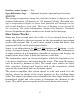
Fig. 1 Fig. 2 Fig. 3 Fig. 4 These figures show results of different sensitivity levels on the same location. Fig. 1: Sensitivity at 88 percent, determined by Auto Sensitivity. Typical of full auto mode. Fig. 2: Sensitivity set at 75 percent. Fig. 3: Sensitivity set at 50 percent. Fig. 4: Sensitivity set at 100 percent. You can change the sensitivity level whether you are in Auto Sensitivity mode or Manual Sensitivity mode.
Adjusting sensitivity in Auto Sensitivity Mode is similar to manually adjusting a car's speed with the accelerator pedal while cruise control is on. You can tell the car to run faster, but when you let off the gas the cruise control automatically keeps you from running slower than the minimum speed setting. In the unit, auto mode will let you increase sensitivity to 100 percent, but the unit will limit your minimum setting.
At left, Sonar Menu with Sensitivity command selected. At right, the Sensitivity Control Bar. NOTE: If you want to change the sensitivity in Manual Mode, first turn off Auto Sensitivity: from the Sonar Page, press MENU|↓ to AUTO SENSITIVITY|ENT|↑ to SENSITIVITY|ENT. Press ↓ or ↑ to pick a different sensitivity setting. When it's set at the desired level, press EXIT.
Fish Symbols vs. Full Sonar Chart You may have noticed in the quick reference that we used fish arches in full sonar chart mode for our example, and not the popular Fish I.D. fish symbol feature. Here's why. Fish I.D. is an easier way for a sonar novice to recognize a fishy signal return when he sees it. However, locating fish by symbol only has some limitations. Your sonar unit's microprocessor is remarkably powerful, but it can be fooled.
For the ultimate training aid, be sure to download the free emulator software for your unit. Aside from being just plain fun, this program can help you learn both basic and advanced operations without burning boat fuel! Eagle is one of the first sonar manufacturers to provide this type of training tool for customers. This PC application simulates the actual sonar unit on your computer. You can run it from your computer keyboard or use your mouse to press the virtual keys.
Notes 52
Section 4: Sonar Options & Other Features Material in this section is arranged in alphabetical order. ASP (Advanced Signal Processing) The ASP feature is a noise rejection system built into the sonar unit that constantly evaluates the effects of boat speed, water conditions and interference. This automatic feature gives you the best display possible under most conditions. The ASP feature is an effective tool in combating noise. In sonar terms, noise is any undesired signal.
At left, Sonar Menu with Sonar Features selected. In the Sonar Features menu, Noise Rejection is selected with ASP in the default low setting (center, dual-frequency menu; at right, single-frequency menu). To change the ASP level: 1. From the Sonar Page, press MENU|↓ to SONAR FEATURES|ENT. 2. Press ↓ to NOISE REJECTION|ENT. 3. Press ↓ or ↑ to select a setting, then press ENT. 4. To return to the previous page, press EXIT|EXIT. Alarms This unit has three different types of sonar alarms.
The last alarm is the Depth Alarm, which has both a Shallow and a Deep setting. This is useful as an anchor watch, a shallow water alert or for navigation. Depth Alarms The depth alarms sound a tone when the bottom signal goes shallower than the shallow alarm's setting or deeper than the deep alarm's setting. For example, if you set the shallow alarm to 10 feet, the alarm will sound a tone if the bottom signal is less than 10 feet. It will continue to sound until the bottom goes deeper than 10 feet.
2. Press ↑ or ↓ to change the first number, then press → to move the cursor to the next number and repeat until the depth is correct, then press ENT. 3. Press ← to SHALLOW ALARM ENABLED|ENT|EXIT. 4. To turn off the alarm, press ALARM|ENT|EXIT. To switch to a different depth setting, open the Sonar Alarms menu and repeat the instructions in step 3 above. To adjust and turn on the deep alarm: 1. Press ALARM|↓ to DEEP ALARM ENABLED|→ to DEEP ALARM DEPTH|ENT. 2.
At left, Sonar Alarms menu, with Adjust Zone command selected. At right, Adjust Zone Alarm selection box, with Upper selected. 4. Press EXIT|← to ZONE ALARM ENABLED|ENT|EXIT. Now, any echo — fish, bottom, structure — within the zone alarm's depth range will trigger the zone alarm. 5. To turn off the alarm, press ALARM|↓ to ZONE ALARM ENABLED|ENT|EXIT. To switch to a different depth setting, open the Sonar Alarms menu and repeat the instructions in steps 3 and 4 above.
Sonar Alarms menu with Fish Alarm selected. The check box to the left is blank, indicating the alarm is turned off. To turn the fish alarm on: 1. Press ALARM|↓ to FISH ALARM|ENT|EXIT. 2. To turn off the alarm, press ALARM|↓ to FISH ALARM|ENT|EXIT. Backlight Level The unit defaults to the maximum backlight level. To adjust the display's backlight level: Press MENU|MENU|↓ to BACKLIGHT LEVEL|ENT. The BACKLIGHT LEVEL slider bar appears. Press ↑ or ↓ to move the bar.
The Backlight Level control bar appears automatically whenever you turn on the unit. Calibrate Speed The speed sensor can be calibrated to compensate for inaccuracies. Before you change the setting, first calculate the percentage that the speed is off. You will enter this percentage in a moment. For example, if you figure the sensor is reading 10 percent faster than actual speed, you will enter – 10 in the calibration window.
2. Enter the number you calculated earlier: press ↑ or ↓ to change the first character (+ or –), then press → to move the cursor to the next number and repeat until the percentage is correct, then press EXIT. Chart Speed The rate that echoes scroll across the screen is called the chart speed. The default is maximum; we recommend that you leave the speed set there for virtually all fishing conditions. However, you might consider experimenting with chart speed when you are stationary or drifting very slowly.
If you do experiment with chart speed, remember to reset it to maximum when you resume trolling or moving across the water at higher speed. To change chart speed: 1. From the Sonar Page, press MENU|↓ to CHART SPEED|ENT. 2. The Chart Speed Control Bar appears. Press ↓ to decrease chart speed; press ↑ to increase chart speed. 3. When it's set at the desired level, press EXIT. ColorLine ColorLine lets you distinguish between strong and weak echoes.
At left, Sonar Page menu with ColorLine command selected. At right, the ColorLine control bar. Wider ColorLine Thin or no ColorLine At left, little ColorLine indicates a soft bottom, probably sand or mud. At right, the wider ColorLine indicates a harder, rocky bottom.
Contrast To adjust the display's contrast: Press MENU|MENU|ENT. The CONTRAST slider bar appears. Press ↑ or ↓ to move the bar. The lower end of the scale is minimum contrast; the upper end is maximum contrast. Depth Cursor The depth cursor consists of a horizontal line with a digital depth box on the right side. The numbers inside the box show the depth of the cursor. Cursor line Depth box At left, Sonar Page menu with Depth Cursor command selected. At right, sonar chart with the depth cursor active.
Depth Range - Automatic When turned on for the first time, the bottom signal is automatically placed in the lower half of the screen. This is called Auto Ranging and is part of the automatic function. However, depending upon the bottom depth and the current range, you can change the range to a different depth. To do this: 1. From the Sonar Page, press MENU|↓ to DEPTH RANGE|ENT. At left, Sonar Page menu with Depth Range command selected. At right, the Depth Range Control Scale. 2.
To switch to Manual Depth Range: 1. First, turn off automatic depth range. From the Sonar Page, press MENU|↓ to AUTO DEPTH RANGE|ENT. 2. Press ↑ to DEPTH RANGE|ENT and the Depth Range Control Scale appears. 3. Press ↓ or ↑ to select a different depth range. A horizontal black bar highlights the selected range. 4. When the new range is selected, press EXIT to clear the menu. To turn Auto Depth Range on again: From the Sonar Page, press MENU|↓ to AUTO DEPTH RANGE|ENT|EXIT.
Surface clutter Fish arches Structure In FasTrack, fish arches show as horizontal bars. Bottom signal ColorLine Sonar Page showing FasTrack. FasTrack bar graph Fish I.D. (Fish Symbols & Depths) The Fish I.D. feature identifies targets that meet certain conditions as fish. The microcomputer analyzes all echoes and eliminates surface clutter, thermoclines, and other signals that are undesirable. In most instances, remaining targets are fish. The Fish I.D.
Does that mean Fish I.D. is broken? No — the feature is simply interpreting sonar returns in a specific way to help take some of the work out of reading the screen. Remember: Fish I.D. is one of the many tools we provide so you can analyze your sonar returns for maximum fish finding information. This and other features can help you successfully "see" beneath the boat under varied water and fishing conditions. So, practice with the unit in both the Fish I.D.
To turn on FishTrack: (Note: These instructions will turn on FishTrack and Fish I.D. at the same time.) 1. From the Sonar Page, press MENU|↓ to SONAR FEATURES|ENT. 2. Press ↓ to DEPTHS|ENT|EXIT|EXIT. To turn off FishTrack, repeat the instructions in step 1. Turning off FishTrack in this manner will not turn off Fish I.D. symbols. Symbols with FishTrack depths Sonar Features menu with Fish I.D. Depths selected (at left, dualfrequency menu; center, single-frequency menu).
The default frequency is 200 kHz, which is best for use in shallow water (about 300 feet or less). This frequency is the best choice for about 80 percent of the fresh and salt water sport fishing applications. When you get into very deep salt water, 300 to 500 feet or deeper, the 50 kHz frequency is the best choice. The 200 kHz transducer will give you better detail and definition, but less depth penetration.
3. Press EXIT|EXIT to clear the menu. To change the frequency setting to 200 kHz: 1. From the Sonar Page, press MENU|↓ to SONAR FEATURES|ENT. 2. Press ↓ to FISH SYMBOLS|→ to 200 KHZ|ENT. 3. Press EXIT|EXIT to clear the menu. HyperScroll See the entry on Ping Speed, which controls the HyperScroll feature. Noise Rejection See the entry on Advanced Signal Processing in this section. Overlay Data To change the digital data shown "floating" on top of the Sonar Page: To select data for display: 1.
Overlay Data command on the Sonar Menu, at left. Overlay Data Shown selection menu, right. In this example, Depth will be displayed in a large font. When selected, the data type shifts to the top of the data list and a check mark appears beside the data type. (If you wish, you may now use ↓ or ↑ to select other Data Types for display.
Data list showing Water Speed selected to display on Sonar Page. 3. To return to the previous page, press EXIT. To turn off displayed data: 1. Press MENU|↓ to OVERLAY DATA|ENT. 2. Press ↓ or ↑ to select Data Type|ENT. The selected data type disappears from the top of the list and reverts to its previous, unchecked position. (If you wish, you may now use ↓ or ↑ to select other Data Types to turn off.) 3. To return to the previous page, press EXIT. To change displayed data font size: 1.
Tip: If you wish, you can change the displayed data font size when you select a data type: 1. From the Sonar page, press MENU|↓ to OVERLAY DATA|ENT. 2. Press ↓ or ↑ to select Data Type|press → or ← to select Data Size|ENT. The data will be shown in the new font size. To return to the previous page, press EXIT. Sonar Page with Overlay Data turned on. This example shows Depth, Water Temperature and Water Speed. NOTE: Some data types can be displayed in only one font size.
matically provides enough return echoes to refresh the screen and scroll the chart at maximum chart speed. However, when you are running at high speeds, or just want the fastest possible screen update, you may want to use the HyperScroll feature. When you change the Ping Speed to any setting greater than 50 percent, the unit automatically enters HyperScroll mode.
To change Ping Speed: 1. From the Sonar Page, press MENU|↓ to PING SPEED|ENT. 2. The Ping Speed Control Bar appears. Press ↑ to increase ping speed; press ↓ to decrease speed. When it's set at the desired level, press EXIT. To adjust Sensitivity: 1. From the Sonar Page, press MENU|ENT. 2. The Sensitivity Control Bar appears. Press ↓ to decrease sensitivity; press ↑ to increase sensitivity. When it's set at the desired level, press EXIT. (When you reach the maximum or minimum limit, a tone sounds.
Example showing the Pop-up Help message for the Sensitivity command, located on the Sonar Menu. Reset Options This command is used to reset all features, options and settings to their original factory defaults. This is useful when you have changed several settings and want to return the unit to basic automatic operation. 1. Press MENU|MENU|↓ to RESET OPTIONS|ENT. 2. Press ← to YES|ENT. 3.
At left, Main Menu with Reset Options command selected. At right, the Reset Options dialog box, with "Yes" selected. Reset Water Distance The sonar chart's Digital Data display option includes a box that shows distance traveled, called Water Distance. This information is calculated from an optional water speed sensor. The Water Distance window can be reset to zero using the Reset Water Distance command. Press MENU|MENU|↓ to RESET WATER DISTANCE|ENT.
surface, and the screen shows the water depth as 30 feet, then the actual depth is 31 feet. On sailboats or other large vessels with deep drafts, the distance between the transducer installation and the keel or lower engine unit can be several feet. In those cases, an inexact depth reading could result in grounding or striking underwater structure. The Keel Offset feature eliminates the need for the navigator to mentally calculate how much water is under his keel.
2. The Keel Offset dialog box appears with a plus (+) sign at the front of the box. 3. Press → to the first number, then press ↑ to change the number to 1. 4. Press → to the second number, them press ↑ to change the number to 5, then press EXIT. The depth indicators now accurately show the water depth from surface to bottom. Sensitivity & Auto Sensitivity The sensitivity controls the ability of the unit to pick up echoes. Sensitivity can be adjusted, because water conditions vary greatly.
can adjust sensitivity up to 100 percent but the unit will limit your minimum setting. In auto, the unit will continue to make small adjustments, allowing for the setting you selected. In manual mode, you have complete control over sensitivity, with the ability to set it anywhere from zero to 100 percent. Once you select a level in manual, the unit will continue to use that exact sensitivity setting until you change it or revert to auto mode. To adjust sensitivity in auto mode: 1. Press MENU|ENT. 2.
To adjust sensitivity in manual mode: 1. First, turn off Auto Sensitivity: from the Sonar Page, press MENU|↓ to AUTO SENSITIVITY|ENT. 2. Press ↑ to SENSITIVITY|ENT and the Sensitivity Control Bar appears. Press ↓ or ↑ to pick a different sensitivity setting. When it's set at the desired level, press EXIT. To turn Auto Sensitivity back on: From the Sonar Page, press MENU|↓ to AUTO SENSITIVITY|ENT|EXIT.
1. Press MENU|MENU|↓ to SOFTWARE INFO|ENT. 2. Read the information displayed on the screen. 3. To return to the last page displayed, press EXIT|EXIT. Sonar Chart Mode The default color scheme for the sonar chart is white background, but we offer other variations to suit your viewing preferences. You can select the chart to be displayed in grayscale, reverse grayscale, blue background, Nightview, IceView, or bottom color tracking. To change the chart mode color scheme: 1.
Full Sonar Chart This is the default mode used when the unit is turned on for the first time or when it's reset to the factory defaults. The bottom signal scrolls across the screen from right to left. Depth scales on the right side of the screen aid in determining the depth of targets. The line at the top of the screen represents the surface. The bottom depth and surface temperature (if equipped with a temperature sensor or a transducer with a temp sensor built in) show at the top left corner of the screen.
Split Zoom Sonar Chart A split chart shows the underwater world from the surface to the bottom on the right side of the screen. The left side shows an enlarged version of the right side. The zoom range shows at the bottom left corner of the screen. Split Zoom Sonar Chart. Image at left shows the left window zoomed to 2X. The right image shows the left window zoomed to 4X. Digital Data/Chart This mode shows the chart on the right side of the screen.
Digital Data/Chart Customizing the Digital Data/Chart Screen The Digital Data/Chart screen can be customized to show digital data different from the defaults first shown. To customize this screen: 1. From the Sonar Page (in Digital Data mode), press MENU|↓ to CUSTOMIZE|ENT. At left, the Sonar Menu showing the Customize command highlighted. At right, the Water Temperature box is selected.
2. The Water Temperature box title bar flashes, indicating the box contents can be changed. Press ENT|↑ or ↓ to select data type|ENT|EXIT. Water Distance has been picked to replace Water Temperature in the top digital data box. Tip: You can customize other digital data boxes before returning to the Sonar Page. After changing the first box by selecting the Data Type and pressing Enter, use the ↓ key to select another box to change.
Main Menu with Sonar Simulator command selected. The Simulator is turned off (check box is unchecked). NOTE: If you turn on your unit before attaching a transducer, it may enter a demo mode. The words "demo mode" flash on the bottom of the screen and a sonar chart plays much like the simulator. Unlike the simulator, the demo mode is for demonstration only, and will automatically stop as soon as you turn on the unit with a transducer attached. The simulator will continue to function normally.
Sonar Menu with Stop Chart command selected. The box is unchecked, indicating that the chart is scrolling across the screen. Surface Clarity The markings extending downward from the zero line on the chart are called "surface clutter." These markings are caused by wave action, boat wakes, temperature inversion and more. The surface clarity control reduces or eliminates surface clutter signals from the display.
Sonar Features menu with Surface Clarity selected (at left, dualfrequency menu; at right, single-frequency menu). 2. Press ↓ or ↑ to select clarity level|EXIT|EXIT. Surface clutter In the illustration at left, Surface Clarity is turned off. The right view shows Surface Clarity set at High.
Transparency Use the transparency menu to adjust the transparency of menu windows. A high transparency allows you to continue monitoring the sonar chart while adjusting feature settings, though the text of the menus may fade until it is unreadable. A low transparency will usually make menu text easier to read, at the cost of watching your sonar returns. Experiment with this feature until you find the right level of transparency for your eyes. Main Menu with Transparency command selected.
The Units of Measure Menu. To set Units of Measure: Press ↓ to the desired units, then press ENT. After all the options are set as desired, press EXIT|EXIT to return to the page display. Volume This command adjusts the speaker volume, which controls the sound levels for keystrokes and alarms. If you want to turn off all sounds, set the volume to zero. To adjust volume: 1. Press MENU|MENU|↓ to VOLUME|ENT. 2. The Volume Control Bar appears. Press ↓ to decrease the volume; press ↑ to increase the volume.
Pressing ZIN once doubles the size (2X) of all echoes on the screen. Pressing it again quadruples the size of the echoes (4X). Press the Zoom Out key, ZOUT, to return the display to the normal mode. At left, Sonar Page, normal view. Center, same view zoomed to 2X. Right, same view zoomed to 4X Zoom Pan Your unit has the handy ability to quickly zoom in on any portion of the water column with just the touch of an arrow key.
Section 5: Troubleshooting If your unit is not working, or if you need technical help, please use the following troubleshooting section before contacting the factory customer service department. It may save you the trouble of returning your unit for repair. For contact information, refer to the last page, just inside the back cover of this manual. Unit won't turn on: 1. Check the power cable's connection at the unit. Also check the wiring. 2. Make certain the power cable is wired properly.
Weak bottom echo, digital readings erratic, or no fish signals: 1. Make sure the transducer is pointing straight down. Clean the face of the transducer. Oil, dirt and fuel can cause a film to form on the transducer, reducing its effectiveness. If the transducer is mounted inside the hull, be sure it is shooting through only one layer of fiberglass and that it is securely bonded to the hull.
2. Electrical noise from the boat's motor can interfere with the sonar. This causes the sonar to automatically increase its Discrimination or noise rejection feature. This can cause the unit to eliminate weaker signals such as fish or even structure from the display. Try using resistor spark plugs or routing the sonar unit's power and transducer cables away from other electrical wiring on the boat. No fish arches when the Fish I.D. feature is off: 1. Make certain the transducer is pointing straight down.
tivity should be set at 90-95 percent. There should be a steady bottom signal on the display. Now turn on each piece of electrical equipment on the boat and view the effect on the sonar's display. For example, turn on the bilge pump and view the sonar display for noise. If no noise is present, turn the pump off, then turn on the VHF radio and transmit. Keep doing this until all electrical equipment has been turned on, their effect on the sonar display noted, then turned off.
Section 6: Supplemental Material FCC Compliance This device complies with Part 15 of the U.S. Federal Communications Commission (FCC) Rules. Operation is subject to the following two conditions: (1) this device may not cause harmful interference, and (2) this device must accept any interference received, including interference that may cause undesired operation. Changes or modifications not expressly approved by the manufacturer could void the user's authority to operate the equipment.
Notes 98
Index Manual, 64 Display Options, 38, 49, 82, 83, 84, 85 F FasTrack, 65 Fish Depths, 67 Fish I.D., 50, 54, 57, 66 Fish Symbols, 50, 54, 57, 66, 70; Interpreting, 50 FishTrack, 67 Frequency, 3, 68; Change Frequency, 68 G Grayline, 79 H HyperScroll, 70, 73, 74 I Icons, 5 Information Displays (Customize Display), 84, 86 Installation, 7, 24, 27, 31, 32, 33, 34, 35; Sec. 2, Installation & Accessories, 7 Introduction: Sec.
S Sensitivity, 23, 45, 46, 47, 48, 49, 75, 76, 79, 80, 81, 96 Simulator, 40, 86, 87 Software Version Information, 81 Sonar Chart Color Mode, 82 Sonar Chart Display Options, 38, 49, 82, 83, 84, 85 Sonar Menu, 49, 54, 71, 74, 76, 80, 85, 88 Sonar Operation: Quick Reference, 45 Speaker, 91 Speed Sensors, 4, 26, 27, 28, 29, 59, 77, 84 Stop Chart, 87, 88 Surface Clarity, 88, 89 T Temperature Sensors, 8, 12, 26, 27, 83 Text Boxes (Customize Display), 84, 86 Transducer, 1, 3, 4, 7, 8, 9, 10, 11, 12, 13, 14, 15, 16
U Units of Measure, 40, 90, 91 Utilities, 37 Z Zooming, 3, 38, 45, 83, 91, 92, 95; Zoom Bar, 91; Zoom Pan, 92 101
Notes 102
EAGLE ELECTRONICS FULL ONE-YEAR WARRANTY "We," "our," or "us" refers to EAGLE ELECTRONICS, a division of LEI, the manufacturer of this product. "You" or "your" refers to the first person who purchases this product as a consumer item for personal, family, or household use. We warrant this product against defects or malfunctions in materials and workmanship, and against failure to conform to this product's written specifications, all for one (1) year from the date of original purchase by you.
How to Obtain Service… …in the USA: We back your investment in quality products with quick, expert service and genuine Eagle replacement parts. If you're in the United States and you have technical, return or repair questions, please contact the Factory Customer Service Department. Before any product can be returned, you must call customer service to determine if a return is necessary. Many times, customer service can resolve your problem over the phone without sending your product to the factory.
Accessory Ordering Information for all countries To order Eagle accessories such as power cables or transducers, please contact: 1) Your local marine dealer or consumer electronics store. Most quality dealers that handle marine electronic equipment or other consumer electronics should be able to assist you with these items. To locate an Eagle dealer near you, visit our web site, and look for the Dealer Locator (www.eaglesonar.com/Products/HowToBuy/dealers.asp).
Visit our web site: www.eaglesonar.com Eagle Pub.