Pub. 988-0143-881 www.eaglesonar.com Mapping GPS Receiver Installation and Operation Instructions www.Busse-Yachtshop.de email: info@busse-yachtshop.
Copyright © 2005 LEI-Eagle. All rights reserved. No part of this manual may be copied, reproduced, republished, transmitted or distributed for any purpose, without prior written consent of Eagle Electronics. Any unauthorized commercial distribution of this manual is strictly prohibited. Eagle and IntelliMap are registered trademarks of LEI. MapCreate, FreedomMaps and NauticPath are trademarks of LEI. Fishing Hot Spots is a registered trademark of Fishing Hot Spots Inc.
Table of Contents Section 1: Read Me First!............................................................... 1 Capabilities and Specifications: IntelliMap® 640c ............................ 2 How GPS Works ................................................................................. 4 Introduction to GPS and WAAS......................................................... 6 How to use this manual: typographical conventions ........................ 8 Arrow Keys ................................................
Navigate to a Point of Interest......................................................... 46 Creating and Saving a Trail............................................................. 46 To Save a Trail .............................................................................. 47 Displaying a Saved Trail .................................................................. 48 To turn off trail display:................................................................ 48 To turn on trail display:................
Waypoint Position ......................................................................... 66 Selecting a Waypoint .................................................................... 66 Set a Waypoint by Average Position ............................................ 66 Set a Waypoint by Projecting a Position...................................... 67 Section 5: System & GPS Setup Options .................................. 69 Alarms .............................................................................
Screen Contrast and Brightness ...................................................... 93 Set Language .................................................................................... 93 Set Local Time .................................................................................. 93 Show WAAS Alarm........................................................................... 94 Software Version Information.......................................................... 94 Sounds and Alarm Sound Styles........
Section 1: Read Me First! How this manual can get you out on the road, fast! Welcome to the exciting world of digital GPS! We know you're anxious to begin navigating, but we have a favor to ask. Before you grab the IntelliMap® 640c and begin installing it, please give us a moment or two to explain how our manual can help you get the best performance from your compact, wide-screen, mapping GPS receiver. First, we want to thank you for buying an Eagle GPS unit.
After you've learned the basics (or if you already have some GPS experience), you may want to try out some of the IntelliMap 640c's many advanced navigation features. That brings us to Section 4, Advanced GPS Operations. This section contains the rest of the unit's GPS command functions, organized in alphabetical order.
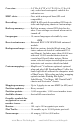
Case size:......................... 5.4" H x 6.9" W x 3.4" D (13.8 x 17.6 x 8.6 cm); sealed and waterproof; suitable for saltwater use. MMC slots: ...................... One, with waterproof door (SD card compatible). Recording:........................ MMC & SD cards for recording GPS trip details and displaying charts or custom maps. Back-up memory: .......... Built-in memory stores GPS data for decades. User settings are stored when unit is turned off. Languages:......................
NOTE: The above memory capacities refer only to the IntelliMap 640c's onboard memory. The amount of GPS data you can record and save for recall later is limited only by the number and size of MMC cards you have. NOTICE! The storage temperature range for your IntelliMap 640c is from -4 degrees to +167 degrees Fahrenheit (-20 degrees to +75 degrees Celsius). Extended storage in temperatures higher or lower than specified will damage the liquid crystal display in your unit.
The background map is suitable for many navigation chores, but for maximum accuracy and much more detail, you need our optional mapmaking software, MapCreate 6, or one of our special plug-and-play mapping cards. Some unit features — such as searching for businesses and addresses — won't work without a custom MapCreate map. There is so much detail in our background map and even more in MapCreate that we'll describe their contents and differences in Section 3, Basic GPS Operations, on page 36.
Introduction to GPS and WAAS Well, now you know the basics of how the unit does its work. You might be ready to jump ahead to Section 2, Installation & Accessories, on page 11, so you can mount your IntelliMap 640c and plug in the power. Or you might want to see how our text formatting makes the manual tutorials easy to skim. If that's the case, move on to "How to Use This Manual" on page 8.
The system requires signal reception from three satellites in order to determine a position. This is called a 2D fix. It takes four satellites to determine both position and elevation (your height above sea level — also called altitude). This is called a 3D fix. Remember, the unit must have a clear view of the satellites in order to receive their signals. Unlike radio or television signals, GPS works at very high frequencies.
only a tool. Always have another method of navigation available, such as a map or chart and a compass. Also remember that this unit will always show navigation information in the shortest line from your present position to a waypoint, regardless of terrain! It only calculates position, it can’t know what’s between you and your destination, for example. It’s up to you to safely navigate around obstacles, no matter how you’re using this product.
4. The wait message disappears and the IntelliMap 640c begins showing navigation information along the trail. Now, begin moving and follow your IntelliMap 640c. Translated into complete English, step 1 above would mean: "Start on the Map Page. Press the Menu key twice. Next, repeatedly press (or press and hold) the down arrow key to scroll down the menu and select (highlight) the My Trails menu command. Finally, press the Enter key.
Notes 10 www.Busse-Yachtshop.de email: info@busse-yachtshop.
Section 2: Installation & Accessories Preparations You can install the GPS system in some other order if you prefer, but we recommend this installation sequence: Caution: You should read over this entire installation section before drilling any holes in your vehicle or vessel! 1. Determine the approximate location for the GPS unit, so you can plan how and where to route the cables for the antenna and power. This will help you make sure you have enough cable length for the desired configuration. 2.
You need to select an antenna installation location that has a clear, unobstructed view of the sky. After the module is installed, route the cable to the unit, plug it in the center socket on the back and your system is ready to use. See the module's instruction sheet, publication part number 988-0148-371, for complete installation directions. In an automobile, you may achieve good results by placing the external antenna on the top of the dash or at the base of the windshield.
For example, if you have to extend the power cable to the battery or power buss, attach one end of the fuse holder directly to the battery or power buss. This will protect both the unit and the power cable in the event of a short. It uses a 3-amp fuse. To unit Optional power off switch for saltwater installations Red wire with 3 amp fuse Black wire 12 volt battery Power connections for the IntelliMap 640c GPS unit.
Rear view of unit Power Connector GPS Connector NMEA 0183 Com Port Power cable 3-amp fuse Com port data wires (three) GPS antenna module 12-volt battery Cable connections. NMEA Cable Connections NMEA is a standard communications format for marine electronic equipment. For example, an autopilot can connect to the NMEA interface on the IntelliMap 640c and receive positioning information. The IntelliMap 640c can exchange information with any device that transmits or receives NMEA 0183 data. 14 www.
However, a communications cable is not available for the unit at this time. If you need to create a NMEA 0183 connection consult customer service. Service contact information can be found in the back of this manual. NMEA Wiring To exchange NMEA data, the IntelliMap 640c has one NMEA 0183 version 2.0 communication port. Com port one (Com-1) can be used to receive NMEA format GPS data. The com port can also transmit NMEA format GPS data to another device. A data cable should contain three wires.
Optional R-A-M mounting system. Bracket Installation Mount the IntelliMap 640c in any convenient location, provided there is clearance behind the unit when it's tilted for the best viewing angle. You should also make sure there is enough room behind the IntelliMap 640c to attach the power and GPS antenna/receiver module cables. A drawing on the next page shows the dimensions of a gimbal-mounted IntelliMap 640c. Holes in the bracket's base allow wood screw or through-bolt mounting.
72.9 [2.87] 23.4 [0.92] 173.9 [6.85] 137.9 [5.43] 157.9 [6.22] 56.9 [2.24] Millimeter [Inch] Front view (left) and side view (right) showing dimensions of the IntelliMap 640c when mounted on gimbal bracket. After drilling the hole, pass the antenna connector up through the hole from under the dash. Pass the power cable's bare-wire end down though the hole from the top. If you wish, you can fill in the hole around the cables with a good marine sealant compound.
146.5 [5.76] Top R 7.9 [0.31] In-Dash Template 113.5 [4.46] Millimeters [Inches] ALWAYS VERIFY DIMENSIONS In-dash mounting template for the IntelliMap 640c, showing dimensions. NOTE: The figure above is not printed to scale. a scaled template (FM-5 In-Dash Adapter Kit instructions) is available for free download from our web site, www.eaglegps.com. Portable Installation Like many Eagle products, the IntelliMap 640c is capable of portable operation by using an optional portable power pack (PPP).
"D" cell battery Installing batteries in a typical portal power pack. MMC or SD Card Memory Card Installation Your IntelliMap 640c uses a MultiMedia Card to store information, such as custom maps, waypoints, trails and other GPS data. NOTE: Throughout this manual, we will use the term MMC, but just remember that your unit can use an MMC or SD card to store data. Both of these solid-state flash memory devices are about the size of a postage stamp. An SD card is slightly thicker than an MMC.
MMC groove for card removal Thumb screw Insert card face up, this way Memory card compartment with a 16 MB MMC card installed. To remove an MMC 1. Open the card compartment door by unscrewing the thumb screw. The screw should only be finger tight. If it was over-tightened, use a thumbnail, a coin or a screwdriver to open the door. 2. Just press a finger against the label of the MMC and drag it from the slot. 3. Close the compartment door and fasten the thumb screw finger tight.
MapCreate™ 6 CD-ROM (left) and MMC card reader for USB ports on the right. Now that you have your IntelliMap 640c installed, move on to Section 3, Basic GPS Operations. There, we'll present a series of step-by-step tutorials to teach you the basics of GPS navigation. 21 www.Busse-Yachtshop.de email: info@busse-yachtshop.
Notes 22 www.Busse-Yachtshop.de email: info@busse-yachtshop.
Section 3: Basic GPS Operations This section addresses the unit's most basic GPS operations. The tutorials presented in Sec. 3 follow a chronological order. Sec. 4, Advanced GPS Operations, will discuss other more advanced functions and utilities. Material in Sec. 4 is arranged in alphabetical order. Before you turn on the unit and find where you are, it's a good idea to learn about the different keys, the three Page screens and how they all work together.
3. MENU – Press this key to show the menus and submenus, which allow you to select a command or adjust a feature. This also accesses search functions for streets, intersections, addresses and highway exits. 4. ARROW KEYS – These keys are used to navigate through the menus, make menu selections and move the map cursor. 5. ENT/ICONS (Enter & Icons) – This key allows you to save data, accept values or execute menu commands. It is also used to create event marker icons. 6.
Main Menu. The Main Menu commands and their functions are: Screen command: changes the contrast or brightness of the display screen. Sounds command: enables or disables the sounds for key strokes and alarms and sets the alarm style. Transparency command: adjust the level of transparency for menus. Alarms command: turns GPS alarms on or off and changes alarm thresholds. Route Planning command: used to plan, view or navigate a route. My Trails command: shows, hides, creates and deletes plot trails.
Pages The unit has three Page displays that represent the three major operating modes. They are the Satellite Status Page, the Navigation Page and Map Page. They are accessed by pressing the PAGES key, then using → or ← to select a Page. Exit the Pages Menu by pressing EXIT. Pages Menu showing Map display options. Satellite Status Page The Satellite Status Page, shown in the following images, provides detailed information on the status of the unit's satellite lock-on and position acquisition.
Satellite Status Page. The first figure (left) indicates unit has not locked on to any satellites and does not have a fix on its position. The second figure (right) shows satellite lock-on with a 3D position acquired (latitude, longitude and altitude), and WAAS reception. This screen shows a graphical view of the satellites that are in view. Each satellite is shown on the circular chart relative to your position. The point in the center of the chart is directly overhead.
The Satellite Status Page has its own menu, which is used for setting various options. Options and setup are discussed in Sec. 5. To access the Satellite Status Page Menu, from the Status Page, press MENU. Navigation Page This screen has a compass rose that not only shows your direction of travel, but also the direction to a recalled waypoint. To get to the Navigation Page: Press PAGES|→ or ← to NAVIGATION|EXIT.
Speed is the velocity you are making over the ground. If you prefer, you can customize the Speed data box to display Closing Speed instead. Closing Speed is also known as velocity made good. It's the speed that you're making toward the waypoint. For instructions, see the Customize Page Displays entry in Sec. 5. Track is the heading, or the current direction you are actually traveling. Bearing is the direction of a line-of-sight from your present position to the destination.
steer left to return to the desired course. You can use the ZIN or ZOUT keys to change the cross track error range. Travel Time is the time that it will take to reach your destination at your present closing speed. You can also customize the time data box to show Arrival Time instead. Arrival Time is the local time it will be when you arrive at the destination, based upon your present closing speed and track.
Map Page opening screen (left). Map zoomed to 100 miles (center). Map zoomed to 10 miles (right). Over Zoomed, listed at the top of the map screen (right) means you have reached the detail limits in an area covered only by the basic background map. Zooming in any closer will reveal no more map details because a high-detail custom map has not been loaded on the MMC for this area. If you are using only the factory-loaded background map, the maximum zoom range for showing additional map detail is 15 miles.
Background map vs. MapCreate map content The background map includes low-detail maps of the whole world (containing cities, major lakes, major rivers, political boundaries) and medium-detail maps of the United States. The medium-detail U.S. maps contain: all incorporated cities; shaded metropolitan areas; county boundaries; shaded public lands (such as national forests and parks); some major city streets; Interstate, U.S.
Minor Streets Interstate Major Street Cursor line POI Pop-up POI Marker School POI Restaurant POI Position, distance and bearing data Zoom Range When the map is zoomed out far enough, most POIs appear as square dots (left). As you zoom in closer, the symbols become readable icons. In the 0.
Digital Data map page option. In pages that have two major windows you can toggle back and forth between the two windows by pressing PAGES|PAGES. This allows you to change the active map. Only when a map is active are you able to make adjustments to it. Pages Menu (left) with Two Map option selected. Map Page (right) with two map windows. Resize Window command Resize Window is another feature for pages that has two major windows.
the window widths. Press an arrow key parallel to the centerline to switch between horizontal and vertical layout. On the Map with Sonar page, you can only change size, not switch layout. It is always two vertical windows. Press EXIT to clear the four flashing arrows. Fig. 1. Fig. 3. Fig. 2. Fig. 4. (From left to right) Fig. 1. Resize Window command on the GPS Page menu. Fig. 2. Two Maps page display with four flashing arrows on the dividing centerline. Fig. 3.
Basic GPS Quick Reference Start outdoors, with a clear view of the open sky. As you practice, try navigating to a location at least a few blocks away. While you're learning, navigation in too small an area will constantly trigger arrival alarms. 1. Connect the unit to electric power and the antenna module. Make sure the MMC is in. (See complete installation details beginning on page 19.) 2. To turn on the unit, press and release PWR key. 3.
Find Your Current Position Finding your current position is as simple as turning the unit on. Under clear sky conditions, the unit automatically searches for satellites and calculates its position in approximately one minute or less. NOTE: "Clear sky" means open sky, unobstructed by terrain, dense foliage or structures. Clouds do not restrict GPS signal reception. If for some reason satellite acquisition takes longer, you may be inside a structure or vehicle or in terrain that is blocking signal reception.
Distance measured by cursor Pop-up name box Selected wreck Cursor line Cursor line The selected wreck (the Empress) to the southeast is 40 miles away. Selecting Any Map Item with the Cursor 1. Use the zoom keys and the arrow keys to move around the map and find the item you wish to select. 2. Use the arrow keys and center the cursor cross-hair on the desired object. On most items, a pop-up box will give the name of the selected item.
After the unit has acquired a position: 1. Press WPT|↓ to POI-RESTAURANTS. 2. You could search the entire restaurant category, but in this example we will narrow our search. Press → to FAST FOOD CHAINS|ENT|ENT. 3. The unit says it is calculating, then a list of restaurants appears, with the closest at the top of the list, and the farthest at the bottom of the list. The nearest is highlighted. Find Waypoint Menu (left). Category Selection menu (center). List of the nearest restaurants (right). 4.
5. The POI information screen appears. (This is how you can use this unit as a business phone directory!) If you wanted to navigate there, you could press Enter, since the Go To waypoint command is highlighted. But we just want to see it on the map, so press → to FIND ON MAP|ENT. 6. The unit's map appears, with the cross-hair cursor highlighting the restaurant' s POI symbol. A pop-up data box shows the POI's name.
You can create a waypoint at the cursor position on the map, or at your current position while you are navigating. You can create a waypoint at any location by manually entering the position's latitude and longitude. You can copy waypoints from your unit to your personal computer with MapCreate software. When you want to repeat a trip, these archived waypoints can be reloaded into your GPS unit.
Step 1. Step 2. Step 3. Step 4. Sequence for setting a waypoint. Step 1: while traveling, press WPT to call up Find Waypoint screen (seen in Step 2) and set a point. Step 3: a message says the waypoint has been saved. Step 4: vehicle continues on its way; number waypoint symbol is visible on map. Create Waypoint on Map 1. Use the arrow keys to move the cursor to the place where you want to make a waypoint. 2. Press WPT|WPT.
3. Press → to LATITUDE|ENT. Enter the latitude by pressing ↑ or ↓ to change the first character, then press → to the next character and repeat until the latitude is correct. Press ENT. 4. Press ↓ to LONGITUDE|ENT. Enter the longitude by pressing ↑ or ↓ to change the first character, then press → to the next character and repeat until the longitude is correct. Press ENT, then EXIT|EXIT to return to the previous page display.
Set Man Overboard (MOB) Waypoint One of boating's most terrifying events is having a friend or family member fall overboard. This unit has a man overboard feature that shows navigation data to the location where the feature was activated. To activate it, press the ZOUT and ZIN keys at the same time. Your position at the time these keys are pressed is used as the man overboard position. Caution: Saving a new Man Overboard waypoint will overwrite and erase the previous Man Overboard waypoint.
Navigate to Cursor Position on Map The GO TO CURSOR command navigates to the current cursor position on the map. It is a quick way to navigate to anything you can see on the map display. 1. Use the cursor with the zoom in and zoom out keys to move around the map until you find a location you want to go to. 2. Center the cursor over the location to select it. See the example in the following figure. Many map items such as waypoints, Points of Interest, towns, etc.
Active symbol Course Line The 60-mile zoom figure (left) shows the red course line connecting the current position to the destination. The Navigation Page (right) will also show navigation information. To stop navigating to the cursor, use the Cancel Navigation command. Press MENU|MENU|↓ to CANCEL NAVIGATION|ENT|← to YES|ENT. The unit stops showing navigation information.
until the length reaches the maximum trail point setting (default is 2,000, but the unit can record trails 9,999 points long). When the point limit is reached, the unit begins recording the trail over itself. With the default auto setting, this unit creates a trail by placing a dot (trail point) on the screen every time you change directions. The methods used for creating a trail and the trail update rate can both be adjusted or even turned off. See Sec. 5 for Trail Options.
Tip: Another quick way to stop recording one trail and begin a new one is to use the New Trail command. Press MENU|MENU|↓ to MY TRAILS|ENT|ENT. Caution: You also have the option of completely turning off trail recording, under the trail Options command. However, if the Update Active Trail option is left turned off, it will cancel the automatic trail creation feature. Displaying a Saved Trail The active trail is automatically displayed on the map with the factory default settings.
tween them is "navigating a trail" follows a trail forward (from start to end) while "backtracking" follows a trail in reverse (from end to start.) When hiking at walking speed with a hand-held GPS, we often just use visual back trailing because it is a bit better at following each little turn on a foot path. At faster speeds, such as the highway or on the water, the Navigate Trail and Backtrack Trail commands are handy. Visual Trailing 1. On the Map Page, zoom (ZIN or ZOUT) so your trail is visible. 2.
Figure 1. Figure 2. Figure 4. Figure 3. Navigate a trail menu sequence: Fig. 1, My Trails command. Fig. 2, Trails Menu. Fig. 3, Edit Trail Menu. Fig. 4, Edit Route Menu with Navigate Route command highlighted for Trail 2. A trail is always converted to a route when you navigate the trail. On the Map Page, the trail you are navigating is represented by a magenta line when the visible trail option is on. The course you are following is represented by a red line.
North Present position arrow Magenta trail line Trail point Navigate trail: Driver (left) is heading southeast straight toward trail point 3. Driver (right) has reached point 3 and has turned southwest to follow the trail.
NOTE: If you are already located at or near the end of your trail, the arrival alarm will go off as soon as you hit Enter. Just press EXIT to clear the alarm and proceed. 5. Now, begin moving and allow the unit to guide you. 6. When you reach your destination, be sure to cancel your navigation. Press MENU|MENU|↓ to CANCEL NAVIGATION|ENT. A confirmation message will appear. Press ←|ENT. Transfer Custom Maps and GPS Data Files Custom Maps: Custom maps work only from the MMC card or SD card.
Insert the MMC into your unit. Press MENU|MENU|↓ to SYSTEM SETUP|ENT|↓ to TRANSFER MY DATA|ENT. 2. The Transfer My Data menu includes a message which tells you if an MMC is present or not. If no MMC is present, you must first insert a card into the unit in order to activate the Load or Save commands. To transfer data from the unit to the MMC: press ENT (for SAVE.) To transfer data from the MMC to the unit: press → to LOAD|ENT. 3.
Figure 1. Figure 2. Figure 3. Figure 4. These figures show the menu sequence for loading a GPS Data File from an MMC into the unit's memory. Cancel Navigation You can turn off any of the navigation commands after you reach your destination or at any other time by using the Cancel Navigation command. Press MENU|MENU|↓ to CANCEL NAVIGATION|ENT|← to YES|ENT. 54 www.Busse-Yachtshop.de email: info@busse-yachtshop.
Section 4: Advanced GPS Operations Find Distance From Current Position To Another Location 1. While on the Map Page press MENU|↓ to FIND DISTANCE|ENT. 2. Center your cursor over the position you want to find the distance to. A rubber band line appears, connecting your current position to the cursor's location. The distance along that line will appear in a pop-up box. The box also shows the bearing to the point you're measuring to. 3. Press EXIT|EXIT to return to regular operation.
Icons Icons are graphic symbols used to mark some location, personal point of interest or event. They can be placed on the map screen, saved and recalled later for navigation purposes. These are sometimes referred to as event marker icons. This unit has 42 different symbols you can pick from when creating an icon. Icons are similar to waypoints, but they do not store as much information (like names) as waypoints do. You can't use a menu to navigate to icons as you can with waypoints.
Delete an Icon You can delete all the icons at one time, you can delete all icons represented by a particular symbol, or you can use the cursor to delete a selected icon from the map. Delete icons menu. 1. Press MENU|↓ to DELETE MY ICONS|ENT. 2. Press ↓ to DELETE ALL ICONS, DELETE BY SYMBOL or DELETE FROM MAP and press ENT. 3. The Delete All Icons confirmation message will appear. Press ← to YES|ENT. All icons will be deleted from the map. The Delete by Symbol command will launch the Select Symbol menu.
course of travel connecting waypoint to waypoint. The course from one waypoint to the next is a leg. Routes are composed of one or more legs. The legs of all GPS routes are based on straight lines between waypoints. A route allows you to navigate through several waypoints without having to reprogram the unit after arriving at each waypoint. Once programmed into the GPS unit, a route provides the option of navigating forward through the route waypoints or in reverse order.
2. Press ↑ to NEW ROUTE, then press ENT. To add to an existing route, press ↓ or ↑ to route name|ENT. Edit Route menu (left). Edit Route Waypoints menu (right) with Add From Map command selected. 3. Press ↓ to END OF ROUTE|ENT|↓ to ADD FROM MAP|ENT. The Map Page appears with the cursor showing. 4. Use the Zoom and arrow keys to move the map and cursor until the cursor is centered on the spot where you want your route to begin. 5. To set the first route waypoint press ENT.
4. 5. 6. Route creation sequence, continued: Fig. 4. Point (3) set at channel mouth. Fig. 5. Waypoint (4) set further south along the beach, at a recognizable landmark. The route will end with waypoint 5 at an oil platform. Fig. 6. Press EXIT to save the route and you return to this screen. 6. Move the cursor to the next point in the route, a spot where you need to turn or change direction, and press ENT to set the next waypoint. 7. Repeat step six until the route reaches your destination. 8.
Edit a Route Name 1. From the NAVIGATION PAGE, press MENU|ENT or from the MAP PAGE press MENU|MENU|↓ to ROUTE PLANNING|ENT. 2. Press ↓ to route name|ENT|→ to EDIT ROUTE NAME|ENT. 3. Press ↑ or ↓ to change the first character, then press → to move the cursor to the next character and repeat until the name is correct, then press ENT. Return to the previous page by pressing EXIT|EXIT|EXIT|EXIT. Edit Route Waypoints You can edit the route by adding and removing waypoints. 1.
Navigate a Route 1. From the NAVIGATION PAGE, press MENU|ENT or from the MAP PAGE, press MENU|MENU|↓ to ROUTE PLANNING|ENT. Route Planning command (left) on Main Menu. Routes menu (center) with Edit Route menu at right. Navigate Route command is selected. 2. Press ↓ to select saved route name|ENT. Highlight NAVIGATE and press ENT. 3. Upon arrival at your destination, cancel navigation. Press MENU|MENU|↓ to CANCEL NAVIGATION|ENT|← to YES|ENT.
Edit Route screen showing Route 1 with waypoints set to normal navigation (left). Reverse command has been executed (center) reversing the order of waypoints on the route. Pressing Navigate (right) will allow you to navigate the route from the end to the beginning. Trails Delete a Trail This is the command used to erase or delete a trail. Press MENU|MENU|↓ to MY TRAILS|ENT|↓ to trail name|ENT|→ to DELETE TRAIL|ENT|← to YES|ENT. To Delete all trails at once 1. Press MENU|MENU|↓ to MY TRAILS|ENT. 2.
Trail selected with map cursor (left). The box at the bottom of the screen shows distance and bearing from current position to the selected point on the trail. The Edit Trail menu (right). Edit a Trail Color To edit a trail color press MENU|MENU|↓ to MY TRAILS|ENT|↓ to trail name|ENT|↓ to COLOR|ENT. Press ↑ or ↓ to select a color style, then press ENT. Press EXIT repeatedly to return to the previous page.
Utilities Utilities are useful tools for traveling or for outdoor activities. Alarm Clock To get to the alarm clock menu press MENU|MENU|↓ to TIMERS|ENT|↓ to ALARM CLOCK|ENT. Sun/Moon Rise & Set Calculator To get to the Sun/Moon menu press MENU|MENU|↓ to SUN/MOON CALCULATIONS|ENT. Trip Calculator To get to the Calculator menu press MENU|MENU|↓ to TRIP CALCULATOR|ENT. Trip Down Timer To get to the Down Timer menu press MENU|MENU|↓ to TIMERS|ENT|↓ to DOWN TIMER|ENT.
highlighted in the list, press ENT|ENT to access waypoint information screen. 2. Use ↓ to select EDIT WAYPOINT, then press ENT|ENT. Press ↑ or ↓ to change the first character, then press → to the next character and repeat until the name is correct. Press ENT. To get back to the main page display, press EXIT repeatedly. Waypoint Symbol To edit waypoint symbol: 1. Press WPT|↑ to MY WAYPOINTS|ENT|↓ to name|ENT. Select waypoint from the list then press ENT|ENT. Use ↓ to select EDIT WAYPOINT.
4. The Edit Waypoint menu appears. Press EXIT repeatedly to get back to the main page display. Set a Waypoint by Projecting a Position This feature creates a waypoint at a location a specific distance and bearing from a reference position. The reference position can be a waypoint, map feature or Point of Interest. 1. Press WPT|↑ to MY WAYPOINTS|→ to NEW|ENT. 2. Press ↓ to PROJECTED POSITION|ENT|→ to CREATE|ENT. 3. Press CHOOSE REFERENCE|ENT.
Notes 68 www.Busse-Yachtshop.de email: info@busse-yachtshop.
Section 5: System & GPS Setup Options Alarms This unit has three GPS alarms: Arrival Alarm, Off Course Alarm and Anchor Alarm — the only one of the three set to Off by default. You can set an arrival alarm to flash a warning message and sound a tone when you cross a preset distance from a waypoint. For example, if you have the arrival alarm set to .1 mile, the alarm will flash a message when you come within .1 mile of your destination.
repeat until you are satisfied with the distance setting. If you want to enable the other alarms, repeat steps 2 and 3. 4. Press EXIT repeatedly to get back to the main page display. IMPORTANT ALARM NOTES: Anchor Alarm - The anchor alarm may be triggered even when you're sitting still. This typically happens when using small − less than .05 mile − anchor alarm ranges.
Menus for changing Com Port settings. For connectors and wiring information for another device, see page 15. For assistance in configuring the unit to communicate with another device, consult the factory. Customer service phone numbers are in the back of this manual. Also see the entry below for Configure NMEA. Configure NMEA You can configure the unit to use specific NMEA sentences. 1. Press MENU|MENU|↓ to SYSTEM SETUP|ENT. 2. Press ↓ to COMMUNICATIONS PORT|ENT|↓ to CONFIGURE NMEA 0183|ENT. 3.
• VLW transmits the distance traveled through water as measured by the paddle wheel. • VHW transmits the water speed as measured by the paddle wheel. 4. When the desired prefixes are checked or unchecked, press EXIT|EXIT|EXIT|EXIT to return to the previous page. Coordinate System Selection The Coordinate System Menu lets you select the coordinate system to use when displaying and entering position coordinates. Menus for changing coordinate system. To get to Coordinate System Selection: 1.
The Military Grid Reference System (MGRS) uses two grid lettering schemes, which are referred to as standard and standard + 10 MGRS on this unit. Your position and datum in use determines which one to use. If you use standard and your position is off significantly try the alternate. NOTE: When the position format is changed, it affects the way all positions are shown on all screens. This includes waypoints. To change the coordinate system, press ENT while COORDINATE SYSTEM is highlighted.
To configure a map fix: To use this format, you need to follow these steps in order. Take a map of the area and determine a reference latitude/longitude. NOTE: In order for this system to work, the latitude/longitude lines must be parallel with the edge of the map. USGS maps are parallel, others may not be. Also, this works better with smaller scale maps, such as 1:24000.
command SET AS ORIGIN selected. Press ENT and the unit returns to the Configure Map Fix menu. Finally, press EXIT to close this menu. Now press ↑ to COORD SYSTEM|ENT, select MAP FIX from the list and press ENT. Press EXIT repeatedly to get back to the main page display where all position information now is shown as a distance from the reference point you chose. Customize Page Displays The Satellite Status, Navigation, Map and Sonar pages all have customizable options.
GPS Simulator The GPS simulator simulates real world navigation. It is a great way to practice using your unit. You can set the starting location by entering latitude/longitude or from a stored waypoint, map place or POI location. You can steer the position arrow and change speed on the map by using the arrow keys — STEER WITH ARROWS command — or by setting the track and speed in the dialog boxes provided on the simulator menu screen. To get to the GPS Simulator: 1. Press MENU|MENU|↓ to GPS SETUP|ENT. 2.
mate TRACK (shown in compass degrees) that will point you toward the start of the trail/route. 2. Set SPEED to zero. Select STEER WITH ARROWS command and press ENT, which turns on the simulator and returns you to the Map Page. 3. Begin navigating along the trail/route. (If you are close enough to the first waypoint, the arrival alarm will usually go off as soon as navigation begins. Press EXIT to clear the alarm.) When navigation starts, press ↑ to increase speed to the desired setting. 4.
to the destination waypoint. As you travel toward the destination, the unit automatically zooms in — one zoom range at a time — keeping your current position and the destination on the screen. To turn this feature on from the MAP PAGE, press MENU|↓ to AUTO ZOOM|ENT|EXIT. Repeat these steps to turn it off. Map Data From the Map Data menu, you can turn off the map — which will turn the map into a GPS plotter — turn on or off pop-up map info boxes, draw map boundaries and fill water areas with white.
Fill Water With White From the Map Page, press MENU|↓ to MAP DATA|ENT. Press ↓ to FILL WATER WITH WHITE. With the option highlighted, press ENT to check it (turn on) and uncheck it (turn off.) After the option is set, press EXIT|EXIT to return to the page display. Map Overlays (Range Rings; Lat/Long Grid) The map screen can be customized with four range rings and/or grids that divide the map into equal segments of latitude and longitude. Range rings are handy for visually estimating distances on the map.
3. To return to the main page display, press EXIT|EXIT. A list of the datums used by this unit is in the back of this manual. GPS Setup Menu (left) Map Datum Menu at right. Map Detail Category Drawn This menu determines what mapping features are shown on the screen. This includes, waypoints, trails, icons, cities and highways, etc. You can turn on or off any of these items, customizing the map to your needs. To get to Map Categories Drawn: 1. From the Map Page, press MENU|↓ to MAP CATEGORIES DRAWN|ENT. 2.
Map Orientation By default, this receiver shows the map with north always at the top of the screen. This is the way most maps and charts are printed on paper. In Track Up mode, map shows "N" and arrow to indicate north. Map orientation shown in north up (left) and track up (right). This is fine if you are always traveling north. What you see to your left and right corresponds with the left and ride sides of the map. But if you travel any other direction, the map does not line up with your view.
Map Menu (left). Map Orientation menu with the North Up selected (right). NOTE: In North Up and Course Up, the present position arrow appears in the center of the map page. In Track Up, the position arrow appears centered in the lower third of the page. NauticPath USA Marine Charts Your unit can display NauticPath electronic charts on MMCs. They work just like a MapCreate custom map on a MMC.
To view Chart Note information: 1. Use the arrow keys to move the cursor over a Chart Note icon. When it's selected, a pop-up name box appears. 2. Press WPT to display the Note Information screen. 3. To scroll through the Chart Note screen, use ↑ ↓ arrow keys to read the information. To return to the main page display, press EXIT repeatedly. Entrance to Aransas Pass on a NauticPath chart with 8-nautical mile zoom (left).
Port Services icon Pop-up name box NauticPath chart showing Port Services icon selected by cursor. When first highlighted, the Pop-Up name box appears. Tidal Current Information NauticPath charts contain Tidal Current information, represented at large zoom ranges by a box icon with the letter "C." These icons will appear when you are zoomed in to a 6-mile range. The icon stands for a Tidal Current Station location. An example is displayed on the right.
Tidal Current Station icon in animated mode Cursor lines NauticPath chart showing Tidal Current Station icon selected by cursor (left). Icon animates automatically at .08-mile zoom range (right). Current Time Line Velocity Scale Slack Water Line Tide Tables Current Information screen. The Tidal Current Information screen displays daily tidal current data for this station on this date at the present time.
To select another date: 1. Use ← → to highlight month, day or year, then press ENT. 2. Use ↑ ↓ to select the desired month, day or year and press ENT. To clear the information screen, press EXIT. Tide Information NauticPath charts contain Tidal Information, represented at large zoom ranges by a box icon with the letter "T." These icons will appear when you are zoomed in to a 6-mile range. The icon stands for a Tidal Station location. An example is displayed at right.
Current Time Line Height Scale MLLW Line Tide Table Tide Information screen. The Tide Information screen displays daily tidal data for this station on this date at the present time. The graph at the top of the screen is an approximate view of the tidal range pattern for the day, from midnight (MN) to noon (NN) to midnight (MN). The dotted line across the graph is the Mean Lower Low Water line (MLLW).
2. From the Map Page, press MENU|↓ to MAP DATA|ENT|↓ to MAP CHOICE|ENT. Select the Map Name, then press ENT|EXIT|EXIT. South Chesapeake Navionics selected from Map Choice menu (right). WARNING: You should never format the MMC containing your Navionics chart. Formatting the MMC will permanently erase the chart from the card. Overlay Data On any Page display but Status you can float additional data of your own choosing in your display window.
Overlay Data, with "Navigation," "Trip Calculator" and "Time" categories expanded. To overlay information on your screen: 1. While on the Navigation Page or a Map Page, press MENU|↓ to OVERLAY DATA|ENT. 2. You'll see a list of the overlay data currently shown, if any. Select TO ADD) and press ENT. The data viewer shows information categories with "+" or "–" symbols next to each category name. A category with a "+" next to it is expandable, meaning its contents are currently hidden.
From Overlay Data Shown (left) press ENT to see Data Viewer (center). Select a category and press ENT; then select information to float on screen and press ENT (right). To remove overlaid data: 1. While on the Page that shows the item or items you want to remove, press MENU|↓ to OVERLAY DATA|ENT. 2. You'll see a list of the overlay data currently displayed. Select the item you want to remove from your display and press ENT|ENT to remove the data. To remove another item, select the item and press ENT|ENT.
1. From one of the Map Pages, press MENU|↓ to OVERLAY DATA|ENT. 2. You'll see a list of the overlay data currently displayed. Select the item you want to move and press ENT|→ to MOVE|ENT. 3. The data begins to flash on your screen. Use any combination of →, ←, ↑ and ↓ to move the data to a new location on the screen. 4. When satisfied, press EXIT|EXIT. NOTE: The Customize command and the Overlay Data command both use the same information categories.
Reset Options To reset all features to their factory defaults: 1. Press MENU|MENU|↓ to SYSTEM SETUP|ENT|↓ to RESET OPTIONS|ENT|← to YES|ENT. NOTE: Reset Options does not erase any waypoints, routes, icons or plot trails. System Menu with Reset Options command selected. Require WAAS You can choose to have WAAS signals automatically factored into every position reading. The default setting, Off, uses WAAS automatically, but does not require it to yield a position. To Require WAAS: 1.
Screen Contrast and Brightness To access the Screen menu, press MENU|MENU|ENT. The CONTRAST slider bar is already selected. Press ← → to adjust the contrast. To adjust the display's brightness: Press ↓ to BRIGHTNESS. Use ← → to adjust the brightness of the display. Screen Command (left). Screen menu with Contrast selected (center). Normal highlighted on Display Mode menu (right). To adjust the screen's display mode: Press ↓ to DISPLAY MODE|ENT. Press ↑ ↓ to select mode|EXIT.
To set the Month: Press ↓ to MONTH|ENT. Use ↑ ↓ to select the month and press ENT. To set the Day: Press ↓ → to DAY|ENT. Press ↑ ↓ to select the day and press ENT. To set the Year: Press ↓ → to YEAR|ENT. Press ↑ ↓ to select the year and press ENT. To set Time Format: Press ↓ to TIME FORMAT, highlight an option and press ENT to turn it on or off. To set Date Format: Press ↓ → to DATE FORMAT, highlight an option and press ENT to turn it on or off. The last field in this menu is CONFIG DST.
Main Menu (left) with Software Information command selected. The Software Information screen is shown at right. 1. Press MENU|MENU|↓ INFORMATION|ENT. to SYSTEM SETUP|ENT|↓ to SOFTWARE 2. Read the information displayed on the screen. 3. To return to the last page displayed, press EXIT|EXIT|EXIT. Sounds and Alarm Sound Styles Sounds triggered by key strokes and alarms can be adjusted: You first press MENU|MENU|↓ to SOUNDS|ENT. Sounds command, left. At right, the Sounds menu.
To set Alarm Sounds: Press ↓ to ALARM SOUNDS. With the option highlighted, press ENT to check it (turn on) and uncheck it (turn off.) After the option is set, press EXIT|EXIT to return to the page display. To set Alarm Volume: Press ↓ to VOLUME. Press → or ← to move the bar. The left end of the scale is low volume; the right end is high volume. After the option is set, press EXIT|EXIT to return to the page display. To set Alarm Style: Press ↓ to ALARM STYLE|ENT.
Main Menu (left). Trails Menu (center). Trail Options (right). Delete All Trails From the Trails Menu, press → to DELETE ALL|ENT|← to YES|ENT. Update Trail Option This menu lets you change the way the trail updates occur. From the Trails Menu, press → to TRAIL OPTIONS|ENT. With UPDATE ACTIVE TRAIL highlighted, press ENT to turn it on (check) or turn it off (uncheck). WARNING: If you uncheck the Update Trail option, automatic trail creation and recording will be turned off.
Update Rate setting (left) and Update Distance setting (right). Trail Name highlighted (left). Edit Trail menu (center). Trails menu with New Trail highlighted (right). Specific Trail Options Delete Trail From the Trails Menu, press ↓ to trail name|ENT. The Edit Trail menu appears. Press → to DELETE TRAIL|ENT|← to YES|ENT. New Trail To manually start a new trail, in the Trails Menu, highlight NEW TRAIL is highlighted and press ENT.
Transparency set to 0 percent (left), 50 percent (center) and 100 percent (right). Transparency Use the transparency menu to adjust the transparency of menu windows. A high transparency setting allows you to continue monitoring the screen's display while working with a menu. A low transparency usually will make menu text easier to read, at the cost of watching your display. To adjust Transparency level: Press MENU|MENU|↓ to TRANSPARENCY|ENT. The TRANSPARENCY slider bar appears.
Units of Measure This menu sets the speed, distance, depth, temperature and heading units. To change the units: Press MENU|MENU|↓ to SYSTEM SETUP|ENT|ENT. To set Units of Measure: Select a category you would like to change. Highlight the desired unit of measure option under the category and press ENT. Repeat those steps for each category that has a unit of measure option you would like to change. After all options are set, press EXIT repeatedly to return to the main page display.
Section 6: Searching NOTE: The background map loaded in your unit lets you to search for U.S. Interstate Highway exits and exit services, as well as some land features, including cities and lakes. For a full set of searchable land features, including landmarks, streets, addresses and Points of Interest, you must load your own high-detail custom map produced with our MapCreate 6 software. For a complete description of what detail is found in the background map and custom MapCreate maps, see page 32.
In search results, the distance and bearing to the selected item will be calculated from the current position. In the case of a cursor search, the search results show distance and bearing from the cursor, but an individual waypoint's information screen shows distance and bearing from the current (or last known) position. Find Addresses 1. From the Map Page, press MENU|↓ to FIND ADDRESS|ENT. 2. Press ENT to search in the Address field. 3.
is correct, then press ENT|ENT. B. Jump down to the lower selection list by pressing ENT, then press ↓ or ↑ to select a city name from the list, then press ENT. The city name you selected is now in the city field. NOTE: We recommend that you do not enter a city name unless the list you are given is too large when searching without it. This unit can actually search quicker without a city listed save time by not entering a city name.
Find Any Item Selected by Map Cursor On the Map Page, with a POI or map feature selected by the cursor press WPT. To return to the previous page, press EXIT. Map Page (left) showing location of the address on the map, highlighted by cursor. The address (right) is a business in the POI database, so you can display the POI information window, then navigate to it.
2. First, select a highway name by pressing ENT, which calls up the Find By Name menu. There are two highway search options. First, you can spell out the highway name in the top selection box. Press ↑ or ↓ to change the first letter, then press → to move the cursor to the next letter and repeat until the name is correct, then press ENT|ENT. Or you can jump down to the lower selection list by pressing ENT, then press ↓ or ↑ to select a highway from the list, then press ENT. Find By Name menu. 3.
4. In the Exit Information screen you have two choices. Press ENT to navigate or "go to" the exit or press →|ENT to find the exit on the map. "Go To Exit" option (left) and "Find On Map" option at right. Tip: You can also look up additional information on the Exit Services located near this exit. Press ↓ to SERVICES|press ↓ or ↑ to select Service Name|ENT. Exit Information screen (left) general location and amenities information at right. Find Map Places or Points of Interest (POI) 1.
Find Waypoint menu with Lodging POI category selected. 2. To search by nearest POI select NEAREST and press ENT. The Find BY menu will show a "calculating" screen, then a list of the nearest POI's will appear. Press ↓ or ↑ to the selected POI and press ENT to call up the POI's Waypoint Information screen. Find Waypoint menu (left) with category POI-Lodging and subcategory for Bed & Breakfast highlighted. Find By screen (center) and calculated results for Find By Nearest results shown at right. 3.
A list of Find by Nearest (left) and Waypoint Information menu at right. 4. When the POI's Waypoint Information screen is displayed, you can choose "Go To Waypoint" or "Find On Map" by pressing ↓ or ↑ |ENT. Find Streets or Intersections Find a Street 1. From the Map Page, press MENU|↓ to FIND STREETS|ENT and the Find Streets Menu appears. Find Streets command (left) with Find Streets menu at right. 2. You must first fill in a street name in the First Street dialog box.
to change the first letter, then press → to move the cursor to the next letter and repeat until the name is correct, then press ENT|ENT. Or you can jump down to the lower box and pick a street from the selection list. Press ENT, then press ↓ or ↑ to select a street from the list and press ENT. Find Street By Name menu. Spell out name in the top box or select from the list in the lower box. 3. The Find Streets menu reappears with the street you're searching for in the First Street box.
If you want to navigate to the found street at the cursor location, just press MENU|ENT|EXIT. Find an Intersection You must enter one street in the First Street dialog box and enter the next street in the Second Street dialog box. 1. From the Map Page, press MENU|↓ to FIND STREETS|ENT and the Find Streets Menu appears. 2. You must fill in a street name in the First Street dialog box. Press ENT to display the Find By Name menu. There are two options. You can spell out the street in the top selection box.
Find Intersection command highlighted on the left and the Find First Street command highlighted at right. 6. To search for the intersection of the two streets, press ↓ to FIND INTERSECTION|ENT. A message appears asking you to wait while the unit finds the intersection. When the Intersections Found list appears, press ↑ or ↓ to select the intersection you are searching for and press ENT. 7. The Map Page appears, with the cursor pointing to the found intersection.
Find Waypoints 1. Press WPT|↑ to MY WAYPOINTS|ENT. 2. When searching for the nearest waypoint, press ENT. If searching for the waypoint by name, highlight NAME then ENT. (To search by name, jump to step 5.) Find By Nearest command (left). Find by Name command (center). List of the nearest waypoints (right). 3. When you are searching for the nearest waypoint, a list of waypoints appears with the closest location highlighted at the top of the list and the one furthest from you at the bottom of the list. 4.
Find By Name menu (left). Waypoint Information screen (center). The cursor crosshairs are centered on the desired waypoint (right). A. To navigate to the waypoint, press ENT. The Go To Waypoint command is already highlighted. The unit will show navigation information to the waypoint. B. To find the waypoint, press ↓ to FIND ON MAP|ENT. The Map Page appears with the cursor crosshairs centered on the found waypoint. 113 www.Busse-Yachtshop.de email: info@busse-yachtshop.
Notes 114 www.Busse-Yachtshop.de email: info@busse-yachtshop.
Section 7: Supplemental Material Datums Used by This Unit WGS 1984 Default Zaire, Zambia and Zimbabwe Adindan Mean for Ethiopia, Sudan Arc 1950 - Botswana Adindan Burkina Faso Arc 1950 - Lesotho Arc 1950 - Burundi Arc 1950 - Malawi Adindan Cameroon Adindan Ethiopia Arc 1950 - Swaziland Adindan Mali Arc 1950 - Zimbabwe Adindan Senegal Arc 1960 - Mean for Kenya, Tanzania Adindan Sudan Ascension Island 1958 - Ascension Island Ain el Abd 1970 Bahrain Ain el Abd 1970 Saudi Arabia Anna 1 Astro 1965
L.C.
Naparima BWI Trinidad & Tobago North American 1927 Mean for Antigua, Barbados, Barbuda, Caicos Islands, Cuba, Dominican Republic, Grand Cayman, Jamaica, Turks Islands North American 1927 Mean for Belize, Costa Rica, El Salvador, Guatemala, Honduras, Nicaragua North American 1927 Mean for Canada North American 1927 Mean for CONUS (Continental United States) North American 1927 Mean for CONUS (East of Mississippi River) including Louisiana, Missouri, Minnesota North American 1927 Mean for CONUS (West of Missi
South American 1969 Chile Tokyo Mean for Japan, Korea, Okinawa South American 1969 Colombia Tokyo Japan South American 1969 Ecuador Tokyo Korea South American 1969 Ecuador (Baltra, Galapagos) Tokyo South American 1969 Guyana Tristan Astro 1968 Tristan da Cunha South American 1969 Paraguay South American 1969 Peru Viti Levu 1916 Fiji (Viti Levu Island) South American 1969 Trinidad & Tobago Eniwetok 1960 Point 58 Sweden Santo (DOS) 1965 Espirito Santo Island Sao Braz Azores (Sao Miguel, Santa Ma
FCC Compliance This device complies with Part 15 of the U.S. Federal Communications Commission (FCC) Rules. Operation is subject to the following two conditions: (1) this device may not cause harmful interference, and (2) this device must accept any interference received, including interference that may cause undesired operation. Changes or modifications not expressly approved by the manufacturer could void the user's authority to operate the equipment.
Notes 120 www.Busse-Yachtshop.de email: info@busse-yachtshop.
Notes 121 www.Busse-Yachtshop.de email: info@busse-yachtshop.
Notes 122 www.Busse-Yachtshop.de email: info@busse-yachtshop.
Notes 123 www.Busse-Yachtshop.de email: info@busse-yachtshop.
Notes 124 www.Busse-Yachtshop.de email: info@busse-yachtshop.
EAGLE DATABASES LICENSE AGREEMENT THIS IS a LEGAL AGREEMENT BETWEEN THE END-USER WHO FIRST PURCHASES THIS PRODUCT AS a CONSUMER ITEM FOR PERSONAL, FAMILY, OR HOUSEHOLD USE ("YOU") AND EAGLE ELECTRONICS, a DIVISION OF LEI, THE MANUFACTURER OF THIS PRODUCT ("WE", "OUR", OR "US"). USING THE PRODUCT ACCOMPANIED BY THIS LICENSE AGREEMENT CONSTITUTES ACCEPTANCE OF THESE TERMS AND CONDITIONS. IF YOU DO NOT ACCEPT ALL TERMS AND CONDITIONS, PROMPTLY RETURN THE PRODUCT WITHIN 30 DAYS OF PURCHASE.
DATABASES LIMITED WARRANTY "We", "our", or "us" refers to Eagle Electronics, a division of LEI, the manufacturer of this product. "You" or "your" refers to the first person who purchases the product as a consumer item for personal, family, or household use. The Databases Limited Warranty applies to the one or more databases that your product may contain. We refer to each of these as a "Database" or together as the "Databases.
EAGLE ELECTRONICS FULL ONE-YEAR WARRANTY "We," "our," or "us" refers to EAGLE ELECTRONICS, a division of LEI, the manufacturer of this product. "You" or "your" refers to the first person who purchases this product as a consumer item for personal, family, or household use. We warrant this product against defects or malfunctions in materials and workmanship, and against failure to conform to this product's written specifications, all for one (1) year from the date of original purchase by you.
How to Obtain Service… …in the USA: We back your investment in quality products with quick, expert service and genuine Eagle replacement parts. If you're in the United States and you have technical, return or repair questions, please contact the Factory Customer Service Department. Before any product can be returned, you must call customer service to determine if a return is necessary. Many times, customer service can resolve your problem over the phone without sending your product to the factory.
Accessory Ordering Information for all countries To order Eagle accessories such as power cables or MMC cards, please contact: 1) Your local marine dealer or consumer electronics store. Most quality dealers that handle marine electronic equipment or other consumer electronics should be able to assist you with these items. To locate an Eagle dealer near you visit our web site at www.eaglegps.com or consult your telephone directory for listings. 2) U.S. customers: LEI Extras Inc.
Visit our web site: www.eaglesonar.com Eagle Pub. 988-0143-881 Printed in USA 121905 www.Busse-Yachtshop.de Copyright © 2005 All Rights Reserved LEI-Eagle email: info@busse-yachtshop.