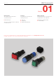
HMI Components Edition 02/2013 Series 01 Characteristics Functions Market segments The compact 16 mm Series 01 is especially suited for: The Series 01 incorporates the following functions: The EAO Series 01 is especially suited for applications in the segments: ■■ Raised design ■■ ■■ This series is ideally suited for combined use with Series 51.
Content 01 01 Overview 02 Raised design Indicator 4 Illuminated pushbutton 6 Accessoires 10 Drawings 22 Technical data 23 Marking 25 Guidelines for use 26 Index 28 03 04 10 14 17 18 19 22 31 41 44 51 56 57 61 70 71 82 84 92 95 96 97 99 ST 3
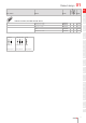
01 01 Raised design Indicator, IP 40 02 Equipment consisting of (schematic overview) 8 max. 03 L1 Lens page 10 Single-LED page 17 39 04 L 10 9 H 34 46 3 Actuator 14 Fixing nut Dimensions [mm] H = Universal terminal 2.0 x 0.5 mm, L = Solder terminal, L1 = Solder terminal 2.8 x 0.5 mm Each Part Number listed below includes all the black components shown in the 3D-drawing. 18 To obtain a complete unit, please select the red components from the pages shown. 18min.
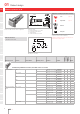
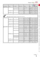
Terminal Part No. Wiring diagram Diode 1N4007 Component layout Raised design 01 01 02 Weight 03 Indicator actuator, Front dimension Ø 18 mm 1 01-741.006 4 Universal 2.0 x 0.5 mm 01-742.006 4 Solder 2.8 x 0.5 mm 01-030.002 Universal 2.0 x 0.5 mm 2 Solder 01-030.005 Universal 2.0 x 0.5 mm 01-031.006 4 1 04 0.008 kg 2 0.008 kg 3 0.006 kg 3 0.006 kg 3 0.
01 01 Raised design Illuminated pushbutton, IP 40 02 L1 8 max. 03 Equipment consisting of (schematic overview) 49 Lens page 10 Single-LED page 17 H 04 L 46 3 10 9 42 … 64.5 H1 14 Product can differ from the current configuration. Dimensions [mm] H = Universal terminal 2.0 x 0.5 mm, H1 = Universal-Solder terminal, L = Solder terminal, L1 = Solder terminal 2.8 x 0.5 mm 18 Additional Information • Each Part Number listed below includes all the black components shown in the 3D-drawing.
Switching system Contacts Diode 1N4007 Switching action Terminal Part No. Wiring diagram 01 Component layout Raised design Weight Snap-action switching element 2Ö+2S 2 B Universal-Solder 01-712.0292 4 21 0.012 kg 1 C Universal-Solder 01-720.0292 4 22 0.012 kg B Solder 01-152.0252 23 0.010 kg 3 NC + 3 NO 4 NC + 4 NO 01 C Solder 01-282.0252 24 0.010 kg B Solder 01-153.0252 25 0.012 kg C Solder 01-283.0252 26 0.012 kg B Solder 01-154.0252 27 0.
01 02 Switching system Contacts Diode 1N4007 Switching action Terminal Part No. Wiring diagram Raised design Component layout 01 Weight 03 04 Illuminated pushbutton actuator, Front dimension Ø 18 mm Low-level element 10 14 17 22 Universal 2.0 x 0.5 mm 01-436.036 4 1 0.009 kg Universal 2.0 x 0.5 mm 01-476.036 4 2 0.009 kg 1 NC + 1 NO B Universal 2.0 x 0.5 mm 01-433.036 4 3 0.009 kg C Universal 2.0 x 0.5 mm 01-473.036 4 4 0.009 kg 1 NO B Universal 2.0 x 0.5 mm 01-435.
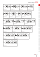
Raised design 1 3 a- 3(+) 1 I 3 a- 3(+) 1(-) 1 I 3 a- 3(+) 1(-) 1 3 01 01 x1- I I 02 2 4 b+ Wiring diagram 12 1 2 4(-) 4 b+ 2 4(-) 2(+) Wiring diagram 13 3 a- 1 I 3 4 b+ 2 4(-) 2(+) Wiring diagram 14 x1- 1 3 I 4 03 x2+ 04 Wiring diagram 15 a- 1 3 I 1 3 a- 10 3(+) II I 14 2 4 2 b+ Wiring diagram 16 1 4 2 x2+ Wiring diagram 17 3 1 3 a- 2 b+ Wiring diagram 18 3(+) 1 II I 4 3 1 2 4 b+ 17 4(-) 18 Wiring diagram 19 3 a-
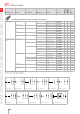
01 Accessories 01 Front 02 Lens plastic 03 04 10 Product attribute 14 17 Dimension 12.8 x 12.8 mm 19 flat, illuminative, not suitable for film insert 12.8 x 12.8 mm 31 41 44 flat, illuminative, less suitable for film insert 12.8 x 12.8 mm 51 56 Part No. Weight Lens plastic flat, illuminative 18 22 Lens flat, non-illuminative 12.8 x 12.8 mm red transparent 01-985.2 0.001 kg orange transparent 01-985.3 0.001 kg yellow transparent 01-985.4 0.001 kg green transparent 01-985.
Accessories 01 01 Product attribute Dimension Lens Part No. 02 Weight 03 Lens plastic flat, illuminative flat, illuminative, not suitable for film insert flat, illuminative, less suitable for film insert flat, non-illuminative Ø 15.8 mm Ø 15.8 mm Ø 15.8 mm Ø 15.8 mm red transparent 01-983.2 04 0.001 kg orange transparent 01-983.3 0.001 kg yellow transparent 01-983.4 0.001 kg green transparent 01-983.5 0.001 kg blue transparent 01-983.6 0.001 kg colourless transparent 01-983.
01 04 • Hinged, with means for sealing • Front panel thickness reduces by 2 mm • Please note that bigger minimum distances are necessary 32 10 25.5 03 Additional Information 23.5 02 Protective cover, IP 40 10.5 01 Accessories 20 10 14.5 12 30 23 10.5 17 23.5 14 24 18 11 Dimensions [mm] 19 22 31 Product attribute Material Optics Plastic transparent Plastic transparent Dimension Part No. Weight 31-920 0.002 kg 01-925 0.
Accessories 01 01 Additional Information 02 • Please note that bigger minimum distances are necessary 18 Protective guard 26 03 12 20 04 10 24 14 Dimensions [mm] 17 18 Product attribute Dimension Material Colour Part No. Weight 19 22 Protective guard narrow ends bent upwards, for button 18 x 24 mm with mounting cut-out Ø16 mm 18 x 26 mm Brass matt chrome 01-926 31 0.
01 Blind plug 02 18min. 18 x 18 mm / Ø18mm 24min. 18 x 24 mm 03 18min. 10.4 04 Ø2 01 Accessories 10 + 0.2 0 Ø16 14 17 Mounting cut-outs [mm] 18 19 Dimension Material Colour Part No. Weight Plastic black 01-948.0 0.001 kg Plastic black 01-947.0 0.001 kg Plastic black 01-949.0 0.
Accessories 01 Rear side 01 PCB plug-in base 02 Additional Information • 03 9.8 2 04 PCB plug-in base pins right-angle: With the extendable mounting the distance between plug-in base and PCB can be varied up to 3 mm 10 14 4 Ø16.4 9.6 3 4 17 17.9 18 6.2 19 17.9 22 9.8 1.5 17.8 31 41 4 12.9 44 Product attribute Pins Terminal Part No. Component layout Dimensions [mm] 51 56 Weight 57 61 PCB plug-in base for low level switching element axial PCB 31-940 3 0.
01 01 Accessories Flat receptacle 02 03 Product attribute Part No. Weight 31-945 0.001 kg 31-946 0.001 kg Part No. Weight 31-928 0.001 kg 31-929 0.001 kg 01-928 0.001 kg 04 10 14 Flat receptacle 2.0 x 0.5 mm plug-in terminal 17 18 19 Flat receptacle 2.8 x 0.5 mm plug-in terminal Insulation sleeve 22 31 41 Product attribute 44 51 Insulation sleeve for flat receptacle 2.0 mm 56 57 Insulation sleeve for flat receptacle 2.
Accessories 01 Illumination 01 Single-LED, T6.
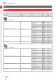
01 Accessories 01 02 LED colour Operating voltage Operation current Lumi. intensity Dom. wavelength Part No. Weight Single-LED white 6 VDC +10 % 15 mA ±15 % 750 mcd x0.31/y0.32 nm 10-2106.3149 0.001 kg 12 VAC/DC +10 % 7/14 mA ±15 % 700 mcd x0.31/y0.32 nm 10-2109.1069 0.001 kg 24 VAC/DC +10 % 7/14 mA ±15 % 700 mcd x0.31/y0.32 nm 10-2112.1069 0.001 kg 28 VAC/DC +10 % 7/14 mA ±15 % 700 mcd x0.31/y0.32 nm 10-2113.1069 0.001 kg 48 VAC/DC +10 % 4/8 mA ±15 % 400 mcd x0.31/y0.
Accessories 01 01 Terminal plate empty 02 Additional Information • For fitting with series resistors 03 04 Product attribute Dimension Part No. 10 Weight 14 Terminal plate empty 5 spaces 62.5 x 60 x 15 mm 02-912.1 0.025 kg 10 spaces 125 x 60 x 15 mm 02-912.2 0.045 kg 15 spaces 187.6 x 60 x 15 mm 02-912.3 0.090 kg 20 spaces 250 x 60 x 15 mm 02-912.4 0.
01 Accessories 01 Mounting 02 Lens remover 03 04 10 Part No. 14 17 18 19 22 Weight Lens remover 02-905 0.011 kg Lamp remover Additional Information p Caution: A switching process might be released when replacing the lamp 31 41 44 Part No. Weight 51 56 57 61 70 Lamp remover 02-906 0.002 kg Mounting tool Additional Information • For tightening or loosening of the fixing nut 71 82 Part No. Weight 84 92 95 Mounting tool 01-907 96 97 99 ST 20 0.
Accessories 01 01 Dressing tool 02 Additional Information • For aligning buttons 03 04 Part No. 10 Weight 14 Dressing tool 01-906 17 0.
01 3.81 Montagestege ausziehbar b 3 1 4 2 4 04 b 10 17.9 9 31 Taste a 42 14 9.6 Ø2.1 Bohrung für eine eventuelle Zentralbefestigung mit M2 Schraube 10.16 3 03 3.81 a 7.62 02 Drawings 7.62 01 Drawings + 0.1 Ø1.0 0 alle Bohrungen 17.9 17 19 1.27 Ø1.0 alle Bohrungen 18 7.62 15.24 22 1.27 5 x 2.54 1.27 Component layout 1 1.27 0.85 Bohrplan (Lötseite) Component layout 2 31 3.81 41 51 Ø2.1 Bohrung für eine eventuelle Zentralbefestigung mit M2 Schraube 5.
Technical data 01 01 Actuator with snap-action switching element Switching system Self-cleaning, double-break, snap action switching system (with contact gap 2 x 0.5 mm). 1 Normally closed or 1 Normally open contact per element. Snap-action switching elements with soldering terminals at the sides: Up to 4 switching element can be on a pushbutton (max. 4 Normally closed and 4 Normally open contacts). Snap-action switching element with axial plug-in terminals 2.
01 Technical data 01 02 03 04 10 14 17 18 19 22 31 41 44 51 56 57 61 70 71 82 84 92 95 96 Approvals Approbations CB (IEC 61058) CSA ENEC (EN 61058) Germanischer Lloyd UL Declaration of conformity CE Actuator with low level switching element Switching system This low level switching element was designed for switching low powers in electronic circuits. The mechanism assures reliable switching of loads ranging from a few μA / μV up to 100 mA / 42 VAC/DC.
Marking 01 01 General notes 3. Film inserts Instead of using engraving the lenses can be fitted with transparent film inserts, as an alternative. For this purpose, though, it is advisible to use transparent lenses. In the case of use of a smokeblack lens the fitted film becomes readable only if the lamp is on. To insert the film, the feet of the lens holder have to be pushed together far enough to enable the lens to be lift off easily. The film thickness is 0.2 mm.
01 01 02 03 04 10 14 17 Application guidelines Suppressor circuits When switching inductive loads such as relays, DC motors, and DC solenoids, it is always important to absorb surges (e. g. with a diode) to protect the contacts. When these inductive loads are switched off, a counter emf can severely damage switch contacts and greatly shorten lifetime. Fig. 1 shows an inductive load with a free-wheeling diode connected in parallel.
Application guidelines 01 01 Diode element for lamp check When indicators and illuminated pushbuttons equipped with diodes, the user is able to perform a lamp check or wire an alarm circuit simply with a considerable saving of space.
01 Index 01 02 03 04 10 14 17 18 19 22 31 41 44 51 56 57 61 70 71 82 84 92 95 96 97 99 ST Index from Part No. Part No. Page 01-030.002................. 5 01-030.005................. 5 01-031.006................. 5 01-040.002................. 4 01-040.005................. 4 01-041.006................. 4 01-050.002................. 4 01-050.005................. 4 01-051.006................. 4 01-121.022................. 7 01-121.0252............... 7 01-122.0252............... 7 01-123.0252...............