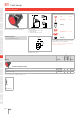
HMI Components Edition 07/2012 Series 51 Characteristics Functions Market segments The compact 16mm Series 51 is particularly suited for applications in the areas: The Series 51 incorporates the following functions: The EAO Series 51 is especially suited for applications in the segments: ■■ ■■ ■■ ■■ Flush design Raised design PCB (with adaptor) ■■ ■■ ■■ ■■ The low level switching element is laid out for low current applications.
Content 51 01 Overview 02 Flush design Indicator 454 Illuminated pushbutton 457 Keylock switch 463 Selector switch 469 03 04 10 Raised design Indicator 479 Illuminated pushbutton 481 Stop switch 485 Keylock switch 486 Selector switch 492 Accessories 497 Drawings 520 Technical data 521 Marking 526 Application guidelines 528 14 17 18 19 22 31 41 44 51 56 57 61 70 71 82 84 92 95 96 97 99 ST 453
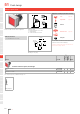
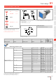
51 01 Flush design Indicator square, IP 65 02 Equipment consisting of (schematic overview) 1.5 ... 4 L1 03 Lens page 497 Single-LED page 515 34 04 L H 10 2 31 41 3 Actuator 14 17 Product can differ from the current configuration. Dimensions [mm] H = Universal terminal 2.0 x 0.5 mm, L = Solder terminal, L1 = Solder terminal 2.8 x 0.
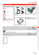
Flush design 51 01 Indicator rectangular, IP 65 Equipment consisting of (schematic overview) Lens 02 1.5 ... 4 L1 page 497 03 34 Single-LED page 515 04 L H Actuator 2 31 10 41 3 14 Front bezel set page 505 Dimensions [mm] H = Universal terminal 2.0 x 0.5 mm, L = Solder terminal, L1 = Solder terminal 2.8 x 0.5 mm Product can differ from the current configuration.
51 01 Flush design Indicator round, IP 65 02 Equipment consisting of (schematic overview) 1.5 ... 4 L1 03 Lens page 497 Single-LED page 515 34 04 L H 10 2 31 41 3 Actuator 14 17 Product can differ from the current configuration. Dimensions [mm] H = Universal terminal 2.0 x 0.5 mm, L = Solder terminal, L1 = Solder terminal 2.8 x 0.
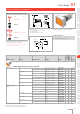
Flush design 51 01 Illuminated pushbutton square, IP 65 Equipment consisting of (schematic overview) Lens 02 1.5 ... 4 L1 page 497 03 44 Single-LED page 515 04 L H Actuator 2 36.5 … 59 10 41 3 14 Front bezel set page 505 Dimensions [mm] H = Universal terminal 2.0 x 0.5 mm, L = Solder terminal, L1 = Solder terminal 2.8 x 0.5 mm Product can differ from the current configuration.
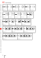
51 01 Flush design 1 a- 1 a- 1 3 a- 1 3 a- 1 a- 1 a- 2 b+ 2 b+ 2 4 b+ 2 4 b+ 2 b+ 2 b+ 02 03 04 Wiring diagram 1 10 1 Wiring diagram 2 3 a- Wiring diagram 3 1 3 Wiring diagram 4 a- 1 3 Wiring diagram 5 a- 1 3 Wiring diagram 6 a- 1 3 a- 4 b+ I 14 17 18 2 4 2 b+ Wiring diagram 7 19 1 4 b+ Wiring diagram 8 3 x1- b+ 3 a- 4 2 Wiring diagram 9 1 I 4 2 2 b+ Wiring diagram 10 1 I 3 x1- Wiring diagram 11 1 I 3 1 I 3 x1- 4 x
Flush design 51 01 Illuminated pushbutton rectangular, IP 65 Equipment consisting of (schematic overview) Lens 02 1.5 ... 4 L1 page 497 03 44 Single-LED page 515 04 L H Actuator 2 36.5 … 59 10 41 3 14 Front bezel set page 505 Dimensions [mm] H = Universal terminal 2.0 x 0.5 mm, L = Solder terminal, L1 = Solder terminal 2.8 x 0.5 mm Product can differ from the current configuration.
51 01 Flush design 1 a- 1 a- 1 3 a- 1 3 a- 1 a- 1 a- 2 b+ 2 b+ 2 4 b+ 2 4 b+ 2 b+ 2 b+ 02 03 04 Wiring diagram 1 10 1 Wiring diagram 2 3 a- Wiring diagram 3 1 3 Wiring diagram 4 a- 1 3 Wiring diagram 5 a- 1 3 Wiring diagram 6 a- 1 3 a- 4 b+ I 14 17 18 2 4 2 b+ Wiring diagram 7 19 1 4 b+ Wiring diagram 8 3 x1- b+ 3 a- 4 2 Wiring diagram 9 1 I 4 2 2 b+ Wiring diagram 10 1 I 3 x1- Wiring diagram 11 1 I 3 1 I 3 x1- 4 x
Flush design 51 01 Illuminated pushbutton round, IP 65 Equipment consisting of (schematic overview) Lens 02 1.5 ... 4 L1 page 497 03 44 Single-LED page 515 04 L H Actuator 2 36.5 … 59 10 41 3 14 Front bezel set page 505 Dimensions [mm] H = Universal terminal 2.0 x 0.5 mm, L = Solder terminal, L1 = Solder terminal 2.8 x 0.5 mm Product can differ from the current configuration.
51 01 Flush design 1 a- 1 a- 1 3 a- 1 3 a- 1 a- 1 a- 2 b+ 2 b+ 2 4 b+ 2 4 b+ 2 b+ 2 b+ 02 03 04 Wiring diagram 1 10 1 Wiring diagram 2 3 a- Wiring diagram 3 1 3 Wiring diagram 4 a- 1 3 Wiring diagram 5 a- 1 3 Wiring diagram 6 a- 1 3 x1- 4 x2+ I 14 17 18 2 4 2 b+ Wiring diagram 7 19 1 4 b+ Wiring diagram 8 3 a- b+ 3 a- 4 2 Wiring diagram 9 1 I 4 2 2 b+ Wiring diagram 10 1 3 I x1- Wiring diagram 11 1 I 3 1 I 3 x1- 4
Flush design 51 01 Keylock switch 2 positions, IP 65 02 1.5 ... 5 Equipment consisting of (schematic overview) L1 03 44.5 L Actuator 04 H 3.5 Front bezel set 35 … 57.5 41.5 page 507 14 Dimensions [mm] H = Universal terminal 2.0 x 0.5 mm, L = Solder terminal, L1 = Solder terminal 2.8 x 0.5 mm Anti-twist ring Part of front bezel set 10 3 27 Product can differ from the current configuration.
01 02 03 Wiring diagram Flush design Component layout 51 Switching system Contacts Switching action Switching angle Key remove Terminal Part No. Snap-action switching element 1 NC + 1 NO A-C C = 90° C Solder 2.8 x 0.5 mm 51-355.022DF 9 0.027 kg A+C Solder 2.8 x 0.5 mm 51-155.022DF 9 0.027 kg 2 NC + 2 NO A-C C = 90° 04 10 3 NC + 3 NO 14 4 NC + 4 NO A-C A-C C = 90° C = 90° 17 Weight A Solder 51-256.025D2F 10 0.027 kg C Solder 51-356.025D2F 10 0.
Contacts Switching action Switching angle Key remove Terminal Part No. Wiring diagram Switching system Component layout Flush design 51 01 Weight 02 03 Keylock switch actuator 2 positions round, flush design Low-level element 1 NC + 1 NO A-B B = 42° A Universal 2.0 x 0.5 mm 51-438.036DF 4 1 0.026 kg 2 NO A-B B = 42° A Universal 2.0 x 0.5 mm 51-437.036DF 4 2 0.026 kg 1 NC + 1 NO A-C C = 90° A Universal 2.0 x 0.5 mm 51-415.036DF 4 7 0.
51 Flush design 01 1 3 1 3 1 3 I 02 03 04 4 2 Wiring diagram 1 10 4 2 Wiring diagram 2 1 3 1 I 2 4 Wiring diagram 3 3 1 II 3 1 I 3 1 II 3 III 14 17 18 2 4 2 Wiring diagram 4 19 2 2 4 3 1 3 1 3 4 2 4 2 4 4 4 2 4 Wiring diagram 5 1 3 1 I 3 1 II 3 1 III IV 22 31 41 2 4 2 4 2 4 2 Wiring diagram 6 44 Wiring diagram 7 1 1 3 3 1 I I 3 Wiring diagram 8 1 II 3 1 I 3 1 II 3 III 51 56 57 2 Wiring diagram 9 61 2 4 4
Flush design 51 01 Keylock switch 3 positions, IP 65 02 1.5 ... 5 Equipment consisting of (schematic overview) 03 04 Actuator 3.5 Front bezel set 10 50 27 page 507 14 Dimensions [mm] Anti-twist ring Product can differ from the current configuration.
Flush design 01 02 Switching system Contacts Switching action Switching angle Key remove Terminal Part No. Wiring diagram 51 Weight 03 04 10 Keylock switch actuator 3 positions rectangular, flush design Snap-action switching element 2 NC + 2 NO B-A-B B = 42° / 42° A Solder 2.8 x 0.5 mm 51-364.022DF 1 0.027 kg C-A-B C = 90°, B = 42° A Solder 2.8 x 0.5 mm 51-367.022DF 2 0.027 kg A+C Solder 2.8 x 0.5 mm 51-368.022DF 2 0.
Flush design 51 01 Selector switch 2 positions square, IP 65 02 1.5 ... 6 Equipment consisting of (schematic overview) L1 Lever page 503 Single-LED page 515 03 48 04 L 10 H 2 Actuator Front bezel set 9.5 41 … 63.5 45 3 Dimensions [mm] H = Universal terminal 2.0 x 0.5 mm, L = Solder terminal, L1 = Solder terminal 2.8 x 0.5 mm page 508 14 Product can differ from the current configuration.
Flush design 02 03 04 10 Switching system Contacts Switching action Switching angle Terminal Part No. Wiring diagram 01 Component layout 51 Weight Snap-action switching element 2 NC + 2 NO A-C C = 90° Solder 52-272.0252 18 0.006 kg 3 NC + 3 NO A-C C = 90° Solder 52-273.0252 19 0.006 kg 4 NC + 4 NO A-C C = 90° Solder 52-274.0252 20 0.
Flush design 1 3 x1- 1 I 3 a- 1 I 3 1 I 3 51 01 x1- II 02 2 4 2 x2+ Wiring diagram 16 4 Wiring diagram 17 1 3 1 I 3 1 II 3 2 b+ 2 4 4 03 x2+ 04 Wiring diagram 18 x1- 1 III 3 1 I 3 1 II 3 1 III 3 10 x1- IV 14 2 Wiring diagram 19 4 2 4 2 4 2 x2+ 4 2 4 2 4 2 4 17 x2+ 18 Wiring diagram 20 19 22 31 41 44 51 56 57 61 70 71 82 84 92 95 96 97 99 ST 471
51 01 Flush design Selector switch 2 positions round, IP 65 02 1.5 ... 6 Equipment consisting of (schematic overview) L1 03 48 04 L 10 9.5 Product can differ from the current configuration. 45 Dimensions [mm] H = Universal terminal 2.0 x 0.5 mm, L = Solder terminal, L1 = Solder terminal 2.8 x 0.
51 01 Switching system Contacts Switching action Switching angle Terminal Part No. Wiring diagram Component layout Flush design Weight Snap-action switching element 2 NC + 2 NO A-C C = 90° Solder 52-272.0252 18 0.006 kg 3 NC + 3 NO A-C C = 90° Solder 52-273.0252 19 0.006 kg 4 NC + 4 NO A-C C = 90° Solder 52-274.0252 20 0.
51 Flush design 01 1 3 x1- 1 I 3 a- 1 I 3 1 I 3 x1- 4 x2+ II 02 03 04 2 4 2 x2+ Wiring diagram 16 10 4 Wiring diagram 17 1 3 1 I 3 1 II 3 2 b+ 2 4 Wiring diagram 18 x1- 1 III 3 1 I 3 1 II 3 1 III 3 x1- 4 x2+ IV 14 17 18 2 Wiring diagram 19 19 22 31 41 44 51 56 57 61 70 71 82 84 92 95 96 97 99 ST 474 4 2 4 2 4 2 x2+ Wiring diagram 20 4 2 4 2 4 2
Flush design 51 01 Selector switch 3 positions square, IP 40 02 1.5 ... 5 Equipment consisting of (schematic overview) Lever page 503 03 Single-LED page 515 04 10 2 Actuator 9.5 50 14 Dimensions [mm] Front bezel set Product can differ from the current configuration.
51 01 Flush design 1 3 1 C 3 a- 1 B 3 1 C 3 a- 4 b+ 3 a- 4 b+ B 02 03 2 04 Wiring diagram 1 10 1 4 2 4 b+ 2 4 2 3 1 Wiring diagram 2 3 1 C 3 a- 1 B C B 14 17 2 18 Wiring diagram 3 19 22 31 41 44 51 56 57 61 70 71 82 84 92 95 96 97 99 ST 476 4 2 4 b+ 2 Wiring diagram 4 4 2
Flush design 51 01 Selector switch 3 positions round, IP 40 02 1.5 ... 5 Equipment consisting of (schematic overview) Lever page 503 03 Single-LED page 515 04 10 2 Actuator 9.5 Front bezel set 50 Dimensions [mm] page 508 14 Product can differ from the current configuration.
51 01 Flush design 1 3 1 C 3 a- 1 B 3 1 C 3 a- 4 b+ 3 a- 4 b+ B 02 03 2 04 Wiring diagram 1 10 1 4 2 4 b+ 2 4 2 3 1 Wiring diagram 2 3 1 C 3 a- 1 B C B 14 17 2 18 Wiring diagram 3 19 22 31 41 44 51 56 57 61 70 71 82 84 92 95 96 97 99 ST 478 4 2 4 b+ 2 Wiring diagram 4 4 2
Raised design 51 01 Indicator, IP 65 02 Equipment consisting of (schematic overview) Lens 1.5 ... 6 page 498 03 L1 26 Single-LED page 515 04 L H Actuator 10.5 23 32 10 3 14 Fixing nut Dimensions [mm] H = Universal terminal 2.0 x 0.5 mm, L = Solder terminal, L1 = Solder terminal 2.8 x 0.5 mm Product can differ from the current configuration. 17 18 Each Part Number listed below includes all the black components shown in the 3D-drawing. 24min.
01 02 Diode 1N4007 Terminal Part No. Wiring diagram Raised design Component layout 51 Weight 03 04 10 Indicator actuator, Front dimension Ø 18 mm 1 Universal 2.0 x 0.5 mm 51-741.006 4 3 0.006 kg 2 Universal 2.0 x 0.5 mm 51-742.006 4 2 0.
Raised design 51 01 Illuminated pushbutton, IP 65 Equipment consisting of (schematic overview) Lens page 498 Single-LED page 515 1.5 … 6 02 L1 03 36 H L 04 32 10.5 28 … 50.5 3 10 H1 Actuator 43.5 / 51 Dimensions [mm] H = Universal terminal 2.0 x 0.5 mm, H1 = Universal-Solder terminal, L = Solder terminal, L1 = Solder terminal 2.8 x 0.5 mm Fixing nut Each Part Number listed below includes all the black components shown in the 3D-drawing.
Raised design 02 03 Switching system Contacts Snap-action switching element 3 NC + 3 NO Diode 1N4007 4 NC + 4 NO 04 Switching action Terminal Part No. Wiring diagram 01 Component layout 51 Weight B Solder 51-153.0252 25 0.010 kg C Solder 51-283.0252 26 0.010 kg B Solder 51-154.0252 27 0.012 kg C Solder 51-284.0252 28 0.012 kg 10 14 Illuminated pushbutton actuator, Front dimension 18 x 24 mm 1 NC B Universal 2.0 x 0.5 mm 51-426.036 4 1 0.
51 01 Switching action Terminal Part No. Wiring diagram Component layout Raised design Weight B Solder 51-132.0252 23 0.008 kg C Solder 51-272.0252 24 0.008 kg 3 NC + 3 NO B Solder 51-133.0252 25 0.010 kg C Solder 51-273.0252 26 0.010 kg 4 NC + 4 NO B Solder 51-134.0252 27 0.012 kg C Solder 51-274.0252 28 0.
51 01 Raised design 1 3 1 I 3 x1- 1 II 3 1 I 3 x1- 1 II 3 1 I 3 1 II 3 x1- 4 x2+ III 02 03 04 2 4 2 4 2 x2+ Wiring diagram 23 10 1 2 4 4 2 x2+ Wiring diagram 24 3 1 I 3 1 II 3 2 4 2 4 Wiring diagram 25 x1- 1 III 3 1 I 3 1 II 3 1 III 3 x1- 4 x2+ IV 14 17 18 2 4 2 4 2 4 2 x2+ Wiring diagram 26 19 1 Wiring diagram 27 3 1 I 3 1 II 3 1 III 3 x1- 4 x2+ IV 22 31 41 2 Wiring diagram 28 44 51 56 57 61 70 71 82 84 92
Raised design 51 01 Stop switch complete, IP 65 Equipment consisting of (schematic overview) 02 1 ... 3 L1 Actuator 03 27.6 L 04 H Anti-twist ring 19 26.3 24 Fixing nut Each Part Number listed below includes all the black components shown in the 3D-drawing. 10 18.8 3 14 Dimensions [mm] H = Universal terminal 2.0 x 0.5 mm, L = Solder terminal, L1 = Solder terminal 2.8 x 0.5 mm Product can differ from the current configuration.
51 01 Raised design Keylock switch 2 positions, IP 65 02 Equipment consisting of (schematic overview) 1.5 … 6 L1 03 36 L 04 10 11.5 26.5 … 49 32.5 35 14 17 Actuator H Product can differ from the current configuration. 3 Anti-twist ring Dimensions [mm] H = Universal terminal 2.0 x 0.5 mm, L = Solder terminal, L1 = Solder terminal 2.8 x 0.
51 01 Switching system Contacts Switching action Switching angle Key remove Terminal Part No. Wiring diagram Component layout Raised design Weight Snap-action switching element 1 NC + 1 NO A-C C = 90° A+C Solder 2.8 x 0.5 mm 51-155.022D 9 0.016 kg 2 NC + 2 NO A-C C = 90° A Solder 51-256.025D2 10 0.016 kg C Solder 51-356.025D2 10 0.016 kg A+C Solder 51-156.025D2 10 0.016 kg A Solder 51-257.025D2 11 0.016 kg A+C Solder 51-157.025D2 11 0.
Wiring diagram Raised design Component layout 51 Weight A-B B = 42° A Universal 2.0 x 0.5 mm 51-438.036D 4 1 0.017 kg A-C C = 90° A Universal 2.0 x 0.5 mm 51-415.036D 4 7 0.017 kg C Universal 2.0 x 0.5 mm 51-418.036D 4 7 0.017 kg A+C Universal 2.0 x 0.5 mm 51-412.036D 4 7 0.017 kg A Universal 2.0 x 0.5 mm 51-414.036D 4 8 0.017 kg A+C Universal 2.0 x 0.5 mm 51-411.036D 4 8 0.
51 Raised design 1 3 1 3 1 01 3 I 02 4 2 Wiring diagram 1 4 2 Wiring diagram 2 1 3 1 I 2 03 4 04 Wiring diagram 3 3 1 II 3 1 I 3 1 II 10 3 III 14 2 4 2 2 4 Wiring diagram 4 4 2 4 2 17 4 18 Wiring diagram 5 1 3 1 I 3 1 II 3 1 III 3 1 3 1 19 3 IV 22 2 4 2 4 2 4 2 4 2 Wiring diagram 6 Wiring diagram 7 1 3 1 I 3 1 I 3 4 31 4 2 41 Wiring diagram 8 1 II 3 1 I 3 1 II 44 3 III 51 2 2 4 Wiring diagram 9 4 Wiring
51 01 Raised design Keylock switch 3 positions, IP 65 02 1.5 ... 6 Equipment consisting of (schematic overview) 03 04 Actuator 10 11.5 14 17 42 35 Product can differ from the current configuration.
Switching system Contacts Switching action Switching angle Key remove Terminal Part No. Wiring diagram Raised design 51 01 Weight 02 03 Keylock switch 3 positions, Front dimension Ø 18 mm Snap-action switching element 2 NC + 2 NO B-A-B B = 42° / 42° C-A-B C = 90°, B = 42° Solder 2.8 x 0.5 mm 51-374.022D A 1 0.025 kg A Solder 2.8 x 0.5 mm 51-377.022D 3 0.025 kg A+C Solder 2.8 x 0.5 mm 51-378.022D 3 0.025 kg B-A-C B = 42°, C = 90° C+A Solder 2.8 x 0.5 mm 51-376.022D 2 0.
51 01 Raised design Selector switch 2 positions, IP 65 02 1.5 … 6 Equipment consisting of (schematic overview) L1 03 36 36 10 6 14 18 19 32 … 54.5 Fixing nut NJO Y NN • NJO Y NN ± NN 31 41 ± 44 56 Anti-twist ring Additional Information 22 51 Actuator Dimensions [mm] H = Universal terminal 2.0 x 0.5 mm, H1 = Universal-Solder terminal, L = Solder terminal, L1 = Solder terminal 2.8 x 0.5 mm Illuminative page 515 43.
51 01 Switching system Contacts Diode 1N4007 Switching action Switching angle Terminal Part No. Wiring diagram Component layout Raised design Weight Snap-action switching element 2 NC + 2 NO 1 A-B B = 42° Universal-Solder 52-745.0292 10 0.010 kg 2 A-B B = 42° Universal-Solder 52-746.0292 11 0.010 kg A-B B = 42° Solder 52-132.0252 12 0.006 kg 3 NC + 3 NO A-B B = 42° Solder 52-133.0252 13 0.006 kg 4 NC + 4 NO A-B B = 42° Solder 52-134.0252 14 0.
51 Raised design 01 1 3 1 I 3 1 II 3 x1- 1 3 III 1 I 3 1 II 3 1 III 3 x1- 4 x2+ IV 02 03 04 2 2 4 2 4 4 Wiring diagram 13 10 2 x2+ 2 4 2 4 2 4 Wiring diagram 14 1 a- 1 3 a- 1 a- 1 3 a- 2 b+ 2 4 b+ 2 b+ 2 4 b+ 14 17 18 Wiring diagram 15 19 Wiring diagram 16 1 3 a- 1 3 Wiring diagram 17 Wiring diagram 18 a- 1 3(+) I 3 a- 3(+) 1(-) 4 b+ 4(-) 2(+) I 22 31 41 4 2 2 b+ Wiring diagram 19 44 4 b+ Wiring diagram 20 1 3
Raised design 51 01 Selector switch 3 positions, IP 65 02 1.5 ... 6 Equipment consisting of (schematic overview) Lever page 503 03 Single-LED page 515 04 10 6 Actuator 14 42 14 Dimensions [mm] Anti-twist ring Product can differ from the current configuration. Fixing nut Additional Information NJO Y NN ± NN • Each Part Number listed below includes all the black components shown in the 3D-drawing.
51 01 Raised design 1 3 1 C 3 a- 1 3 1 C B 3 a- 4 b+ 3 a- 4 b+ B 02 03 2 04 Wiring diagram 1 10 1 4 2 4 b+ 2 4 2 3 1 Wiring diagram 2 3 1 C 3 a- 1 B C B 14 17 2 18 Wiring diagram 3 19 22 31 41 44 51 56 57 61 70 71 82 84 92 95 96 97 99 ST 496 4 2 4 b+ 2 Wiring diagram 4 4 2
Raised design 51 Front 01 Lens flush design 02 03 Additional Information • Surface mat • Lens profile flat 04 10 14 Product attribute Dimension Lens Part No. Weight 17 18 Lens plastic, flush design illuminative 18 x 18 mm non-illuminative 18 x 18 mm smoked transparent 61-9671.1 19 0.002 kg red transparent 61-9671.2 0.002 kg orange transparent 61-9671.3 0.002 kg yellow transparent 61-9671.4 0.002 kg green transparent 61-9671.5 0.002 kg blue transparent 61-9671.6 0.
51 01 Raised design Lens raised design 02 03 Product attribute Dimension Lens Part No. Weight 15.3 x 15.3 mm smoked transparent 51-953.1 0.001 kg 04 10 14 Lens plastic, raised design flat, illuminative 17 18 19 flat, illuminative, not suitable for film insert 15.3 x 15.3 mm red transparent 51-953.2 0.001 kg orange transparent 51-953.3 0.001 kg yellow transparent 51-953.4 0.001 kg green transparent 51-953.5 0.001 kg blue transparent 51-953.6 0.
Raised design 51 01 Product attribute Dimension Lens Part No. Weight flat, illuminative, not suitable for film insert 15.3 x 21.5 mm red translucent 51-901.2 0.001 kg orange translucent 51-901.3 0.001 kg yellow translucent 51-901.4 0.001 kg flat, illuminative, less suitable for film insert flat, non-illuminative 15.3 x 21.5 mm 15.3 x 21.5 mm green translucent 51-901.5 0.001 kg blue translucent 51-901.6 0.001 kg white translucent 51-901.9 0.001 kg red transparent 51-905.2 0.
51 01 02 03 04 Accessories Lens plastic with symbol Additional Information • Lens profile flat • Illuminative • The silvery coat is being applied on the lens (screen print) with an additional protective lacquer. Further information see «Technical data» 10 14 17 Dimension Lens Symbol Part No. Weight 18 19 Lens plastic with symbol, flush design red transparent Ring 61-9643.201 0.002 kg orange transparent Ring 61-9643.301 0.002 kg 22 yellow transparent Ring 61-9643.401 0.
Accessories 51 01 Lens metal with spot 02 Additional Information • Lens surface mat • Lens profile flat • Illuminative 03 04 10 Dimension Lens Part No. 14 Weight 17 18 Lens metal with spot, flush design Ø 19.7 mm 61-9841.0A Aluminium black anodized 0.002 kg Aluminium red anodized 61-9841.2A 0.002 kg Aluminium gold anodized 61-9841.4A 0.002 kg Aluminium olive-green anodized 61-9841.5A 0.002 kg Aluminium blue anodized 61-9841.6A 0.002 kg Aluminium natural anodized 61-9841.
51 01 02 03 Accessories Mushroom-head cap Additional Information • Non-illuminative 04 10 Mushroom-head cap Part No. Weight 14 17 Mushroom-head cap, flush design, Front dimension Ø 32 mm 18 Plastic black 61-9593.0 0.004 kg Plastic red 61-9593.2 0.004 kg 19 Plastic yellow 61-9593.4 0.004 kg Plastic green 61-9593.5 0.004 kg Part No.
Accessories 51 01 Lever flush design 02 Additional Information • With bar and marking dot 03 04 Lever illumination Lever Bar colour Part No. 10 Weight 14 Lever flush design illuminative Plastic black Plastic grey non-illuminative Plastic black Plastic grey 61-9028.20 red 17 0.001 kg yellow 61-9028.40 0.001 kg green 61-9028.50 0.001 kg blue 61-9028.60 0.001 kg red 61-9029.20 0.001 kg orange 61-9029.30 0.001 kg yellow 61-9029.40 0.001 kg green 61-9029.50 0.
51 • The colour of anodized aluminium parts can vary due to technical production reasons 04 14.5 For devices with front dimension Ø 25 mm, flush design 4 23.5 • Ø25 03 Additional Information 35 ± 0.3 02 Legend frame 50 ± 0.3 01 Accessories 10 0 30 -0.1 14 Dimensions [mm] 17 18 19 Dimension Material Colour Mounting type Part No. Weight black anodized adhesive 61-9980.0 0.001 kg Colour Mounting type Part No. Weight natural anodized adhesive 704.968.0 0.
Accessories 51 01 Front bezel set illuminated pushbutton 02 Additional Information • The dimensions of the mounting cut-outs are shown in the product details • The colour of anodized aluminium parts can vary due to technical production reasons 03 04 10 Mounting cut-out Front bezel Part No. 14 Weight 17 18 Front bezel set for indicator and illuminated pushbutton, flush design, Front dimension 24 x 24 mm 21 x 21 mm Plastic black 61-9930.0 0.008 kg Plastic silver 61-9930.4 0.
51 01 02 03 Accessories Front bezel set mushroom-head pushbutton Additional Information • Please note that bigger minimum distances are necessary • The colour of anodized aluminium parts can vary due to technical production reasons 04 10 14 Dimension Mounting cut-out Front bezel Part No. Weight 17 18 19 Front bezel set for mushroom-head pushbutton, flush design Ø 25 mm Ø 22.5 mm Aluminium natural anodized 61-9933.0 0.006 kg Aluminium black anodized 61-9933.1 0.
Accessories 51 01 Front bezel set keylock switch 02 Additional Information • The Dimensions [mm] of the Mounting cut-outs [mm] are shown in the product details • For the round front bezel sets the anti-twist ring is part of the sales-package • The colour of anodized aluminium parts can vary due to technical production reasons 03 04 10 14 Mounting cut-out Front bezel Part No.
51 01 02 03 04 Accessories Frontrahmen-Set Wahlschalter Additional Information • The dimensions of the mounting cut-outs are shown in the product details • For the round front bezel sets the anti-twist ring is part of the sales-package • The colour of anodized aluminium parts can vary due to technical production reasons 10 14 17 Mounting cut-out Front bezel Part No. Weight 61-9936.0 0.
Accessories 51 01 Protective cover flush design, IP 65 Additional Information • Please note that bigger minimum distances are necessary 03 25 The Dimensions [mm] of the Mounting cut-outs [mm] are shown in the product details 02 24 04 12 • 5.5 max. 24 10 4.5 24 14 17 12 25 5.5 max. 30 18 4.5 19 10 29.3 1.5 min. 22 5.5 max. 42 31 41 Ø 25 44 Dimensions [mm] 51 Product attribute Dimension Mounting cut-out Material Optics Part No.
51 04 32 • Hinged, with means for sealing • The dimensions of the mounting cut-outs are shown in the product details • Please note that bigger minimum distances are necessary 20 25.5 03 Additional Information 23.5 02 Protective cover raised design, IP 65 10.5 01 Accessories 14.5 10 17 24 18 25.5 10.5 14 23.5 32 14.5 Dimensions [mm] 19 22 Dimension Mounting cut-out Material Optics Part No. Weight Plastic transparent 51-920 0.002 kg Plastic transparent 51-925 0.
Accessories 51 01 Blind plug raised design 02 Additional Information • The dimensions of the mounting cut-outs are shown in the product details • Blind plugs fit also in mounting cut-outs with antitwist device 03 04 10 Dimension Mounting cut-out Material Colour Part No. 14 Weight 17 18 Blind plug raised design 18 x 18 mm Ø 16 mm Plastic black 51-948.0 0.003 kg 19 22 Blind plug raised design 18 x 24 mm Ø 16 mm Plastic black 51-947.0 31 0.
51 01 02 03 Accessories Spare key Additional Information • For standard lock: DOM 311 • Optional lock numbers on request 04 10 14 Part No. 17 18 19 22 31 Weight Spare key 31-989.311 0.006 kg EMC key protection cap Additional Information • Plastic black • For standard lock: DOM 41 44 51 Part No. Weight 56 57 EMC key protection cap 31-985.0 61 70 71 82 84 92 95 96 97 99 ST 512 0.
Accessories 51 Rear side 01 PCB plug-in base 02 03 Additional Information 04 PCB plug-in base pins right-angle: With the extendable mounting the distance between plug-in base and PCB can be varied up to 3 mm Product attribute 10 Dimension pins Terminal Part No. Component layout • 14 17 Weight 18 PCB plug-in base for low level switching element Ø 16.4 x 9.8 mm axial PCB 31-940 3 19 0.002 kg 22 31 PCB plug-in base for low level switching element 17.9 x 17.9 x 9.
51 01 Accessories Flat receptacle 02 03 Product attribute Part No. Weight 31-945 0.001 kg 31-946 0.001 kg 51-943.1 0.001 kg Part No. Weight 01-928 0.001 kg 31-928 0.001 kg 31-929 0.001 kg 04 10 14 Flat receptacle 2.0 x 0.5 mm plug-in terminal 17 18 Flat receptacle 2.8 x 0.5 mm plug-in terminal 19 22 Flat receptacle 2.8 x 0.
Accessories 51 Illumination 01 Single-LED, T1 3/4 MG 02 03 Additional Information 04 Luminous intensity data of the LEDs on direct voltage • Electrical and optical data are measured at 25 °C • The specified versions are built with a protection diode (halve wave rectifier) in series and the LED • When using AC/DC types with AC operation, slight flickering can occure • Luminosity and wave length variations caused by LED manufacturing processes may cause slight differences regarding the illumin
51 01 Accessories Filament lamp, T1 3/4 MG 02 03 Operating voltage Operation current Part No. Weight 04 10 Filament lamp 14 6 VAC/DC 120 mA ±10 % 10-1306.1349 0.001 kg 6.3 VAC/DC 200 mA ±10 % 10-1307.1369 0.001 kg 17 12 VAC/DC 75 mA ±10 % 10-1309.1309 0.001 kg 14 VAC/DC 80 mA ±10 % 10-1310.1319 0.001 kg 18 VAC/DC 40 mA ±10 % 10-1311.1249 0.001 kg 18 19 22 31 41 44 51 56 57 24 VAC/DC 35 mA ±10 % 10-1312.1229 0.001 kg 28 VAC/DC 30 mA ±10 % 10-1313.1209 0.
Accessories 51 01 Terminal plate empty 02 Additional Information • For fitting with series resistors 03 04 Product attribute Dimension Part No. 10 Weight 14 Terminal plate empty 5 spaces 62.5 x 60 x 15 mm 02-912.1 17 0.025 kg 10 spaces 125 x 60 x 15 mm 02-912.2 0.045 kg 15 spaces 187.6 x 60 x 15 mm 02-912.3 0.090 kg 20 spaces 250 x 60 x 15 mm 02-912.4 0.
51 Accessories 01 Mounting 02 Fixing nut 03 04 Additional Information • Special recommended for keylock switches 10 14 Material Part No. Weight 31-991 0.005 kg 17 18 19 22 31 41 Fixing nut Metal Anti-twist ring Additional Information • For key lock- and selector switch 44 51 Part No. Weight 56 57 Anti-twist ring 51-910 0.001 kg 61 70 Lens remover 71 82 Product attribute Part No. Weight 84 92 Lens remover for raised design 02-905 0.
Accessories 51 01 Lamp remover 02 Additional Information p Caution: A switching process might be released 03 when replacing the lamp 04 Part No. 10 Weight 14 17 Lamp remover 61-9740.0 18 0.003 kg 19 Mounting tool 22 31 Product attribute Part No. Weight 41 44 Mounting tool for device with mounting cut-out Ø 16 mm, for tightening or loosening of the fixing nut 01-907 51 0.
51 3.81 Extendable mounting pins b 3 1 4 2 4 04 17.9 b 10 a 42 14 9.6 Ø2.1 hole for central mounting with M2 screw, if desired +0.1 Ø1.0 0 all holes 17.9 17 1.27 Ø1.0 all holes 7.62 15.24 18 22 1.27 5 x 2.54 1.27 Component layout 1 1.27 Drilling plan (solder side) 0.85 19 9 31 Switch 10.16 3 03 3.81 a 7.62 02 Drawings 7.62 01 Drawings Component layout 2 31 3.81 41 Ø1.0 56 5.08 Ø2.1 hole for central mounting with M2 screw, if desired 10.
Technical data 51 01 Actuator with snap-action switching element block (Keylock- and Selector switch 3 positions) Switching system Electrical characteristics Self-cleaning, double-break snap action switching system 1 normally closed and 1 normally open contact per element. Electrostatic discharge (ESD) ≤ 15 KV (Keylock switch) Material Material of contact Gold plated hardsilver Switch housing Diallylphthalate (DAP), heat-resistant and self-extinguishing 04 Switch rating 250 VAC, 5 A (cosφ 0.
51 01 02 03 04 10 14 Technical data Actuator with low level switching element Switching system This low level switching element was designed for switching low powers in electronic circuits. The mechanism assures reliable switching of loads ranging from a few μA/μV up to 100 mA/ 42 VAC/DC. Single-break momentary contact, as normally open or normally closed with 4 independent points of contact. 2 momentary contacts per switching element; combination of normally open and normally closed is possible.
Technical data 51 01 Actuator with snap-action switching element Switching system Self-cleaning, double-break snap action switching system (with contact gap 2 x 0.5 mm). 1 normally closed and 1 normally open contact per element. Snap-action switching elements with soldering terminals at the sides: up to 4 switching element can be on a pushbutton (max. 4 normally closed and 4 normally open contacts). Snap-action switching element with axial plug-in terminals 2.
51 Technical data 01 02 03 04 10 14 17 18 19 22 31 41 44 51 56 57 61 70 Shock resistance (Single impacts, semi-sinusoidal) 15 g for 11 ms, as per IEC 60512-4-3, IEC 60068-2-27 Vibration resistance (Sinusoidal) 10 g at 10 Hz … 1500 Hz, amplitude 0.75 mm, as per IEC 60512-4-4, IEC 60068-2-6 Climate resistance Standard condition, as per IEC 60068-2-3 and 2-30 Changing condition, as per IEC 60068-2-14 and 2-33 Switching system Switching element SE 2.
Technical data 51 01 Lens plastic with symbols Chemical and mechanical tests 02 1. Wipe resistance according to EN 61058-1 section 8.9 (Petrol/gasoline, distilled water, diluted alcohol) 2. Graffiti-Killer Test 3. Railway cleaning agents (Walo) 4. Damp/dry heat durability 5. UV test according to EN 60068-2-5 / 56 days 6. Mechanical life time 2 Mio. Operations (abrasive test) 03 04 10 14 17 EAO reserves the right to alter specifications without further notice.
51 01 02 03 04 10 14 Marking General notes 3. Film inserts Instead of using engraving the lenses can be fitted with transparent film inserts, as an alternative. For this purpose, though, it is advisible to use transparent lenses. In the case of use of a smoke-black lens the fitted film becomes readable only if the lamp is on. The film thickness is 0.2 mm. Important : Consider pushbutton mounting orientation befor specifying engraving characters! 1.
Marking 51 01 Lenses for indicators and illuminated pushbuttons, flush mounting All dimensions in mm Front size (Lens) Film insert max. size Height of letters h Number of lines Number of capital letters per line (target value) 24 x 24 (18 x 18) 15.1 x 15.1 2 4 8–9 15.
51 01 02 03 04 10 14 17 Application guidelines Suppressor circuits When switching inductive loads such as relays, DC motors, and DC solenoids, it is always important to absorb surges (e. g. with a diode) to protect the contacts. When these inductive loads are switched off, a counter emf can severely damage switch contacts and greatly shorten lifetime. Fig. 1 shows an inductive load with a free-wheeling diode connected in parallel.