
Datasheet


456
01
02
03
04
10
14
17
18
19
22
31
41
44
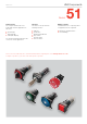
51
56
57
61
70
71
82
84
92
95
96
97
99
ST
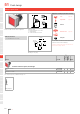
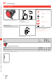
Flush design
31
2
34
1.5 ... 4
41 3
L1
H
L
NJO
NJO
±
a-(x1)
b+(x2)
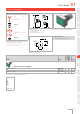
Wiring diagram 1
Indicator round, IP 65
Product can differ from the current configuration. Dimensions [mm]
H = Universal terminal 2.0 x 0.5 mm,
L = Solder terminal,
L1 = Solder terminal 2.8 x 0.5 mm
Mounting cut-outs [mm]
Additional Information
• For front dimension Ø 25 mm
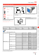
Equipment consisting of (schematic overview)
Lens page 497
Single-LED page 515
Actuator
Front bezel set page 505
Fixing nut
Each Part Number listed below includes all the black
components shown in the 3D-drawing.
To obtain a complete unit, please select the red com-
ponents from the page s shown.
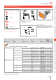
Terminal Part No.
Compo-
nent layout
Wiring
diagram
Weight
Indicator actuator round
Solder 2.8 x 0.5 mm 51-050.002F 1 0.004 kg
Solder 51-050.005F 1 0.004 kg
Universal 2.0 x 0.5 mm 51-051.006F 4 1 0.005 kg
The component layouts you will find from page 520
51