Series Series 14 Attractive. Compact. Reliable. https://eao.
14 Information about the Series Key advantages § § § § § § Attractive 22.5 mm or 30.
Index 14 Flush design Illuminated pushbutton 282 Mushroom-head pushbutton 285 Mushroom-head pushbutton illuminated 288 Selector switch 2 positions 291 Keylock switch 2 positions 294 Indicator 297 Buzzer 299 Raised design Illuminated pushbutton 300 Mushroom-head pushbutton 303 Mushroom-head pushbutton illuminated 306 Selector switch 2 positions 309 Keylock switch 2 positions 312 Indicator compact 315 Indicator full-face illumination 316 Indicator front illumination 318 Buzzer
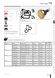
14 Flush design 01 Illuminated pushbutton, IP67 1.5 ... 6 02 Equipment consisting of (schematic overview) B 7.5 56 Ø 35 03 A 52.5 04 3 D 2 Product can differ from the current configuration. 14 Page 323 Lens Page 321 Marking Plate Page 323 Single-LED Page 325 48.5 … 71 60.5 / 68 09 Front bezel C 3 Dimensions [mm] A = Solder terminal B = Plug-in terminal 2.8 x 0.5 mm C = Universal terminal 2.0 mm x 0.5 mm Universal-Solder terminal 17 Actuator 35 min. 35 min.
Flush design 14 Component Layout Switching action Terminal Switching system Contacts Diode 1N4007 Part No. Wiring diagram Momentary Universal terminal Snap-action switching element 2 NC / 2 NO 2 14-746.0292 23 5 Maintained Universal terminal Snap-action switching element 1 NC / 1 NO 1 14-747.0292 14 5 Universal terminal Snap-action switching element 1 NC / 1 NO 2 14-748.
14 Flush design 01 Wiring diagrams 1 02 3 1 I 3 1 II 3 1 III 3 1 x2+ IV 3 1 I 3 1 II 3 1 III 3 x2+ 4 x1- IV 03 2 2 4 4 2 2 4 4 2 x1- 2 4 4 2 2 4 04 Wiring diagram 28 09 Wiring diagram 29 1 3 b+ 1 3 b+ 2 4 a- 2 4 a- 14 17 18 19 Wiring diagram 30 Wiring diagram 31 Component layouts 22 A D C 31 5.08 41 2.54 Ø1.0 (6x) 2 4 B 1 3 a b 4 2 1 7.62 1 3 a b B 45 a 4 3 B b 2 51 56 10.
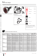
Flush design 14 Mushroom-head pushbutton, IP67 01 Equipment consisting of (schematic overview) 1.5 ... 7 7.5 Page 321 Front bezel set Page 323 Marking Plate Page 323 56 A 04 C 11 13.5 03 Ø 35 Lens 02 B 48.5 … 71 52.5 3 Dimensions [mm] A = Solder terminal B = Plug-in terminal 2.8 mm x 0.5 mm C = Universal terminal 2.0 mm x 0.5 mm Actuator 09 Product can differ from the current configuration. 14 17 50 min. Pressure ring 18 50 min.
14 Flush design 01 Wiring diagrams 02 1 b+ 2 a- 1 b+ 1 3 b+ 1 3 b+ 1 b+ 1 b+ 2 a- 2 4 a- 2 4 a- 2 a- 2 a- 03 04 Wiring diagram 5 09 1 Wiring diagram 6 3 b+ Wiring diagram 7 1 3 Wiring diagram 8 1 b+ 3 Wiring diagram 9 x2+ 1 3 Wiring diagram 10 1 b+ I I 3 x2+ 4 x1- I 14 17 18 4 2 Wiring diagram 11 1 19 3 4 2 a- 2 2 Wiring diagram 12 1 b+ I 22 a- a- 2 x1- Wiring diagram 17 3 1 I 4 4 3 2 4 x2+ 1 3 1 I 4 a- 2 Wiring
Flush design 14 Component layouts A 01 02 D C 5.08 2.54 03 Ø1.0 (6x) 2 4 B 1 3 a b 4 2 1 7.62 1 3 a b B a 4 04 3 B b 09 2 14 10.16 17 Component layout 5 Dimensions [mm] A = Terminals (rear side) B = Anti twist device C = Diode block D = Drilling plan (component side) 18 19 22 31 41 45 51 Follow us. We are on LinkedIn! 56 EAO creates possibilities. Since 1947.
14 Flush design 01 Mushroom-head pushbutton illuminated, IP67 Equipment consisting of (schematic overview) 1.5 ... 7 02 7.5 B 03 A 04 09 C 11 13.5 Product can differ from the current configuration. 14 48.5 … 71 52.5 Page 321 Front bezel set Page 323 Marking Plate Page 323 Single-LED Page 325 3 Dimensions [mm] A = Solder terminal B = Plug-in terminal 2.8 mm x 0.5 mm C = Universal terminal 2.0 mm x 0.5 mm 17 Lens Ø 35 56 Actuator 50 min. 50 min. 18 Pressure ring 19 +0.5 Ø30.
Flush design 14 Component Layout Switching action Terminal Switching system Contacts Diode 1N4007 Part No. Wiring diagram Momentary Universal terminal Snap-action switching element 1 NC / 1 NO 2 14-744.0292 15 5 Universal terminal Snap-action switching element 2 NC / 2 NO 2 14-746.0292 23 5 Universal terminal Snap-action switching element 1 NC / 1 NO 1 14-747.0292 14 5 Universal terminal Snap-action switching element 1 NC / 1 NO 2 14-748.
14 Flush design 01 Wiring diagrams 1 02 3 1 I 3 1 II 3 1 III 3 1 x2+ IV 3 1 I 3 1 II 3 1 III 3 x2+ 4 x1- IV 03 2 2 4 4 2 2 4 4 2 x1- 2 4 4 2 2 4 04 Wiring diagram 28 09 Wiring diagram 29 1 3 b+ 1 3 b+ 2 4 a- 2 4 a- 14 17 18 19 Wiring diagram 30 Wiring diagram 31 Component layouts 22 A D C 31 5.08 41 2.54 Ø1.0 (6x) 2 4 B 1 3 a b 4 2 1 7.62 1 3 a b B 45 a 4 3 B b 2 51 56 10.
Flush design 14 Selector switch 2 positions, IP67 01 Equipment consisting of (schematic overview) 1.5 ... 6 7.5 Page 323 Anti-twist device Page 326 56 A 03 Ø 35 Front bezel 02 B 15.5 04 C 2 46.5 … 69 52.5 3 Actuator Dimensions [mm] A = Solder terminal B = Plug-in terminal 2.8 x 0.5 mm C = Universal terminal 2.0 mm x 0.5 mm 09 Product can differ from the current configuration. 14 Pressure ring 17 35 min. 18 35 min.
Flush design 01 Wiring diagrams 1 02 3 1 I 3 1 I 3 1 3 4 2 4 II 03 2 2 4 4 2 04 Wiring diagram 117 09 Wiring diagram 118 Wiring diagram 119 1 3 1 3 1 3 1 3 2 4 2 4 2 4 2 4 14 17 18 Wiring diagram 120 Wiring diagram 121 1 19 Wiring diagram 122 3 1 I 3 1 I 3 Wiring diagram 123 1 II 3 1 I 3 1 II 3 III 22 2 2 4 4 2 2 4 4 2 4 2 4 31 Wiring diagram 124 41 Wiring diagram 125 1 3 1 I 3 1 II 3 Wiring diagram 126 1 III 3 IV
Flush design 14 Component layouts A 01 02 D C 5.08 2.54 03 Ø1.0 (6x) 1 3 a b 2 4 B 1 3 a b 4 2 1 7.62 B a 4 04 3 B b 09 2 14 10.16 17 Component layout 5 Dimensions [mm] A = Terminals (rear side) B = Anti twist device C = Diode block D = Drilling plan (component side) 18 19 22 31 41 45 51 56 57 61 70 71 82 84 92 96 01/2019 § eao.
14 Flush design 01 Keylock switch 2 positions, IP65 Equipment consisting of (schematic overview) 1.5 ... 6 02 7.5 B 03 A 04 Product can differ from the current configuration. 17 46.5 … 69 52.5 Anti-twist device Page 326 Actuator General information 35 min. • Lock numbers 1001, lock type KABA • Front plastic black Pressure ring 35 min. 18 Fixing nut 19 Ø30.5 +0.5 0 Each Part Number listed below includes all the black components shown in the 3D-drawing.
Flush design 14 Component Layout Switching action Terminal Switching system Contacts Switching angle Part No. Wiring diagram Rest (a) - Maintained Universal terminal Low-level element 2 NO 90° right 14-414.036K 112 5 Universal terminal Low-level element 1 NC / 1 NO 90° right 14-415.036K 111 5 Universal terminal Low-level element 2 NO 90° right 14-417.036K 112 5 Universal terminal Low-level element 1 NC / 1 NO 90° right 14-418.
14 Flush design 01 Component layouts 02 A D C 5.08 03 2.54 Ø1.0 (6x) 04 09 2 4 B 1 3 a b 4 2 1 7.62 1 3 a b B a 4 3 B b 2 14 10.16 17 18 19 Component layout 5 Dimensions [mm] A = Terminals (rear side) B = Anti twist device C = Diode block D = Drilling plan (component side) 22 31 41 45 51 56 57 61 High-intensity illuminated and robust. EAO Series 14 Indicator compact. 70 71 Ideal for safe status indications, such as of production robots – thanks to excellent visibility. .
Flush design 14 Indicator, IP67 01 Equipment consisting of (schematic overview) 1.5 ... 6 02 B Page 323 Lens Page 321 Marking Plate Page 323 56 A 04 C 2 Single-LED 03 Ø 35 Front bezel 48.5 52.5 3 09 Page 325 Dimensions [mm] A = Solder terminal B = Plug-in terminal 2.8 x 0.5 mm C = Universal terminal 2.0 mm x 0.5 mm Actuator Product can differ from the current configuration. 14 17 35 min. 35 min. 18 Pressure ring Ø30.5 19 +0.
14 Flush design 01 Component layouts 02 A D C 5.08 03 2.54 Ø1.0 (6x) 04 09 2 4 B 1 3 a b 4 2 1 7.62 1 3 a b B a 4 3 B b 2 14 10.16 17 18 19 Component layout 5 Dimensions [mm] A = Terminals (rear side) B = Anti twist device C = Diode block D = Drilling plan (component side) 22 31 41 45 51 56 57 61 70 71 82 84 92 96 298 eao.
Flush design 14 Buzzer, IP40 01 Equipment consisting of (schematic overview) 2 ... 6 02 03 Ø 35 Actuator 04 Fixing nut 46.5 2 Pressure ring Dimensions [mm] 09 Product can differ from the current configuration. 14 General information Each Part Number listed below includes all the black components shown in the 3D-drawing. 35 min. 35 min. • For PCB application use adaptor Part-No. 31942 Ø30.
14 Raised design 01 Illuminated pushbutton, IP67 1.5 ... 7 02 Equipment consisting of (schematic overview) B 7.5 45.5 A 30 03 41.5 04 3 D 14 Lens Page 321 Marking Plate Page 323 Single-LED Page 325 3 49.5/ 57 Product can differ from the current configuration. Page 323 37.5 … 60 13.5 09 Front bezel C Dimensions [mm] A = Solder terminal B = Plug-in terminal 2.8 x 0.5 mm C = Universal terminal 2.0 mm x 0.
Raised design Switching action Terminal Switching system Contacts Diode 1N4007 Part No. Wiring diagram Maintained Universal terminal Snap-action switching element 1 NC / 1 NO 2 14-748.
14 Raised design 01 Wiring diagrams 1 02 3 1 I 3 1 II 3 1 III 3 1 x2+ IV 3 1 I 3 1 II 3 1 III 3 x2+ 4 x1- IV 03 2 2 4 4 2 2 4 4 2 x1- 2 4 4 2 2 4 04 Wiring diagram 28 09 Wiring diagram 29 1 3 b+ 1 3 b+ 2 4 a- 2 4 a- 14 17 18 19 Wiring diagram 30 Wiring diagram 31 Component layouts 22 A D C 31 5.08 41 2.54 Ø1.0 (6x) 2 4 B 1 3 a b 4 2 1 7.62 1 3 a b B 45 a 4 3 B b 2 51 56 10.
Raised design 14 Mushroom-head pushbutton, IP67 01 Equipment consisting of (schematic overview) Page 321 Front bezel Page 323 Marking Plate Page 323 02 B 7.5 45.5 A 03 30 Lens 1.5 ... 7 C 13.5 28 41.5 37.5 … 60 Dimensions [mm] A = Solder terminal B = Plug-in terminal 2.8 x 0.5 mm C = Universal terminal 2.0 mm x 0.5 mm Actuator 04 3 09 Product can differ from the current configuration.
14 Raised design 01 Wiring diagrams 02 1 b+ 2 a- 1 b+ 1 3 b+ 1 3 b+ 1 b+ 1 b+ 2 a- 2 4 a- 2 4 a- 2 a- 2 a- 03 04 Wiring diagram 5 09 1 Wiring diagram 6 3 b+ Wiring diagram 7 1 3 Wiring diagram 8 1 b+ 3 Wiring diagram 9 x2+ 1 3 Wiring diagram 10 1 b+ I I 3 x2+ 4 x1- I 14 17 18 4 2 Wiring diagram 11 1 19 3 4 2 a- 2 2 Wiring diagram 12 1 b+ I 22 a- a- 2 x1- Wiring diagram 17 3 1 I 4 4 3 2 4 x2+ 1 3 1 I 4 a- 2 Wiring
Raised design 14 Component layouts A 01 02 D C 5.08 2.54 03 Ø1.0 (6x) 2 4 B 1 3 a b 4 2 1 7.62 1 3 a b B a 4 04 3 B b 09 2 14 10.16 17 Component layout 5 Dimensions [mm] A = Terminals (rear side) B = Anti twist device C = Diode block D = Drilling plan (component side) 18 19 22 31 41 45 51 Follow us. We are now on YouTube! 56 EAO ermöglicht. Seit 1947. 57 61 70 71 Come take a look at our YouTube profi le today! Be sure to give us a follow so that you can fully interact with us.
14 Raised design Mushroom-head pushbutton illuminated, IP67 1.5 ... 7 02 Equipment consisting of (schematic overview) B 7.5 45.5 03 A 41.5 04 09 Product can differ from the current configuration. 14 3 D 13.5 28 Lens Page 321 Front bezel Page 323 Marking Plate Page 323 Single-LED Page 325 C 30 01 37.5 … 60 49.5/ 57 3 Dimensions [mm] A = Solder terminal B = Plug-in terminal 2.8 x 0.5 mm C = Universal terminal 2.0 mm x 0.
Raised design Switching action Terminal Switching system Contacts Diode 1N4007 Part No. Wiring diagram Maintained Universal terminal Snap-action switching element 1 NC / 1 NO 2 14-748.
14 Raised design 01 Wiring diagrams 1 02 3 1 I 3 1 II 3 1 III 3 1 x2+ IV 3 1 I 3 1 II 3 1 III 3 x2+ 4 x1- IV 03 2 2 4 4 2 2 4 4 2 x1- 2 4 4 2 2 4 04 Wiring diagram 28 09 Wiring diagram 29 1 3 b+ 1 3 b+ 2 4 a- 2 4 a- 14 17 18 19 Wiring diagram 30 Wiring diagram 31 Component layouts 22 A D C 31 5.08 41 2.54 Ø1.0 (6x) 2 4 B 1 3 a b 4 2 1 7.62 1 3 a b B 45 a 4 3 B b 2 51 56 10.
Raised design 14 Selector switch 2 positions, IP67 01 Equipment consisting of (schematic overview) 1.5 ... 7 7.5 02 B 45.5 03 25 A 30 Front bezel Actuator 04 C 13.5 35.5 … 58 27 41.5 3 Dimensions [mm] A = Solder terminal B = Plug-in terminal 2.8 x 0.5 mm C = Universal terminal 2.0 mm x 0.5 mm 14 Fixing nut NJO Each Part Number listed below includes all the black components shown in the 3D-drawing. NJO 09 Product can differ from the current configuration.
14 Raised design 01 Wiring diagrams 1 02 3 1 I 3 1 I 3 1 3 4 2 4 II 03 2 2 4 2 4 04 Wiring diagram 117 09 Wiring diagram 118 Wiring diagram 119 1 3 1 3 1 3 1 3 2 4 2 4 2 4 2 4 14 17 18 Wiring diagram 120 Wiring diagram 121 1 19 Wiring diagram 122 3 1 I 3 1 I Wiring diagram 123 3 1 II 3 1 I 3 1 II 3 III 22 2 2 4 4 2 2 4 2 4 2 4 4 31 Wiring diagram 124 41 Wiring diagram 125 1 3 1 I 3 1 3 II Wiring diagram 126 1 III 3 IV
Raised design 14 Component layouts A 01 02 D C 5.08 2.54 03 Ø1.0 (6x) 1 3 a b 2 4 B 1 3 a b 4 2 1 7.62 B a 4 04 3 B b 09 2 14 10.16 17 Component layout 5 Dimensions [mm] A = Terminals (rear side) B = Anti twist device C = Diode block D = Drilling plan (component side) 18 19 22 31 41 45 51 56 57 61 70 71 82 84 92 96 01/2019 § eao.
14 Raised design 01 Keylock switch 2 positions, IP65 Equipment consisting of (schematic overview) 1.5 ... 7 02 B 7.5 45.5 03 04 35.5 … 58 41.5 3 Actuator Product can differ from the current configuration. Dimensions [mm] A = Solder terminal B = Plug-in terminal 2.8 mm x 0.5 mm C = Universal terminal 2.0 mm x 0.
Raised design 14 Component Layout Switching action Terminal Switching system Contacts Switching angle Part No. Wiring diagram Rest (a) - Maintained Universal terminal Low-level element 1 NC / 1 NO 90° right 14-415.036K 111 5 Rest - Maintained (a) Universal terminal Low-level element 2 NO 90° right 14-417.036K 112 5 Universal terminal Low-level element 1 NC / 1 NO 90° right 14-418.036K 111 5 Universal terminal Low-level element 2 NO 42° right 14-437.
14 Raised design 01 Component layouts 02 A D C 5.08 03 2.54 Ø1.0 (6x) 04 09 2 4 B 1 3 a b 4 2 1 7.62 1 3 a b B a 4 3 B b 2 14 10.16 17 18 19 Component layout 5 Dimensions [mm] A = Terminals (rear side) B = Anti twist device C = Diode block D = Drilling plan (component side) 22 31 41 45 51 56 57 61 High-intensity illuminated and robust. EAO Series 14 Indicator compact. 70 71 Ideal for safe status indications – thanks to excellent visibility. . High-intensity illumination .
Raised design 14 Indicator compact, IP65, IP67, IP69K 01 Equipment consisting of (schematic overview) Indicator . Y 02 03 Fixing nut 04 Each Part Number listed below includes all the black components shown in the 3D-drawing. Dimensions [mm] 09 Product can differ from the current configuration.
14 Raised design 01 Indicator full-face illumination, IP67 Equipment consisting of (schematic overview) 1.5 ... 7 02 B 34 03 30 A 3 Marking cap Page 323 Single-LED Page 325 D 13.5 09 Page 322 C 41.5 04 Lens cap Product can differ from the current configuration. 30 3 41.5 Dimensions [mm] A = Solder terminal B = Plug-in terminal 2.8 x 0.5 mm C = Universal terminal 2.0 mm x 0.
Raised design 14 Component layouts A 01 02 D C 5.08 2.54 03 Ø1.0 (6x) 1 3 a b 2 4 B 1 3 a b 4 2 1 7.62 B a 4 04 3 B b 09 2 14 10.16 17 Component layout 5 Dimensions [mm] A = Terminals (rear side) B = Anti twist device C = Diode block D = Drilling plan (component side) 18 19 22 31 41 45 51 56 57 61 70 71 82 84 92 96 01/2019 § eao.
14 Raised design Indicator front illumination, IP67 Equipment consisting of (schematic overview) 1.5 ... 7 02 B 45.5 03 A Page 323 Lens Page 321 Marking Plate Page 323 Single-LED Page 325 C 04 13.5 09 Front bezel 30 01 Product can differ from the current configuration. 14 17 37.5 41.5 3 Dimensions [mm] A = Solder terminal B = Plug-in terminal 2.8 x 0.5 mm C = Universal terminal 2.0 mm x 0.
Raised design 14 Component layouts A 01 02 D C 5.08 2.54 03 Ø1.0 (6x) 2 4 B 1 3 a b 4 2 1 7.62 1 3 a b B a 4 04 3 B b 09 2 14 10.16 17 Component layout 5 Dimensions [mm] A = Terminals (rear side) B = Anti twist device C = Diode block D = Drilling plan (component side) 18 19 22 31 41 45 51 Follow us. We are on LinkedIn! 56 EAO creates possibilities. Since 1947.
14 Raised design 01 Buzzer, IP65 Equipment consisting of (schematic overview) 2 ... 6 02 Actuator 30 03 04 13.5 17 Product can differ from the current configuration. Dimensions [mm] Each Part Number listed below includes all the black components shown in the 3D-drawing. General information NJO • For PCB application use adaptor Part-No. 31942 18 14 Fixing nut NJO 09 35.
Components 14 01 02 Lens plastic Lens material Lens colour Lens optics Lens shape Lens illumination Dimensions Part No. Plastic Black opaque flush non illuminative Symbol Ø 23.7 mm 704.602.0 Red transparent flush illuminative Ø 23,7 mm 704.602.2 Yellow transparent flush illuminative Ø 23,7 mm 704.602.4 Green transparent flush illuminative Ø 23,7 mm 704.602.5 Blue transparent flush illuminative Ø 23,7 mm 704.602.
14 Components 01 Lens metal round spot round 02 03 Lens material Lens colour Lens optics Lens shape Lens illumination Dimensions Part No. Aluminium Black opaque flush illuminative Ø 23,7 mm 704.601.01 Red opaque flush illuminative Ø 23,7 mm 704.601.21 Gold opaque flush illuminative Ø 23,7 mm 704.601.41 Olive green opaque flush illuminative Ø 23,7 mm 704.601.51 Blue opaque flush illuminative Ø 23,7 mm 704.601.61 Nature opaque flush illuminative Ø 23,7 mm 704.601.
Components 14 01 Marking cap for front illumination 02 Marking cap material Marking cap colour Marking cap optics Dimensions Marking cap surface Part No. Plastic Colourless transparent Ø 29 mm ribbed 704.610.7 White translucent Ø 29 mm 03 704.610.9 04 09 Marking cap for full face illumination Marking cap material Marking cap colour Marking cap optics Dimensions Marking cap surface Part No. Plastic Colourless transparent Ø 29 mm ribbed 704.608.
14 Components 01 Front bezel set protective membrane 02 03 04 09 Product attributes Front bezel material Front bezel colour Front bezel surface Mounting cut-out Dimensions Part No. With transparent silicone membrane Aluminium Nature anodised Ø 30.5 mm Ø 35 mm 14-955.3 Aluminium Black anodised Ø 30.5 mm Ø 35 mm 14-955.4 Stainless steel Nature Ø 30.5 mm Ø 35 mm 14-955.
Components 14 01 Single-LED, T5.7 Illumination colour Operating voltage Operation current Lumi. Intensity Dom. Wavelength Part No. Wiring diagram Red 6 V DC +10% 15 mA ±15 % 350 mcd 630 nm 10-2106.3142 33 12 V AC/DC +10% 7 - 14 mA ±15 % 330 mcd 630 nm 10-2109.1062 33 24 V AC/DC +10% 7 - 14 mA ±15 % 330 mcd 630 nm 10-2112.1062 33 28 V AC/DC +10% 7 - 14 mA ±15 % 330 mcd 630 nm 10-2113.1062 33 48 V AC/DC +10% 4 - 8 mA ±15 % 200 mcd 630 nm 10-2119.
14 Components 01 Wiring diagrams 02 03 04 Wiring diagram 33 09 14 17 18 19 22 Filament lamp Operating voltage Operation current Part No. Wiring diagram 6 V AC/DC 200 mA 10-1106.1369 34 12 V AC/DC 100 mA 10-1109.1329 34 24 V AC/DC 50 mA 10-1112.1279 34 28 V AC/DC 40 mA 10-1113.1249 34 30 V AC/DC 40 mA 10-1114.1249 34 36 V AC/DC 35 mA 10-1116.1229 34 48 V AC/DC 25 mA 10-1119.1199 34 31max. Ø 5.4 max. 31 41 6.5max. 22max.
Accessories 14 Front side 01 02 03 04 Legend frame Product attributes Dimensions Material Colour Surface Mounting type Part No. For raised design 30 mm x 0.75 mm x 50 mm aluminium Black anodised adhesive 704.968.2 For flush design 35 mm x 0.75 mm x 57.5 mm aluminium Black anodised adhesive 704.968.3 09 14 Additional information • The colour of anodised aluminium parts can vary due to technical production reasons 0.75 4 14.5 18 0.75 19 Ø 30.6 40 57.5 4 14.5 23.5 Ø22.
14 Accessories 01 Material Colour Mounting cut-out Part No. Ø 28 mm plastic Black Ø 22.3 mm 704.960.4 Ø 36 mm plastic Black Ø 30.5 mm 704.964.8 Additional information • Please note that bigger minimum distances are necessary 09 4.8 Ø 28 14 2.6 20 17 2.5 ... 6 14 Ø 35.6 04 Dimensions Ø 36.2 03 Blind plug Ø 30 02 2…6 18 19 Dimensions [mm] for Part No. 704.960.4 22 31 Dimensions [mm] for Part No. 704.964.8 Spare key Product attributes Part No.
Accessories 14 01 Protective cover raised design Product attributes Material Optics Part No. For pushbutton plastic transparent 704.925.0 For pushbutton, with spring fitted plastic transparent 704.925.3 For selector switch plastic transparent 704.925.2 02 03 04 Additional information • Hinged, with means for sealing 44 09 30 44 14 18 37 1.
14 Accessories 01 Rear side 02 03 04 Flat receptacle Product attributes Material Part No. 2.0 x 0.5 mm plug-in terminal metal 31-945 2.8 x 0.8 mm plug-in terminal metal 31-946 Product attributes Material Part No. For flat receptacle 2.0 mm plastic 31-928 For flat receptacle 2.8 mm plastic 31-929 Cover plug-in terminals for snap-action switching element 2.8 mm plastic 01-928 Product attributes Material Part No.
Accessories 14 Component layouts 01 02 A B C 03 17.9 31 31 a b a 24 14 4 9 42 09 9 b 04 17.9 17.9 17.9 9.6 17 3 b F 4 3 1 2 a b 2 3 1 4 a 18 D Ø1.0 (4x) 19 15.24 Ø1.0 (6x) 1.27 5 x 2.54 1.27 1.27 0.85 1.27 22 7.62 E 31 Component layout 2 41 Dimensions [mm] A = Socket 90° angled B = Occupancy plan (component side) C = Diode block D = Drilling plan (component side) E = Non-metallic F = Extendable mounting pins 45 51 A 56 B C 57 7.62 7.62 Ø1.0 (6x) 12.
14 Accessories 01 02 Component layouts A B 03 7.62 Ø1.0 04 3 4 7.62 2 1 10.16 7.62 09 C b a 14 Ø1.0 (6x) Ø2.1 D 17 18 Component layout 4 Dimensions [mm] A = Axial socket B = Drilling-/occupancy plan (component side) C = Non-metallic D = For central mounting with M2 screw, if desired 19 22 31 41 45 51 Series resistor Operating voltage Resistance Part No. 110 V AC 2.7 kOhm 02-904.0 125 V AC 3.3 kOhm 02-904.1 145 V AC 4.7 kOhm 02-904.3 240 V AC 10 kOhm 02-904.
Accessories 14 Mounting 01 02 03 Enclosure Product attributes Dimensions Material Colour IP Protection Part No. With mounting cut-out 1 x Ø 22.5 mm, with anti-twist device 94 mm x 81 mm x 94 mm plastic Grey IP66 704.945.1 With mounting cut-out 2 x Ø 22.3 mm, with anti-twist device 130 mm x 81 mm x 94 mm plastic Grey IP66 704.945.2 With mounting cut-out 3 x Ø 22.3 mm, with anti-twist device 180 mm x 81 mm x 94 mm plastic Grey IP66 704.945.3 With mounting cut-out 4 x Ø 22.
14 Accessories 01 02 Reducing ring Material Colour Surface Part No. 03 Aluminium Black anodised 704.960.0 Nature anodised 704.960.8 04 Additional information • Devices Ø 22.3 mm in mounting cut-out Ø 30.5 mm • The colour of anodised aluminium parts can vary due to technical production reasons 14 Ø 30.4 17 Ø22.6 2 Ø 35 09 18 2.8 19 22 Dimensions [mm] 31 41 45 51 56 57 61 70 71 82 84 92 96 334 eao.
Technical data 14 Actuator with snap-action switching element Switching system 01 02 Actuating travel Illuminated pushbutton approx. 3 mm Self-cleaning, double-break, snap action switching system (with contact gap 2 mm x 0.5 mm). 1 normally closed or 1 normally open contact per element. Snap-action switching elements with soldering terminals at the sides: up to 4 switching element can be on a pushbutton (max. 4 normally closed and 4 normally open contacts).
14 Technical data 01 02 03 04 09 14 Protection degree Climate resistance As per DIN EN 60529 IP67 front side, Indicator IP67 front side, Illuminated pushbutton IP67 front side, Mushroom-head pushbutton IP67 front side, Selector switch IP65 front side, Keylock switch Damp heat state as per DIN EN 60068-2-78 Damp heat cyclic as per DIN EN 60068-2-30 Approvals Approbations Vibration resistance CB (IEC 61058-1) CSA CQC ENEC (EN 61058-1) DNV GL (previously Germanischer Lloyd) UL (sinusoidal) Max.
Technical data Electrical characteristics Protection degree 100 mA at 42 VAC / VDC As per EN IEC 60529 IP67 front side, Indicator IP67 front side, Illuminated pushbutton IP67 front side, Mushroom-head pushbutton IP67 front side, Selector switch IP65 front side, Keylock switch Electric strength Shock resistance 3000 VAC, 50 Hz, 1 min. between all terminals and earth, as per EN IEC 61058-1-15 (semi-sinusoidal) Max.
14 Technical data 01 Approvals Approbations 02 CQC EMC 03 Conformities 04 CE 2014 / 30 / EC (EMC) 2011 / 65 / EC (RoHS) 09 14 17 18 Indicator compact Material Electrical characteristics Lens cap Operation Voltage Plastic 24 VAC / DC (14…32 VAC / DC) Housing Operating current 19 Plastic < 50 mA 22 Mechanical characteristics 31 Iifetime 50 000 h Terminals PIT push-in terminal Skinning 8 mm Wire cross-section: Wire 0.2 to 1.0 mm² Stranded wire 0.2 to 1.
Marking 14 General notes 01 1. Engraving 2. Hot stamping In addition to the most commonly used world languages, in DIN1451-3 close spacing, other typefaces are available as Scandinavian, Slavic, Greek, Russian and Polish. Red, blue and black lenses are filled with white colour. Other colour lenses are filled in black. Standard height of letters is 3 mm. If the height is not specified, we will supply 3 mm engraved letters. For larger series it is worth considering markings by means of hot stamping.
14 Marking 01 Engraving marking plate for Indicator and illuminated Pushbutton round, front illumination All dimensions in mm 02 03 Height of marking plate Height of letters h Marking plate (Ø 20) Number of lines Number of capital letters per line (guide value) Number of lowercase letters per line (guide value) Picture 3 3 6-8 7-9 B1 4 3 5-6 6-7 B1 04 8 3 – – B1 3 2 6 7 B2 09 4 2 5 6 B2 8 2 1 2 B2 3 1 8 9 B3 14 4 1 6 7 B3 8 1 3 3 B3 Number of lowerca
Marking 14 Standard texts for marking plates and marking caps for Indicator and Illuminated Pushbutton 01 Height of letters 6 mm I Part No. 704.609.912001 II Part No. 704.609.912002 III Part No. 704.609.912003 O Part No. 704.609.912004 02 03 EIN Part No. 704.609.912005 AUS Part No. 704.609.912006 AUF Part No. 704.609.912007 AB Part No. 704.609.912008 04 START Part No. 704.609.912009 STOP Part No. 704.609.912010 HAND Part No. 704.609.912011 AUTO Part No. 704.609.
14 Marking 01 Symbols for marking plates and marking caps for Indicator and Illuminated Pushbutton All marking plates with the printed article-numbers are available for flat lenses, marking cap only on request. 02 03 04 Part No. 704.609.910001 Direction of linear rectilinear motion (also for ) Part No. 704.609.910002 Linear motion in 2 directions (also for ) Part No. 704.609.910004 Limited linear motion (also for ) Part No. 704.609.910007 Direction of continuous rotation (right) Part No. 704.609.
Application guidelines 14 Suppressor circuits 01 When switching inductive loads such as relays, DC motors, and DC solenoids, it is always important to absorb surges (e. g. with a diode) to protect the contacts. When these inductive loads are switched off, a counter emf can severely damage switch contacts and greatly shorten lifetime. Fig. 1 shows an inductive load with a free-wheeling diode connected in parallel.