
Datasheet


Indicator 6 mm LED 3 mm, IP67
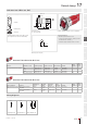
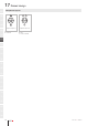
Equipment consisting of (schematic overview)
Actuator
Retainingring
Fixing nut
Each Part Number listed below includes all the
black components shown in the 3D-drawing.
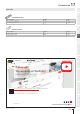
Dimensions [mm]
A = Protection tube
Product can differ from the current conguration.
Mounting cut-outs [mm]
General information
• Maximum panel thickness 6 mm
• Connectors: Brass terminal = anode (+); brass
tinned terminal = cathode (-)
• Terminal: Plug-interminal 2.8 mm x 0.8 mm
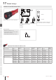
Actuator, Front dimension Ø 25 mm
Reflector Illumination colour Operating voltage Operation current Lumi. Intensity Part No.
Wiring
diagram
Com-
ponent
Layout
Metal, polished chromium-plated Red 24 V DC ±10 % 19 mA ±15 % 160 mcd 17-530350 70 11
Green 24 V DC ±10 % 19 mA ±15 % 120 mcd 17-530351 70 11
Yellow 24 V DC ±10 % 19 mA ±15 % 350 mcd 17-530352 70 11
Red / Yellow / Green 24 V DC ±10 % 24 - 50 mA ±15 % 51/92/120 mcd 17-540354 128 12
Actuator, Front dimension Ø 25 mm
Product attributes Reflector
Illumination
colour
Operating
voltage
Operation
current
Lumi.
Intensity Part No.
Wiring
diagram
Com-
ponent
Layout
With terminals protection
tube
Metal, polished chromi-
um-plated
Green 230 V AC
±10 %
4 mA ±15 % 20 mcd 17-570231 55 11
Metal, polished chromi-
um-plated
Yellow 230 V AC
±10 %
4 mA ±15 % 48 mcd 17-570232 55 11
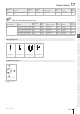
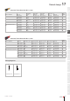
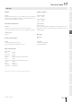
Wiring diagrams
Wiring diagram 55 Wiring diagram 70 Wiring diagram 128
Raised design
01/2019 § eao.com
359
17
01
02
03
04
09
14
17
18
19
22
31
41
45
51
56
57
61
70
71
82
84
92
96
58
12
9
4.5
M22 x 1.5
SW27
183
A
Ø22.3
+
0.4
0
x2+
x1-
x2+
x1-
x3+x2+
x1-