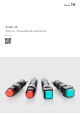
Series Series 19 Proven. Streamlined and tactile. https://eao.
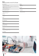
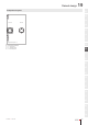
19 Information about the Series Key advantages Markings Excellent tactile feedback Gold-plated silver contacts available for low voltages and currents § Bright, homogenous illumination § Compact construction § Can be mounted on PCBs § § Typical application areas Conformities § § § § § Audio / video Measurement technology Medical engineering Engraving Film insert Approvals § § § No approbations CE 2011/65/EU (RoHS) Functions § § Illuminated pushbutton Indicator Design § Raised IP front prot
Index 19 Raised design Illuminated pushbutton square 410 Illuminated pushbutton round 412 Indicator square 414 Indicator round 416 Components 418 Accessories 420 Technical data 423 Application guidelines 425 01 02 03 04 09 14 17 18 19 22 31 41 45 51 56 57 61 70 71 82 84 92 96 01/2019 § eao.
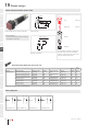
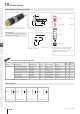
19 Raised design Illuminated pushbutton square, IP40 Equipment consisting of (schematic overview) 02 8 max. 1 03 17 Page 418 9 Single-LED Page 418 Product can differ from the current configuration. 33 Dimensions [mm] General information NJO • For LED element fitting information see Application guidelines, LED polarity Actuator Y ± NJO 14 Lens 5.
Raised design 19 Component layouts 01 02 A B 03 9 x 9 mm Ø9 mm 04 1 X– Y+ X 1 X– Y+ 09 X 14 C D 17 E Component layout 17 18 A = Terminals (rear side) B = Illuminated pushbutton C = x = Contact no. D = 2 = Normally open E = 4 = Normally close 19 22 31 41 45 51 56 57 61 70 71 82 84 92 96 01/2019 § eao.
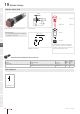
19 Raised design Illuminated pushbutton round, IP40 Equipment consisting of (schematic overview) 02 8 max. 1 03 17 Page 418 9 Product can differ from the current configuration. 33 Single-LED Page 418 Dimensions [mm] General information NJO • For LED element fitting information see Application guidelines, LED polarity Y ± Actuator NJO 14 Lens 5.
Raised design 19 Component layouts 01 02 A B 03 9 x 9 mm Ø9 mm 04 1 X– Y+ 1 X X– Y+ 09 X 14 C D 17 E Component layout 17 18 A = Terminals (rear side) B = Illuminated pushbutton C = x = Contact no. D = 2 = Normally open E = 4 = Normally close 19 22 31 41 45 51 EAO Downloads. www.eao.com/downloads 56 EAO creates possibilities. Since 1947. 57 61 70 71 On our website you can download technical data, assembly instructions, catalogs, brochures and much more. 82 84 92 www.eao.
19 Raised design 01 Indicator square, IP40 Equipment consisting of (schematic overview) 02 8 max. Ø9 03 17 9 Product can differ from the current configuration. L Single-LED Page 418 Dimensions [mm] General information NJO • For LED element fitting information see Application guidelines, LED polarity Y ± Actuator NJO 14 Page 418 5.8 04 09 Lens 18 Fixing nut ± 19 Each Part Number listed below includes all the black components shown in the 3D-drawing.
Raised design 19 Component layouts 01 02 A B 03 9 x 9 mm Y+ X– 04 Ø 9 mm 09 Y+ X– 14 Component layout 16 17 A = Terminals (rear side) B = Indicator 18 19 22 31 41 45 51 56 57 61 70 71 82 84 92 96 01/2019 § eao.
19 Raised design 01 Indicator round, IP40 Equipment consisting of (schematic overview) 02 8 max. Ø9 03 17 9 Product can differ from the current configuration. L Single-LED Page 418 Dimensions [mm] General information NJO • For LED element fitting information see Application guidelines, LED polarity Y ± Actuator NJO 14 Page 418 5.8 04 09 Lens 18 Fixing nut ± 19 Each Part Number listed below includes all the black components shown in the 3D-drawing.
Raised design 19 Component layouts 01 02 A B 03 9 x 9 mm Y+ X– 04 Ø 9 mm 09 Y+ X– 14 Component layout 16 17 A = Terminals (rear side) B = Indicator 18 19 22 31 41 45 51 56 57 61 70 71 82 84 92 96 01/2019 § eao.
19 Components 01 Lens 02 Product attributes Lens material Lens colour Lens optics Lens shape Lens illumination Dimensions Part No. For film insert Plastic Red transparent flush illuminative 7.3 mm x 7.3 mm 19-951.2 Plastic Yellow transparent flush illuminative 7.3 mm x 7.3 mm 19-951.4 Plastic Green transparent flush illuminative 7.3 mm x 7.3 mm 19-951.5 Plastic Blue transparent flush illuminative 7.3 mm x 7.3 mm 19-951.
Components 19 Wiring diagrams 01 x+ 02 03 y- 04 Wiring diagram 145 09 14 Single-LED,T1 Bi-Pin Illumination colour Operating voltage Operation current Lumi. Intensity Dom. Wavelength Part No. Wiring diagram Red 28 V AC/DC +10% 5 - 9 mA ±15 % 45 mcd 625 nm 10-2613.1072 146 Yellow 28 V AC/DC +10% 5 - 9 mA ±15 % 270 mcd 580 nm 10-2613.1074 146 Green 28 V AC/DC +10% 5 - 9 mA ±15 % 320 mcd 525 nm 10-2613.
19 Accessories 01 Front side 02 03 04 Blind plug Dimensions Material Colour Mounting cut-out Part No. 9 mm x 9 mm plastic Black Ø 8 mm 19-948.0 Ø 9 mm plastic Black Ø 8 mm 19-949.0 09 14 17 18 19 22 31 41 45 51 Follow us. We are on LinkedIn! 56 EAO creates possibilities. Since 1947. 57 61 70 71 Come take a look at our LinkedIn profi le today! Be sure to give us a follow so that you can fully interact with us. 82 https://www.linkedin.com/company/eao/ 84 92 www.eao.
Accessories 19 Rear side 01 02 Flat receptacle Product attributes Material Part No. 2.0 x 0.5 mm plug-in terminal metal 31-945 03 04 09 Insulation sleeve Product attributes Material Part No. For flat receptacle 2.0 mm plastic 31-928 14 17 PCB plug-in base 18 Dimensions Terminal Pins Part No. Component Layout 8.9 mm x 11.7 mm x 8.9 mm PCB terminal Axial 19-940 4 8.9 mm x 11.7 mm x 8.9 mm PCB terminal 90° angled 19-941 3 19 22 11.7 3.2 8.9 41 5.6 8.9 8.9 31 11.7 3.
19 Accessories 01 Mounting 02 Fixing nut 03 04 Dimensions Material Thread Part No. Ø 9 mm metal M8 x 13 mm 19-991 09 14 Lens remover Material Part No. metal 19-910 17 Lamp remover 18 19 Product attributes Material Part No. A switching action may occur when replacing the lamp plastic 11-906 Product attributes Material Part No. For fixing nut long Part No. 19-991 metal 19-905 Product attributes Material Part No.
Technical data 19 Actuator with snap-action switching element 01 Switching system Electrical characteristics Single-break, snap-action switching system 1 normally open contact Switching voltage and switching current 02 03 Silver plated: Max. 50 VAC, 0.8 A / 72 VDC, 0.7 A Min. 20 V, 10 mA 04 Material Gold plated Silver, Silver plated Gold plated: Max. 50 VAC, 100 mA / 72 VDC, 70 mA Min.
19 Technical data 01 Actuator with low-level switching element Switching system Electrical characteristics 03 This low-level switching system was developed for low switching voltages and currents. Switching voltage and switching current 04 Single-break momentary contact, as normally open or normally closed with 4 independent points of contact. Electric strength 09 1 normally open or 1 normally closed contact.
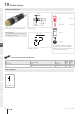
Application guidelines 19 Suppressor circuits 01 When switching inductive loads such as relays, DC motors, and DC solenoids, it is always important to absorb surges (e. g. with a diode) to protect the contacts. When these inductive loads are switched off, a counter emf can severely damage switch contacts and greatly shorten lifetime. Fig. 1 shows an inductive load with a free-wheeling diode connected in parallel.