
Datasheet

Illuminated pushbutton round, IP40
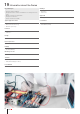
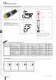
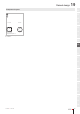
Equipment consisting of (schematic overview)
Lens Page 418
Single-LED Page 418
Actuator
Fixing nut
Each Part Number listed below includes all the
black components shown in the 3D-drawing.
To obtain a complete unit, please select the red
components from the pages shown.
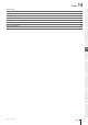
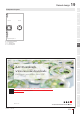
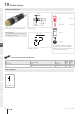
Dimensions [mm]
Product can differ from the current conguration.
Mounting cut-outs [mm]
General information
• For LED element tting information see Applica-
tion guidelines, LED polarity
Actuator, Front dimension Ø 9 mm
Terminal Switching system Switching action Contacts Contact material Part No.
Wiring
diagram
Com-
ponent
Layout
Plug-interminal Snap-action switching element Momentary 1 NO Silver 19-139.015 143 17
Snap-action switching element Momentary 1 NO Gold-plated silver 19-139.035 143 17
Snap-action switching element Maintained 1 NO Silver 19-279.015 144 17
Snap-action switching element Maintained 1 NO Gold-plated silver 19-279.035 144 17
Low-level element Momentary 1 NO Gold-plated silver 19-431.035 143 17
Low-level element Momentary 1 NC Gold-plated silver 19-432.035 141 17
Low-level element Maintained 1 NO Gold-plated silver 19-471.035 144 17
Low-level element Maintained 1 NC Gold-plated silver 19-472.035 142 17
Contacts: NC = Normally closed, NO = Normally open
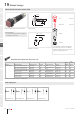
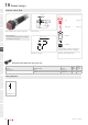
Wiring diagrams
Wiring diagram 141 Wiring diagram 142
Wiring diagram 143
Wiring diagram 144
Raised design
eao.com § 01/2019
412
19
01
02
03
04
09
14
17
18
19
22
31
41
45
51
56
57
61
70
71
82
84
92
96
339
8 max.
5.8
1
Ø9
NJO
Y±
NJO
±
3
1
X+
Y-
1
3
Y-
X+
3
1
X+
Y-
1
Y-
3
X+