
Datasheet


31
Geräte erhabener Einbau
6
02.2008
Benötigtes Zubehör:
d Druckhaube Kunststoff Seite 8
d Single-LED Seite 11
Fortsetzung nächste Seite
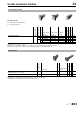
Diode (1N 4007): D = Diode, - = keine
Anschlüsse: U = Universalanschluss, L = Lötanschluss, L1 = Lötanschluss (auch steckbar 2,8 x 0,5 mm)
Bauteilelayout ab Seite 19, Lochbild ab Seite 20, Massbild ab Seite 20, Schaltbild ab Seite 22
Fortsetzung nächste Seite
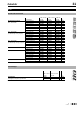
Weitere Angaben in den Technischen Daten und Anwendungsbeispielen
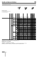
Anschlüsse: L1 = Lötanschluss (auch steckbar 2,8 x 0,5 mm), L = Lötanschluss
Lochbild ab Seite 20, Massbild ab Seite 20, Schaltbild ab Seite 22
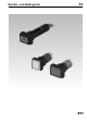
Leuchtmelder-Vorsatz
Frontschutzart
Diode (1N 4007)
Anschlüsse
b 18 x 18 mm
Typ-Nr.
a 18 x 24 mm
Typ-Nr.
Ø 18 mm
Typ-Nr.
Bauteilelayout
Lochbild
Massbild
Schaltbild
e
Leuchtmelder-Vorsatz IP 40 1 D U 31-703.006 31-701.006 4 1 5 33 0.006
2 D U 31-704.006 31-702.006 4 1 5 34 0.006
-L31-050.005 31-040.005 31-030.005 144 0.004
L1 31-050.002 31-040.002 31-030.002 143 0.004
U 31-051.006 31-041.006 31-031.006 4153 0.005
Alarmsummer
Frontschutzart
Frontkappe
Anschlüsse
a 18 x 24 mm
Typ-Nr.
Lochbild
Massbild
Schaltbild
e
Alarmsummer
Betriebsspannung : 10 ... 26 VDC
IP 40 Kunststoff schwarz L1 31-801.002 1710.015
Betriebsspannung : 10 ... 55 VAC, 10 ... 75 VDC IP 40 Kunststoff schwarz L 31-810.005 1820.015