EAO – Your Expert Partner for Human Machine Interfaces EAO Product Information Series 44
Switches and Indicators 44
Contents 44 Description ...................................................................................................... 3 Product Assembly .......................................................................................... 4 Mounting instruction ...................................................................................... 5 Devices complete, raised mounting.............................................................. 6 Devices raised mounting ...................................
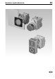
44 Description Product Information General notes Series 44, a modular system of control units, offers the user numerous combinations with its wide range of actuator elements for pushbuttons, emergency-stop pushbuttons, rotary and keylock switches, interlocking pushbuttons, potentiometer drives, illuminated pushbuttons and indicators. At the front the actuators feature an IP 65 protection class and can be supplied with mat grey or mat chrome front rings.
44 Product Assembly Illuminated pushbutton, front mounting, raised mounting 1 2 3 4 5 6 7 8 0 Actuator Label for Label support Label support Fixing nut Front adapter Lamp element Switching element 1. level Switching element 2. level Illuminated pushbutton, front mounting, flush mounting 1 2 3 4 5 6 7 8 0 Actuator Front bezel set flush mounting Front panel Fixing nut Front adapter Lamp element Switching element 1. level Switching element 2.
44 Mounting instruction Dismantling function elements To dismantle switching element, lamp element or lamp transformer, slightly lift the latching arm with the tip of a screwdriver.
44 Devices complete, raised mounting Indicator full-face illumination complete Essential Accessories: d Single-LED page 45 Technical drawing Circuit drawing e 1 1 1 1 13 13 13 13 3 3 3 3 0.025 0.025 0.025 0.025 Circuit drawing Ø 28 mm Typ-Nr. 44-750.27.000 44-750.25.000 44-750.22.000 44-750.24.
44 Devices complete, raised mounting Pushbutton complete MA M Lens Plastic black Plastic green Plastic red Plastic black Plastic green Plastic white Plastic yellow Ø 28 mm Typ-Nr. 44-702.20.100 44-702.25.010 44-701.22.001 44-701.20.100 44-701.25.010 44-701.29.010 44-701.24.
44 Devices complete, raised mounting Emergency-stop pusbutton, foolproof EN IEC 60947-5-5, complete Application as per DIN EN ISO 13850 and EN 60204-1 MA 1 NC IP 65 ST MA 1 NC Plastic red 44-712.001 Circuit drawing Contacts ST Ø 37 mm Typ-Nr. 44-713.
44 Devices complete, raised mounting Key lock switch 2 positions complete MA 0 0+I Ø 28 mm Typ-Nr. 44-730.21.100 44-730.22.100 Circuit drawing ST Front ring Plastic matt-chrome Plastic matt-chrome Technical drawing Switching action Key lock switch 2 positions complete Position 0 : Basic position Position I : Maintained action Standard lock 9500 Contacts 1 NC + 1 NO Mounting dimensions Terminals IP 65 0 Key remove Front protection Continuation see next page e 1 1 18 18 33 33 0.075 0.
44 Devices complete, raised mounting Selector switch 2 positions complete ST MA Lever Plastic black Front ring Plastic matt-chrome Ø 28 mm Typ-Nr. 44-720.20.100 Circuit drawing Switching action Selector switch 2 positions complete Position 0 : Basic position Position I : Maintained action Contacts 1 NC + 1 NO Technical drawing Terminals IP 65 0 Mounting dimensions Front protection Continuation see next page e 1 16 17 0.
44 Devices complete, raised mounting Control switch IP 65 IP 65 S1 S1 M M 4 NC + 4 NO 4 NC + 4 NO Plastic black Plastic black 44-800.4 44-800.8 Circuit drawing M Technical drawing S1 Ø 22 mm Typ-Nr. 44-800.
44 Devices raised mounting Indicator actuator full-face illumination Essential Accessories: d Front adapter, front mounting page 42 d d Lamp element, front mounting page 43 Single-LED page 45 IP 65 Plastic matt-grey Mounting dimensions from page 58, Technical drawing from page 59 12 03.2009 Lens Plastic blue Plastic colourless Plastic green Plastic red Plastic yellow Plastic blue Plastic colourless Plastic green Plastic red Plastic yellow Ø 28 mm Typ-Nr. 44-750.26 44-750.27 44-750.25 44-750.
44 Devices raised mounting Indicator actuator front illumination Essential Accessories: d Base adaptor page 43 d d d Front adapter, front mounting page 42 Lamp element, front mounting page 43 Single-LED page 45 IP 65 Plastic matt-grey Lens Plastic blue Plastic green Plastic red Plastic white Plastic yellow Plastic blue Plastic green Plastic red Plastic white Plastic yellow Ø 28 mm Typ-Nr. 44-751.26 44-751.25 44-751.22 44-751.29 44-751.24 44-751.66 44-751.65 44-751.62 44-751.69 44-751.
44 Devices raised mounting Pushbutton actuator Essential Accessories: d Base adaptor page 43 d d Front adapter, front mounting page 42 Slow-make switching element stackable, front mounting page 42 Plastic matt-grey lower than bezel Plastic matt-chrome Plastic matt-grey raised above bezel Plastic matt-chrome Plastic matt-grey Lens Plastic black Plastic blue Plastic green Plastic red Plastic white Plastic yellow Plastic black Plastic blue Plastic green Plastic red Plastic white Plastic yellow Plas
44 Devices raised mounting Plastic matt-grey lower than bezel Plastic matt-chrome Plastic matt-grey raised above bezel Plastic matt-chrome Plastic matt-grey Lens Plastic black Plastic blue Plastic green Plastic red Plastic white Plastic yellow Plastic black Plastic blue Plastic green Plastic red Plastic white Plastic yellow Plastic black Plastic blue Plastic green Plastic red Plastic white Plastic yellow Plastic black Plastic blue Plastic green Plastic red Plastic white Plastic yellow Plastic black
44 Devices raised mounting Pushbutton actuator markable Essential Accessories: d Front adapter, front mounting page 42 d d Marking plate for Lens page 38 Slow-make switching element stackable, front mounting page 42 IP 65 MA Plastic colourless Ø 28 mm Typ-Nr. 44-701.27 44-701.67 Plastic matt-chrome Plastic matt-grey 44-702.27 44-702.
44 Devices raised mounting Illuminated pushbutton actuator Essential Accessories: d Front adapter, front mounting page 42 d d d Lamp element, front mounting page 43 Single-LED page 45 Slow-make switching element stackable, front mounting page 42 Plastic matt-grey markable with text plate translucent white, up to max. 3 switching elements IP 65 MA Plastic matt-chrome Plastic matt-grey Ø 28 mm Typ-Nr. 44-746.26 44-746.25 44-746.22 44-746.29 44-746.24 44-746.66 44-746.65 44-746.62 44-746.69 44-746.
44 Devices raised mounting Double pushbutton actuator Essential Accessories: d Front adapter, front mounting page 42 d d d Lamp element, front mounting page 43 Single-LED page 45 Slow-make switching element stackable, front mounting page 42 Plastic matt-grey Plastic green-red Plastic white-black Switching action: M = Momentary action Component layout from page 57, Mounting dimensions from page 58, Technical drawing from page 59 18 03.
44 Devices raised mounting Emergency-stop pushbutton actuator, foolproof EN IEC 60947-5-5 Application as per DIN EN ISO 13850 and EN 60204-1 Essential Accessories: d Front adapter, front mounting page 42 d Slow-make switching element stackable, front mounting page 42 IP 65 MA Plastic red 44-712 Circuit drawing MA Ø 37 mm Typ-Nr.
44 Devices raised mounting Stop pushbutton actuator Essential Accessories: d Front adapter, front mounting page 42 d d Slow-make switching element non-stackable, base mounting page 43 Slow-make switching element stackable, front mounting page 42 Ø 37 mm Typ-Nr. Circuit drawing MA Ø 50 mm Typ-Nr. 44-710 Technical drawing IP 65 Mushroom had cap Plastic red Mounting dimensions Switching action Stop pushbutton actuator Yellow shaft Twist to unlock anti-clockwise up to 3 Switching elements max.
44 Devices raised mounting Mushroom-head pushbutton actuator Essential Accessories: d Front adapter, front mounting page 42 d Slow-make switching element stackable, front mounting page 42 Plastic matt-grey Ø 50 mm Typ-Nr. 44-707.20 44-707.25 44-707.22 44-707.60 44-707.65 44-707.
44 Devices raised mounting Keylock switch actuator 3 positions Essential Accessories: d Front adapter, front mounting page 42 d Slow-make switching element stackable, front mounting page 42 MA-0-M 0 I+0 IP 65 M-0-MA 0 0 + II IP 65 MA-0-MA 0 0 + II I+0 I + 0 + II Position 0 : Basic position Position I + II : Momentary action 60° Standard lock 9500 up to 3 Switching elements max.
44 Devices raised mounting Selector switch actuator 2 positions Essential Accessories: d Front adapter, front mounting page 42 d Slow-make switching element stackable, front mounting page 42 Position 0 : Basic position Position I : Momentary action 90° up to 3 Switching elements in 1st level IP 65 M Plastic black Plastic grey Ø 28 mm Typ-Nr. 44-720.20 44-720.68 44-720.22 44-720.62 44-722.20 44-722.
44 Devices raised mounting Selector switch actuator 3 positions Essential Accessories: d Front adapter, front mounting page 42 d Slow-make switching element stackable, front mounting page 42 Technical drawing Circuit drawing Selector switch actuator 3 positions Position 0 : Basic position position I : Maintained action 60° Position II : Momentary action 60° up to 3 Switching elements max.
44 Devices raised mounting Interlocking pushbutton actuator Essential Accessories: d Front adapter, front mounting page 42 d d Slow-make switching element non-stackable, base mounting page 43 Slow-make switching element stackable, front mounting page 42 Plastic matt-grey Ø 28 mm Typ-Nr. 44-742.20 44-742.22 44-742.68 44-742.
44 Devices raised mounting Potentiometer-drive IP 65 Plastic matt-chrome Plastic matt-grey 44-744.20 44-744.60 Mounting dimensions from page 58, Technical drawing from page 59, Circuit drawing from page 73 26 03.2009 Circuit drawing IP 65 Ø 28 mm Typ-Nr. 44-745.20-10K1 44-745.
44 Devices flush mounting Indicator actuator full face illumination, flush mounting Essential Accessories: d Front adapter, front mounting page 42 d d d Front bezel set without label support, flush mounting page 38 Lamp element, front mounting page 43 Single-LED page 45 IP 65 Front ring Plastic matt-chrome Plastic matt-grey Lens Plastic blue Plastic colourless Plastic green Plastic red Plastic yellow Plastic blue Plastic colourless Plastic green Plastic red Plastic yellow Typ-Nr. 44-750.26 44-750.
44 Devices flush mounting Indicator actuator front illumination, flush mounting Essential Accessories: d Front adapter, front mounting page 42 d d d Front bezel set without label support, flush mounting page 38 Lamp element, front mounting page 43 Single-LED page 45 IP 65 Front ring Plastic matt-chrome Plastic matt-grey Mounting dimensions from page 58, Technical drawing from page 59 28 03.
44 Devices flush mounting Pushbutton actuator, flush mounting Essential Accessories: d Front adapter, front mounting page 42 d d Front bezel set without label support, flush mounting page 38 Slow-make switching element stackable, front mounting page 42 Lens Mounting type level with bezel Front ring Plastic matt-chrome Plastic matt-grey lower than bezel Plastic matt-chrome Plastic matt-grey raised above bezel Plastic matt-chrome Plastic matt-grey Lens Plastic black Plastic blue Plastic green Pl
44 Devices flush mounting Plastic matt-grey lower than bezel Plastic matt-chrome Plastic matt-grey raised above bezel Plastic matt-chrome Plastic matt-grey Lens Plastic black Plastic blue Plastic green Plastic red Plastic white Plastic yellow Plastic black Plastic blue Plastic green Plastic red Plastic white Plastic yellow Plastic black Plastic blue Plastic green Plastic red Plastic white Plastic yellow Plastic black Plastic blue Plastic green Plastic red Plastic white Plastic yellow Plastic black
44 Devices flush mounting Pushbutton actuator markable, flush mounting Essential Accessories: d Front adapter, front mounting page 42 d d d Front bezel set without label support, flush mounting page 38 Marking plate for Lens page 38 Slow-make switching element stackable, front mounting page 42 Lens Plastic colourless Front ring Plastic matt-chrome Plastic matt-grey Typ-Nr. 44-701.27 44-701.67 IP 65 MA Plastic colourless Plastic matt-chrome Plastic matt-grey 44-702.27 44-702.
44 Devices flush mounting Illuminated pushbutton actuator, flush mounting Essential Accessories: d Front adapter, front mounting page 42 d d d d Front bezel set without label support, flush mounting page 38 Lamp element, front mounting page 43 Single-LED page 45 Slow-make switching element stackable, front mounting page 42 Front ring Plastic matt-chrome Plastic matt-grey markable with text plate translucent white, up to max.
44 Devices flush mounting Keylock switch actuator 2 positions, flush mounting Essential Accessories: d Base adaptor page 43 d d d Front adapter, front mounting page 42 Front bezel set without label support, flush mounting page 38 Slow-make switching element stackable, front mounting page 42 0+I IP 65 M 0 Front ring Plastic matt-chrome Plastic matt-grey Plastic matt-chrome Plastic matt-grey Typ-Nr. 44-730.21 44-730.61 44-730.22 44-730.62 Plastic matt-chrome Plastic matt-grey 44-732.21 44-732.
44 Devices flush mounting Keylock switch actuator 3 positions, flush mounting Essential Accessories: d Front adapter, front mounting page 42 d d Front bezel set without label support, flush mounting page 38 Slow-make switching element stackable, front mounting page 42 MA-0-M 0 I+0 IP 65 M-0-MA 0 0 + II IP 65 MA-0-MA 0 0 + II I+0 I + 0 + II Position 0 : Basic position Position I + II : Momentary action 60° Standard lock 9500 up to 3 Switching elements max.
44 Devices flush mounting Selector switch actuator 2 positions, flush mounting Essential Accessories: d Front adapter, front mounting page 42 d d Front bezel set without label support, flush mounting page 38 Slow-make switching element stackable, front mounting page 42 IP 65 M Lever Plastic black Plastic grey Plastic red Front ring Plastic matt-chrome Plastic matt-grey Plastic matt-chrome Plastic matt-grey Typ-Nr. 44-720.20 44-720.68 44-720.22 44-720.
44 Devices flush mounting Selector switch actuator 3 positions, flush mounting Essential Accessories: d Front adapter, front mounting page 42 d d Front bezel set without label support, flush mounting page 38 Slow-make switching element stackable, front mounting page 42 Mounting dimensions Technical drawing Circuit drawing e 5 5 5 5 26 26 15 15 0.021 0.021 44-727.20 44-727.68 5 5 5 5 26 26 13 13 0.021 0.021 Plastic matt-chrome Plastic matt-grey 44-724.20 44-724.
44 Devices flush mounting Interlocking pushbutton actuator, flush mounting Essential Accessories: d Front adapter, front mounting page 42 d d Front bezel set without label support, flush mounting page 38 Slow-make switching element stackable, front mounting page 42 Front ring Plastic matt-chrome Plastic matt-grey Rotating knob Plastic black Plastic red Plastic grey Plastic red Typ-Nr. 44-742.20 44-742.22 44-742.68 44-742.
44 Accessories Front Lens Continuation see next page Lens for Indicator and Illuminated pushbutton, front illumination Pushbutton markable Lens Plastic blue transparent flush Plastic colourless transparent flush Plastic green transparent flush Plastic red transparent flush Plastic yellow transparent flush Ø 28 mm Typ-Nr. 44-966.6 44-966.7 44-966.5 44-966.2 44-966.4 0.001 0.001 0.001 0.001 0.001 Marking plate Plastic white translucent Typ-Nr. 44-962.9 0.
44 Accessories Front bezel set with label support, flush mounting Front bezel set with label support, flush mounting for Illuminated pushbutton and Pushbutton, Selector- and Keylock switch, Interlocking pushbutton the mounting depth extends for 12 mm for Indicator and Potentiometer the mounting depth extends for 3 mm Front bezel Plastic black Typ-Nr. 44-946.04 Technical drawing Continuation see next page e 43 0.011 Plastic black 44-946.02 43 0.
44 Accessories Label support with label Label support with label 29.5 x 49.5 mm, plastic black, label unmarked, remove sealing ring from actuator 29.5 x 49.5 mm, plastic grey, label unmarked, remove sealing ring from actuator Technical drawing Continuation see next page e 7 0.002 7 0.002 Typ-Nr. 44-960 0.001 Typ-Nr. 44-967.2 44-967.6 0.002 0.002 Typ-Nr. 44-968.2 44-968.6 0.003 0.003 Typ-Nr. 44-945.00 44-945.
44 Accessories Front protective cap Continuation see next page Front protective cap only in connection with flush Front ring. Protection when used under adverse ambient conditions. Remove gasket from the actuator. Cannot be used with the label support. e Front protective cap Silicone colourless transparent Typ-Nr. 44-917.07 0.002 Keylock cap Plastic black Plastic grey Typ-Nr. 44-921.00 44-921.08 0.004 0.
Accessories > Backside Front adapter, front mounting Front adapter, front mounting for Switching element or Lamp element for Switching elements in 1. level for Switching elements in 2. level for Switching elements in 3. level Marking without Typ-Nr. 44-900 1 3 2 1/2 5/6 4/3 1/2/3 7/8/9 6/5/4 44-901 44-902 44-903 Technical drawing Continuation see next page e 2 0.007 2 2 2 0.007 0.007 0.007 Front adaptor marking : Terminal marking and distinctive number as per DIN EN 50013.
44 Accessories Slow-make switching element non-stachable, front mounting Switch rating 500 VAC, 10 A Contact material Terminals Circuit drawing e 1 NO Hard silver ST Typ-Nr. 44-121 Technical drawing Slow-make switching element non-stachable, front mounting Forced opening as per EN IEC 947-5-1 Contacts Continuation see next page 39 39 0.010 500 VAC, 10 A 1 NC Hard silver ST 44-111 39 38 0.
44 Accessories Lamp, base mounting ST Typ-Nr. 44-525 Circuit drawing Lamp, base mounting Lamp socket Ba9s, max. 2.6 W Technical drawing Terminals Continuation see next page e 4 3 0.011 Terminals: ST = Screw terminal Technical drawing from page 59, Circuit drawing from page 73 Blind element Technical drawing Continuation see next page e 6 0.008 Typ-Nr. 10-1422.1179 10-1409.1329 10-1424.1179 10-1412.1279 10-1416.1289 10-1419.1249 10-1406.1369 10-1420.1219 0.002 0.002 0.002 0.002 0.002 0.
44 Accessories Single-LED The max.
44 Accessories Resistor diode element Technical drawing Resistor diode element for front- and base mounting for Incandescent lamp 130 V, 2.4 W for front- and base mounting for Incandescent lamp 60 V, 1.2 W for front mounting for Incandescent lamp 130 V, 2.4 W for front mounting for Incandescent lamp 60 V, 1.2 W e 3 0.009 44-614.12 3 0.009 ST 44-614.21 3 0.015 ST 44-614.22 3 0.015 Terminals Diode (1N 4007) Continuation see next page 1D Operating voltage 220 ... 240 VAC ST Typ-Nr.
44 Accessories Series resistor for lamp voltage reduction Continuation see next page Series resistor 10 kΩ, for filament lamp 48 V / 1.2 W 2.7 kΩ, for filament lamp 48 V / 1.2 W 3.3 kΩ, for filament lamp 48 V / 1.2 W 4.7 kΩ, for filament lamp 48 V / 1.2 W 6. kΩ, for filament lamp 110 ... 130 V / 2.4 W e Operating voltage 240 V Typ-Nr. 44-957.050 0.002 110 V 125 V 145 V 230 V 44-957.010 44-957.020 44-957.030 44-957.060 0.002 0.002 0.002 0.002 Typ-Nr. 44-959.10 0.045 44-959.15 44-959.20 44-959.
44 Accessories Emergency-stop enclosures Colour yellow Emergency-stop enclosures 1 Mounting hole, with adaptor for base mounting Dimension L 84 mm, W 72 mm, H 64 mm Technical drawing Continuation see next page e 44 0.174 Typ-Nr. 44-956 0.009 Typ-Nr. 44-001.4 Technical drawing from page 59 Cable gland Continuation see next page Cable gland for Enclosure M20, with nut and sealing, fixing area 7 ... 13 mm dia.
44 Accessories Cable gland Continuation see next page Cable gland for Enclosure M20, with nut and sealing, fixing area 7 ... 13 mm dia. e Typ-Nr. 44-956 0.009 Typ-Nr. 44-925 0.003 Typ-Nr. 44-935 0.037 Reducing ring Continuation see next page Reducing ring Aluminium natural, Mounting hole size 30.5 mm dia., 2 Reducing rings are required for each mounting hole e Mounting tool Continuation see next page Mounting tool for Fixing nut, transparent Lens, Lens caps and Illumination e 49 03.
44 Technical Data 24 V, 3 A 60 V, 1.3 A 120 V, 0.6 A 250 V, 0.3 A Slow-make switching element Switching system The double-break switching system can be supplied for the following switching functions: 1 normally closed, 1 normally open or 1 changeover contact with or without overlap. The normally closed contacts have forced opening according to DIN 0660, IEC 60947-5-1 and DIN VDE 0113. The switching element exhibits high reliability due to its H-contact system with relative friction.
44 Technical Data Climate resistance Humidity and heat constant, as per EN IEC 60068-2-3 Humidity and heat cyclic, as per EN IEC 60068-2-30 Electrical characteristics Contact resistance New state with gold plated contact ≤50 mΩ, statically Approvals Electrical life >10 000 cycles of operation Approbations CSA Germanischer Lloyd UL VDE Switch rating as per EN IEC 61058-1 250 VAC, 5 A cosφ 0.7 ... 0.8 250 VDC, 0.5 A 110 VDC, 2A 75 VDC, 5 A 5 VAC/DC, 1 mA min.
Typical Applications Wiring diagrams for central lamp test Diode element with 1 diode 0 > Diode element with 2 diode 0 > Diode resistance element 0 0 - Only apply incandescent lamps with special data ! Incandescent lamp 130 V, 2.4 W, Typ-Nr. 10-1423.1179 Incandescent lamp 60 V, 1.2 W, Typ-Nr. 10-1420.1179 - Max. environmental temperature 40 °C for Resistor diode element Typ-Nr. 44-614.11 und 44-614.21 - For base mounting of the diode element Typ-Nr. 44612.
44 Application guidelines Suppressor circuits When switching inductive loads such as relays, DC motors, and DC solenoids, it is always important to absorb surges (e.g. with a diode) to protect the contacts. When these inductive loads are switched off, a counter emf can severely damage switch contacts and greatly shorten lifetime. Fig. 1 shows an inductive load with a free-wheeling diode connected in parallel.
44 Marking Label marking for label support Label black anodized 0 Standard text Text-No. Standard text Text-No. Standard text 0 T 01 Forwards T 14 Set up T 22 I T 02 Revers T 15 Raise T 23 T 03 Right T 16 Lower T 24 0 I I 0 II OFF Text-No.
44 Marking > Symbols for marking plates and marking caps for Indicator and Illuminated Pushbutton 0 Continuation see next page > 55 03.
Marking Continued from previous page 0 56 03.
44 Drawings Component layout 1 Control switch page 11 2 Control switch page 11 3 Double pushbutton actuator page 18 Arrangement switching element correspondens to designation of front adaptor 1 3 2 red (black) button pressed green (white) button pressed Switching action Switching element actuated 4 Keylock switch actuator 2 positions page 21 | Selector switch actuator 2 positions page 23 | Keylock switch actuator 2 positions, flush mounting page 33 | Selector switch actuator 2 positions, flush mou
44 Drawings Mounting dimensions 1 Indicator full-face illumination complete page 6 | Indicator front illumination complete page 6 | Pushbutton complete page 7 | Illuminated pushbutton complete page 7 | Key lock switch 2 positions complete page 9 | Key lock switch 3 positions complete page 9 | Selector switch 2 positions complete page 10 | Selector switch 3 positions complete page 10 | Indicator actuator full-face illumination page 12 | Indicator actuator front illumination page 13 | Pushbutton actuator pa
44 Drawings 5 Indicator actuator full face illumination, flush mounting page 27 | Indicator actuator front illumination, flush mounting page 28 | Pushbutton actuator, flush mounting page 29 | Pushbutton actuator markable, flush mounting page 31 | Illuminated pushbutton actuator, flush mounting page 32 | Keylock switch actuator 2 positions, flush mounting page 33 | Keylock switch actuator 3 positions, flush mounting page 34 | Selector switch actuator 2 positions, flush mounting page 35 | Selector switch ac
Drawings 3 Resistor diode element page 46 | Diode element page 46 4 Lamp, base mounting page 44 5 Blind plug page 41 6 Blind element page 44 7 Label support without label page 39 | Label support with label page 40 60 03.
44 Drawings 8 Legend plate page 39 9 Protective cover page 40 10 Control switch page 11 61 03.
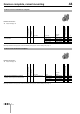
44 Drawings 11 Pushbutton actuator, flush mounting page 29 46 max. 35.95 max. 59.95 27 max. 35.95 45 Front bezel Front bezel with label support Fixing element 2.5 max. 4 max. 35.95 max. 6 1. level min. 65 2. level max. 115 Ø28.2 max. 6 14 20 19 20 1. level Lens level with bezel Lens lower than bezel max. 6 Ø28.2 2. level 26 20 Lens raised above bezel 62 03.2009 Ø23.5 Ø28.
44 Drawings 12 Indicator actuator full face illumination, flush mounting page 27 | Indicator actuator front illumination, flush mounting page 28 13 Indicator full-face illumination complete page 6 | Indicator front illumination complete page 6 63 03.
Drawings 14 Pushbutton complete page 7 15 Illuminated pushbutton complete page 7 16 Selector switch 2 positions complete page 10 17 Selector switch 3 positions complete page 10 64 03.
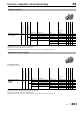
44 Drawings 18 Key lock switch 2 positions complete page 9 19 Indicator actuator full-face illumination page 12 max. 6 max. 6 Ø 28.2 Ø 28.2 max. 6 14 max. 64 Switching element stachable 1. level 19 20 26 20 max. 103 20 Pushbutton actuator page 14 Ø23.5 Ø28.2 level with bezel lower than bezel raised above bezel Switching element 2. level 21 Selector switch actuator 2 positions page 23 | Selector switch actuator 3 positions page 24 65 03.
Drawings 22 Indicator actuator front illumination page 13 23 Pushbutton actuator markable page 16 24 Illuminated pushbutton actuator page 17 66 03.
44 Drawings 25 Pushbutton actuator markable, flush mounting page 31 | Illuminated pushbutton actuator, flush mounting page 32 26 Selector switch actuator 2 positions, flush mounting page 35 | Selector switch actuator 3 positions, flush mounting page 36 67 03.
Drawings 27 Key lock switch 3 positions complete page 9 28 Stop pushbutton, complete page 8 29 Emergency-stop pusbutton, foolproof EN IEC 60947-5-5, complete page 8 30 Keylock switch actuator 2 positions page 21 | Keylock switch actuator 3 positions page 22 68 03.
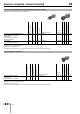
44 Drawings 31 Mushroom-head pushbutton actuator page 21 47 47 max. 6 max. 64 Switching element not stachable max. 53 Ø37 Ø37 32 Emergency-stop pushbutton actuator, foolproof EN IEC 60947-5-5 page 19 Switching element stachable max. 6 ca. 72 33 Stop pushbutton actuator page 20 69 03.
44 Drawings 34 Keylock switch actuator 2 positions, flush mounting page 33 | Keylock switch actuator 3 positions, flush mounting page 34 35 Interlocking pushbutton actuator page 25 36 Double pushbutton actuator page 18 max. 6 29.5 Mounting depth 1. level X [mm] max. 53 - max. 64 44-11144-162 - max. 92 44-13144-162 44-111/ 44-121 max. 100 44-13144-162 44-97044-977 max. 103 44-13144-162 44-13144-162 X 2. level 70 03.2009 2. level 44-111/ 44-121 1.
44 Drawings 37 Potentiometer-drive page 26 38 Interlocking pushbutton actuator, flush mounting page 37 39 Slow-make switching element stackable, front mounting page 42 | Slow-make switching element non-stachable, front mounting page 43 71 03.
Drawings 40 Lamp element, front mounting page 43 41 Slow-make switching element non-stackable, base mounting page 43 42 Lamp transformer page 46 43 Front bezel set without label support, flush mounting page 38 | Front bezel set with label support, flush mounting page 39 72 03.
44 Drawings 44 Emergency-stop enclosure page 19 | Stop pushbutton enclosure page 20 | Pushbutton enclosure page 25 | Emergency-stop enclosures page 48 | Enclosure page 48 Circuit drawing 1 Pushbutton actuator page 14 | Pushbutton actuator markable page 16 | Pushbutton actuator, flush mounting page 29 | Pushbutton actuator markable, flush mounting page 31 2 Pushbutton actuator page 14 | Pushbutton actuator markable page 16 | Mushroom-head pushbutton actuator page 21 | Pushbutton actuator, flush mounting p
Drawings 7 Pushbutton complete page 7 8 Illuminated pushbutton complete page 7 9 Pushbutton complete page 7 10 Illuminated pushbutton complete page 7 11 Selector switch actuator 2 positions page 23 | Selector switch actuator 2 positions, flush mounting page 35 12 Selector switch actuator 3 positions page 24 | Selector switch actuator 3 positions, flush mounting page 36 13 Selector switch actuator 3 positions page 24 | Selector switch actuator 3 positions, flush mounting page 36 14 Selector switch act
44 Drawings 18 Selector switch 3 positions complete page 10 19 Interlocking pushbutton actuator page 25 | Interlocking pushbutton actuator, flush mounting page 37 20 Illuminated pushbutton actuator page 17 | Illuminated pushbutton actuator, flush mounting page 32 21 Pushbutton complete page 7 22 Illuminated pushbutton complete page 7 23 Pushbutton complete page 7 24 Illuminated pushbutton complete page 7 25 Pushbutton complete page 7 26 Illuminated pushbutton complete page 7 75 03.
Drawings 27 Keylock switch actuator 2 positions page 21 | Keylock switch actuator 2 positions, flush mounting page 33 28 Keylock switch actuator 3 positions page 22 | Keylock switch actuator 3 positions, flush mounting page 34 29 Keylock switch actuator 3 positions page 22 | Keylock switch actuator 3 positions, flush mounting page 34 30 Keylock switch actuator 2 positions page 21 | Keylock switch actuator 2 positions, flush mounting page 33 31 Keylock switch actuator 3 positions page 22 | Keylock switch
44 Drawings 38 Slow-make switching element stackable, front mounting page 42 | Slow-make switching element non-stachable, front mounting page 43 | Slow-make switching element non-stackable, base mounting page 43 39 Slow-make switching element stackable, front mounting page 42 | Slow-make switching element non-stachable, front mounting page 43 | Slow-make switching element non-stackable, base mounting page 43 40 Control switch page 11 41 Control switch page 11 42 Control switch page 11 77 03.
Index from Typ-Nr. Typ-Nr. Page 10-1406.1369 .............................44 10-1409.1329 .............................44 10-1412.1279 .............................44 10-1416.1289 .............................44 10-1419.1249 .............................44 10-1420.1219 .............................44 10-1422.1179 .............................44 10-1424.1179 .............................44 10-2506.1082 .............................45 10-2506.1084 .............................45 10-2506.1085 ...............
Index from Typ-Nr. Typ-Nr. Page 44-705.25 ................................... 15 44-705.25 ................................... 30 44-705.26 ................................... 15 44-705.26 ................................... 30 44-705.29 ................................... 15 44-705.29 ................................... 30 44-705.60 ................................... 15 44-705.60 ................................... 30 44-705.62 ................................... 15 44-705.62 ...........................
Index from Typ-Nr. Typ-Nr. Page 44-747.62 ...................................32 44-747.64 ...................................17 44-747.64 ...................................32 44-747.65 ...................................17 44-747.65 ...................................32 44-747.66 ...................................17 44-747.66 ...................................32 44-747.69 ...................................17 44-747.69 ...................................32 44-750.22 ...................................
Phone Fax E-mail Phone Fax E-mail Phone Fax E-mail Phone Fax E-mail Phone Fax E-mail Phone Fax E-mail Phone Fax E-mail Phone Fax E-mail Phone Fax E-mail Phone Fax E-mail Phone Fax E-mail Phone Fax E-mail Phone Fax E-mail EAO reserves the right to alter specifications without further notice E-mail Website EAO AG Tannwaldstrasse 88 4601 Olten, Switzerland info@eao.com www.eao.com Austria +49 201 85 87 0 +49 201 85 87 210 sales.ede@eao.com Belgium +32 3 777 82 36 +32 3 777 84 19 sales.ebl@eao.