
Datasheet


44
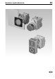
Devices complete, raised mounting
7
03.2009
Continuation see next page
Terminals: ST = Screw terminal
Switching action: MA = Maintained action, M = Momentary action
Contacts: NC = Normally closed, NO = Normally open
Mounting dimensions from page 58, Technical drawing from page 59, Circuit drawing from page 73
Essential Accessories:
d Single-LED page 45
Continuation see next page
Terminals: ST = Screw terminal
Switching action: MA = Maintained action, M = Momentary action
Contacts: NC = Normally closed, NO = Normally open
Mounting dimensions from page 58, Technical drawing from page 59, Circuit drawing from page 73
Pushbutton complete
Front protection
Terminals
Switching action
Contacts Front ring Lens
Ø 28 mm
Typ-Nr.
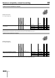
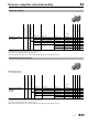
Mounting dimensions
Technical drawing
Circuit drawing
e
Pushbutton complete
non-markable
IP 65 ST MA 1 NC + 1 NO Plastic matt-chrome Plastic black 44-702.20.100 1 14 9 0.037
1 NO Plastic matt-chrome Plastic green 44-702.25.010 1 14 7 0.030
M 1 NC Plastic matt-chrome Plastic red 44-701.22.001 114210.030
1 NC + 1 NO Plastic matt-chrome Plastic black 44-701.20.100 114250.037
1 NO Plastic matt-chrome Plastic green 44-701.25.010 114230.030
Plastic white 44-701.29.010 114230.030
Plastic yellow 44-701.24.010 114230.030
Illuminated pushbutton complete
Front protection
Terminals
Switching action
Contacts Front ring Lens
Ø 28 mm
Typ-Nr.
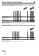
Mounting dimensions
Technical drawing
Circuit drawing
e
Illuminated pushbutton
complete
markable
IP 65 ST MA 1 NC + 1 NO Plastic matt-chrome Plastic white 44-747.29.100 115100.047
1 NO Plastic matt-chrome Plastic green 44-747.25.010 1 15 8 0.040
M 1 NC Plastic matt-chrome Plastic red 44-746.22.001 115220.040
1 NC + 1 NO Plastic matt-chrome Plastic white 44-746.29.100 115260.047
1 NO Plastic matt-chrome Plastic green 44-746.25.010 115240.040
Plastic yellow 44-746.24.010 115240.040