Series Series 61 Comprehensive. Intuitive and versatile. https://eao.
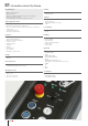
61 Information about the Series Key advantages § § § § § Wide, modular Series Modern design Range of switching elements and ease of mounting Custom marking possible Internationally recognised and approved series Typical application areas Machinery Measurement and control engineering Process engineering (air conditioning systems and heating technology) § Public transportation § Laboratory instruments § § § Functions § § § § § § § § § § Pushbutton Illuminated pushbutton Mushroom-head pushbutton Selector s
Index 61 Flush design Pushbutton round 693 Illuminated pushbutton square 694 Illuminated pushbutton rectangular 695 Illuminated pushbutton round 696 Mushroom-head pushbutton 697 Selector switch 2 positions square 698 Selector switch 2 positions round 699 Selector switch 3 positions square 700 Selector switch 3 positions round 702 Keylock switch 2 positions square 704 Keylock switch 2 positions rectangular 705 Keylock switch 2 positions round 706 Keylock switch 3 positions square 7
61 Index 01 02 03 Raised design Emergency stop switch 758 Components 759 Accessories 777 Technical data 787 Marking 794 Application guidelines 797 04 09 14 17 18 19 22 31 41 45 51 56 57 61 70 71 82 84 92 96 692 eao.
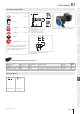
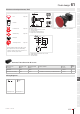
Flush design 61 Pushbutton round, IP65 01 Equipment consisting of (schematic overview) 5.5 max. 02 A Page 759 E 52 03 18x24 Lens C Actuator A 2 Front bezel set Page 763 Anti-twist ring Page 776 E F 54 49 Dimensions [mm] A = Plug-in terminal 2.8 mm x 0.5 mm C = Screw terminal E = Slow-make switching element F = Snap-action switching element Fixing nut NJO NJO 09 Product can differ from the current configuration.
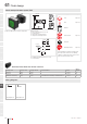
1 Flush design Illuminated pushbutton square, IP65 Equipment consisting of (schematic overview) 5.5 max. 02 A E 03 A Lens Page 759 LED Page 765 C 04 F 2 09 52 18x24 01 Product can differ from the current configuration. 14 E 49 54 Actuator Dimensions [mm] A = Plug-in terminal 2.8 mm x 0.5 mm C = Screw terminal E = Slow-make switching element F = Snap-action switching element 17 18 35 min. C 24 min. A Front bezel set Page 763 Fixing nut +0.2 0 24 min. R1max.
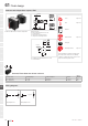
Flush design 61 Illuminated pushbutton rectangular, IP65 Equipment consisting of (schematic overview) 01 5.5 max. 02 A Page 759 E A LED 52 03 18x24 Lens Page 765 C F 2 Actuator Front bezel set Page 763 E 49 04 54 Dimensions [mm] A = Plug-in terminal 2.8 mm x 0.5 mm C = Screw terminal E = Slow-make switching element F = Snap-action switching element NJO Fixing nut NJO 09 Product can differ from the current configuration.
61 Flush design 01 Illuminated pushbutton round, IP65 Equipment consisting of (schematic overview) 5.5 max. 02 A E 18x24 03 C Lens Page 759 LED Page 765 A 04 2 09 52 Product can differ from the current configuration. 14 E F 54 Actuator 49 Dimensions [mm] A = Plug-in terminal 2.8 mm x 0.
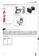
Flush design 61 Mushroom-head pushbutton, IP65 01 Equipment consisting of (schematic overview) 5.5 max. 02 A E Page 759 52 03 18x24 Lens A C Actuator 04 2 F 10 Page 763 Anti-twist ring Page 776 Dimensions [mm] A = Plug-in terminal 2.8 mm x 0.5 mm C = Screw terminal E = Slow-make switching element F = Snap-action switching element A Fixing nut C NJO ± C NJO ± A NJO ± 54 09 Product can differ from the current configuration.
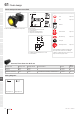
61 Flush design Selector switch 2 positions square, IP65 A E 52 03 A Product can differ from the current configuration. 14 F C 24 min. A Page 763 Fixing nut 24 min. +0.2 0 Switching element Page 767 21.2 22 21.2 + 0.2 0 Each Part Number listed below includes all the black components shown in the 3D-drawing. Mounting cut-outs [mm] A = Solder/Plug-in terminal 2.8 mm x 0.5 mm C = Screw terminal 31 0 I To obtain a complete unit, please select the red components from the pages shown.
Flush design 61 Selector switch 2 positions round, IP65 Equipment consisting of (schematic overview) 01 5.5 max. 02 A E 52 Page 762 A LED 03 18x24 Lever Page 765 C 04 2 7 Actuator Front bezel set Page 763 F 49 54 Dimensions [mm] A = Plug-in terminal 2.8 mm x 0.5 mm C = Screw terminal E = Slow-make switching element F = Snap-action switching element NJO Anti-twist ring E Page 776 NJO 14 17 C A 18 NJO Fixing nut 09 Product can differ from the current configuration.
61 Flush design Selector switch 3 positions square, IP65 01 A A Page 762 LED Page 765 C 04 2 F 7 Product can differ from the current configuration. 14 E 54 49 Actuator Dimensions [mm] A = Plug-in terminal 2.8 mm x 0.5 mm C = Screw terminal E = Slow-make switching element F = Snap-action switching element 17 18 35 min. C 24 min. A Front bezel set Page 763 Fixing nut +0.2 0 24 min. R1max. Switching element Page 771 21.2 19 22 21.2 + 0.
Flush design 61 Wiring diagrams 01 x2+ 02 03 x1- 04 Wiring diagram 301 09 14 17 18 19 22 31 41 45 51 56 57 61 Comprehensive, intuitive and versatile. The tried-and-tested EAO Series 61. 70 71 A versatile and modern range for complex industrial applications. . Wide, modular series . Modern design . Ease of mounting . Custom marking possible . Internationally recognised and approved series 82 84 92 www.eao.com 01/2019 § eao.
61 Flush design Selector switch 3 positions round, IP65 01 A A Lever Page 762 LED Page 765 18x24 E 52 03 C 04 2 7 09 Equipment consisting of (schematic overview) 5.5 max. 02 Product can differ from the current configuration. 14 F 49 E 54 Dimensions [mm] A = Plug-in terminal 2.8 mm x 0.
Flush design 61 Wiring diagrams 01 x2+ 02 03 x1- 04 Wiring diagram 301 09 14 17 18 19 22 31 41 45 51 56 57 61 70 71 82 84 92 96 01/2019 § eao.
61 Flush design Keylock switch 2 positions square, IP65 A E 52 03 A Key C 04 2 F 27 09 Equipment consisting of (schematic overview) 5.5 max. 02 18x24 01 Product can differ from the current configuration. 14 E 49 54 Dimensions [mm] A = Plug-in terminal 2.8 mm x 0.5 mm C = Screw terminal E = Slow-make switching element F = Snap-action switching element 17 18 35 min. C 24 min. A Keylock front bezel Page 764 Actuator Front bezel set Page 763 +0.2 0 24 min. R1max. 21.2 19 22 21.
Flush design 61 Keylock switch 2 positions rectangular, IP65 Equipment consisting of (schematic overview) 01 5.5 max. 02 A E 52 03 18x24 A Key C 04 2 Keylock front bezel Page 764 F 27 E 49 54 Dimensions [mm] A = Plug-in terminal 2.8 mm x 0.5 mm C = Screw terminal E = Slow-make switching element F = Snap-action switching element Actuator NJO Front bezel set Page 763 NJO 09 Product can differ from the current configuration.
61 Flush design Keylock switch 2 positions round, IP65 A E 52 03 A Key C 04 2 27 09 Equipment consisting of (schematic overview) 5.5 max. 02 18x24 01 Product can differ from the current configuration. 14 F E 49 54 Dimensions [mm] A = Plug-in terminal 2.8 mm x 0.
Flush design 61 Wiring diagrams 01 02 03 04 Wiring diagram 78 Wiring diagram 79 09 14 17 18 19 22 31 41 45 51 EAO Downloads. www.eao.com/downloads 56 EAO creates possibilities. Since 1947. 57 61 70 71 On our website you can download technical data, assembly instructions, catalogs, brochures and much more. 82 84 92 www.eao.com 01/2019 § eao.
61 Flush design Keylock switch 3 positions square, IP65 01 A 18x24 E 52 03 A Key C 04 2 F 27 09 Equipment consisting of (schematic overview) 5.5 max. 02 Product can differ from the current configuration. 14 54 Keylock front bezel Dimensions [mm] A = Plug-in terminal 2.8 mm x 0.5 mm C = Screw terminal E = Slow-make switching element F = Snap-action switching element 17 18 E 49 35 min. C 24 min. A Page 764 Actuator Front bezel set Page 763 +0.2 0 24 min. R1max.
Flush design 61 Wiring diagrams 01 02 03 04 Wiring diagram 80 Wiring diagram 81 Wiring diagram 82 Wiring diagram 83 09 14 17 18 19 22 31 41 45 51 56 57 61 70 71 82 84 92 96 01/2019 § eao.
61 Flush design Keylock switch 3 positions rectangular, IP65 01 A 18x24 E 52 03 A Key C 04 2 F 27 09 Equipment consisting of (schematic overview) 5.5 max. 02 Product can differ from the current configuration. 14 E 49 Dimensions [mm] A = Plug-in terminal 2.8 mm x 0.
Flush design 61 Wiring diagrams 01 02 03 04 Wiring diagram 80 Wiring diagram 81 Wiring diagram 82 Wiring diagram 83 09 14 17 18 19 22 31 41 45 51 56 57 61 70 71 82 84 92 96 01/2019 § eao.
61 Flush design Keylock switch 3 positions round, IP65 01 A A 18x24 E 52 03 Key C 04 2 27 09 Equipment consisting of (schematic overview) 5.5 max. 02 Product can differ from the current configuration. 14 F E 49 Dimensions [mm] A = Plug-in terminal 2.8 mm x 0.
Flush design 61 Wiring diagrams 01 02 03 04 Wiring diagram 80 Wiring diagram 81 Wiring diagram 82 Wiring diagram 83 09 14 17 18 19 22 31 41 45 51 Follow us. We are on LinkedIn! 56 EAO creates possibilities. Since 1947. 57 61 70 71 Come take a look at our LinkedIn profi le today! Be sure to give us a follow so that you can fully interact with us. 82 https://www.linkedin.com/company/eao/ 84 92 www.eao.com 01/2019 § eao.
61 Flush design 01 Indicator with lamp element square, IP65 Equipment consisting of (schematic overview) 5.5 max. 02 Lens Page 759 LED Page 765 03 04 2 09 49 Actuator Product can differ from the current configuration. Dimensions [mm] 14 17 35 min. C 24 min. A B Front bezel set Page 763 Fixing nut 21.2 + 0.2 0 18 24 min. R1 max. 19 21.2 Mounting cut-outs [mm] A = Solder/Plug-in terminal 2.8 mm x 0.5 mm B = Solder terminal C = Screw terminal 22 31 41 45 51 + 0.
Flush design 61 Indicator with lamp element rectangular, IP65 Equipment consisting of (schematic overview) Lens 01 5.5 max. 02 Page 759 03 LED Page 765 04 2 49 09 Actuator Dimensions [mm] Front bezel set Page 763 Product can differ from the current configuration. NJO C NJO A 14 B 17 Each Part Number listed below includes all the black components shown in the 3D-drawing. To obtain a complete unit, please select the red components from the pages shown.
61 Flush design 01 Indicator with lamp element round, IP65 Equipment consisting of (schematic overview) 5.5 max. 02 03 Lens Page 759 LED Page 765 04 2 09 49 Actuator Product can differ from the current configuration. Dimensions [mm] 14 NJO 17 A B NJO NJO C 18 Front bezel set Page 763 Anti-twist ring Page 776 Fixing nut 19 ± Mounting cut-outs [mm] A = Solder/Plug-in terminal 2.8 mm x 0.
Flush design 61 Indicator without lamp element square, IP65 Equipment consisting of (schematic overview) Ø14.5 5.5 max. D Page 759 A LED 02 B 73 03 18x24 Lens 01 Page 765 C 2 04 54 49 Actuator Front bezel set Page 763 Dimensions [mm] A = Plug-in terminal 2.8 mm x 0.5 mm B = Solder terminal C = Screw terminal D = Flasher Fixing nut 35 min. C 24 min. A 09 Product can differ from the current configuration. 14 17 B 18 +0.2 0 Page 775 19 21.2 Lamp element 24 min. R1 max.
61 Flush design Indicator without lamp element rectangular, IP65 Equipment consisting of (schematic overview) 5.5 max. 02 Ø14.5 01 B D 18x24 03 A Lens Page 759 LED Page 765 C 04 2 09 73 54 49 Actuator Product can differ from the current configuration. 14 Dimensions [mm] A = Plug-in terminal 2.8 mm x 0.
Flush design 61 Indicator without lamp element round, IP65 Equipment consisting of (schematic overview) Page 759 LED Page 765 Ø14.5 5.5 max. 02 B D 73 03 18x24 Lens 01 A A 2 Actuator Front bezel set Page 763 Anti-twist ring Page 776 54 04 49 Dimensions [mm] A = Plug-in terminal 2.8 mm x 0.5 mm B = Solder terminal C = Screw terminal D = Flasher NJO NJO 09 Product can differ from the current configuration.
61 Flush design Buzzer Equipment consisting of (schematic overview) 5.5 max. 02 03 15 01 A Actuator 04 45 2 14 17 Thrust piece Product can differ from the current configuration. Dimensions [mm] A = Plug-in terminal 2.8 mm x 0.5 mm Fixing nut General information NJO • Change polarity for continuous or intermittent tone Each Part Number listed below includes all the black components shown in the 3D-drawing.
Flush design 61 Potentiometer square, IP65 01 Equipment consisting of (schematic overview) 12 23 max. 02 03 Ø 16 Actuator 04 4 max. 300 Front bezel Dimensions [mm] Fixing nut 09 Product can differ from the current configuration. 14 General information NJO • Resistance 10 kOhms / linear 17 PLQ 3 NBY Each Part Number listed below includes all the black components shown in the 3D-drawing.
61 Flush design 01 Component layouts 02 A 03 C 04 09 14 a b c B Component layout 30 A = Terminals (rear side) B = Conductor colour of flat ribbon cable C = a = blue, b = red, c = yellow 17 18 19 22 31 41 45 51 56 57 61 Compact, robust, reliable. The Series 61 E-Stop compact. 70 71 UL-certified – safety in a compact design for handheld control units. . Very low back panel depth (21.2 mm) . High front protection IP69K and IP67 . Robust mono-block design . Mechanically decoupled triggering .
Flush design 61 Potentiometer round, IP65 01 Equipment consisting of (schematic overview) 12 23 max. 02 03 Ø 16 Actuator 04 4 max. 300 Front bezel Dimensions [mm] 09 Product can differ from the current configuration. Anti-twist ring 14 General information NJO Fixing nut • Resistance 10 kOhms / linear NJO 17 Each Part Number listed below includes all the black components shown in the 3D-drawing.
61 Flush design 01 Component layouts 02 A 03 C 04 09 14 a b c B Component layout 30 A = Terminals (rear side) B = Conductor colour of flat ribbon cable C = a = blue, b = red, c = yellow 17 18 19 22 31 41 45 51 56 57 61 70 71 82 84 92 96 724 eao.
Raised design 61 Illuminated pushbutton square, IP65 01 Equipment consisting of (schematic overview) 8 max. Page 759 E A LED 44 03 18x24 Lens 02 A Page 765 C F 42 10.6 04 E 46 Actuator Dimensions [mm] A = Plug-in terminal 2.8 mm x 0.5 mm C = Screw terminal E = Slow-make switching element F = Snap-action switching element 35 min. Page 767 24 min. 17 C A 24 x 24 15 To obtain a complete unit, please select the red components from the pages shown. Ø 16.2 19 18 x 18 18 x 24 Ø18 + 0.
61 Raised design 01 Illuminated pushbutton square, IP65 Equipment consisting of (schematic overview) 02 8 max. A E A Lens Page 759 LED Page 765 C 04 F 42 10.6 E 46 Actuator Product can differ from the current configuration. 14 Dimensions [mm] A = Plug-in terminal 2.8 mm x 0.5 mm C = Screw terminal E = Slow-make switching element F = Snap-action switching element 17 35 min. 24 min. 18 Fixing nut C Switching element A Ø 16.
Raised design 61 Illuminated pushbutton rectangular, IP65 01 Equipment consisting of (schematic overview) 8 max. Page 759 E A LED 44 03 18x24 Lens 02 A Page 765 C F 42 10.6 04 E 46 Actuator Dimensions [mm] A = Plug-in terminal 2.8 mm x 0.5 mm C = Screw terminal E = Slow-make switching element F = Snap-action switching element Page 767 35 min. 24 min. 17 C A 24 x 24 15 To obtain a complete unit, please select the red components from the pages shown. Ø 16.
61 Raised design 01 Illuminated pushbutton round, IP65 Equipment consisting of (schematic overview) 02 8 max. A E A Lens Page 759 LED Page 765 C 04 09 18x24 03 44 F 42 10.6 E 46 Actuator Product can differ from the current configuration. 14 Dimensions [mm] A = Plug-in terminal 2.8 mm x 0.
Raised design 61 Illuminated pushbutton without front bezel round, IP65 01 Equipment consisting of (schematic overview) 8 max. Page 759 Front bezel Page 764 02 E 44 03 18x24 Lens A A C LED Page 765 F 10.6 42 Dimensions [mm] A = Plug-in terminal 2.8 mm x 0.5 mm C = Screw terminal E = Slow-make switching element F = Snap-action switching element Actuator Fixing nut NJO NJO 09 Product can differ from the current configuration.
61 Raised design 01 Mushroom-head pushbutton, IP65 Equipment consisting of (schematic overview) 02 8 max. A E C A 04 Product can differ from the current configuration. 14 46 F NJO NJO 18 19 Page 764 Fixing nut C Switching element A Page 767 Each Part Number listed below includes all the black components shown in the 3D-drawing. To obtain a complete unit, please select the red components from the pages shown.
Raised design 61 Selector switch 2 positions square, IP65 Equipment consisting of (schematic overview) 8 max. E Page 762 C Front bezel 02 A 44 03 18x24 Lever 01 Page 763 A 04 7 LED E 14 Page 765 F 46 42 Dimensions [mm] A = Plug-in terminal 2.8 mm x 0.
61 Raised design 01 Selector switch 2 positions round, IP65 Equipment consisting of (schematic overview) 8 max. 02 A 03 A C 04 F 42 Product can differ from the current configuration. LED Page 765 46 Dimensions [mm] A = Plug-in terminal 2.8 mm x 0.
Raised design 61 Selector switch 3 positions square, IP65 Equipment consisting of (schematic overview) 8 max. E Page 762 C Front bezel 02 A 44 03 18x24 Lever 01 Page 763 A 04 7 LED E 14 Page 765 F 46 42 Dimensions [mm] A = Plug-in terminal 2.8 mm x 0.
61 Raised design 01 Wiring diagrams x2+ 02 03 x1- 04 Wiring diagram 301 09 14 17 18 19 22 31 41 45 51 EAO Downloads. www.eao.com/downloads 56 EAO creates possibilities. Since 1947. 57 61 70 71 On our website you can download technical data, assembly instructions, catalogs, brochures and much more. 82 84 92 www.eao.com 96 734 eao.
Raised design 61 Selector switch 3 positions round, IP65 Equipment consisting of (schematic overview) 8 max. E Page 762 A LED 02 A 44 03 18x24 Lever 01 Page 765 C 04 7 F 42 14 E 46 Actuator Anti-twist ring Page 776 Dimensions [mm] A = Plug-in terminal 2.8 mm x 0.
61 Raised design 01 Wiring diagrams x2+ 02 03 x1- 04 Wiring diagram 301 09 14 17 18 19 22 31 41 45 51 56 57 61 70 71 82 84 92 96 736 eao.
Raised design 61 Keylock switch 2 positions square, IP65 01 Equipment consisting of (schematic overview) F 42 03 18x24 Key 02 A 6.5 max. A C 04 10 Keylock front bezel E 35 Page 764 E 44 46 Dimensions [mm] A = Plug-in terminal 2.8 mm x 0.5 mm C = Screw terminal E = Slow-make switching element F = Snap-action switching element Actuator Anti-twist ring NJO Page 776 NJO 09 Product can differ from the current configuration.
61 Raised design 01 Keylock switch 2 positions rectangular, IP65 Equipment consisting of (schematic overview) 02 A 6.5 max. F A Key C 04 10 E 35 Product can differ from the current configuration. 14 E 44 46 Dimensions [mm] A = Plug-in terminal 2.8 mm x 0.
Raised design 61 Keylock switch 2 positions round, IP65 01 Equipment consisting of (schematic overview) F 42 03 18x24 Key 02 A 6.5 max. A C 04 10 Keylock front bezel E 35 Page 764 E 44 46 Dimensions [mm] A = Plug-in terminal 2.8 mm x 0.5 mm C = Screw terminal E = Slow-make switching element F = Snap-action switching element Actuator Anti-twist ring NJO Page 776 NJO 09 Product can differ from the current configuration.
61 Raised design Keylock switch 3 positions square, IP65 01 Equipment consisting of (schematic overview) 02 A 6.5 max. F A Key C 04 10 E 35 Product can differ from the current configuration. 14 17 18 46 Keylock front bezel Dimensions [mm] A = Plug-in terminal 2.8 mm x 0.
Raised design 61 Wiring diagrams 01 02 03 04 Wiring diagram 80 Wiring diagram 81 Wiring diagram 82 Wiring diagram 83 09 14 17 18 19 22 31 41 45 51 56 57 61 70 71 82 84 92 96 01/2019 § eao.
61 Raised design Keylock switch 3 positions rectangular, IP65 01 Equipment consisting of (schematic overview) 02 A 6.5 max. F A Key C 04 10 E 35 Product can differ from the current configuration. 14 17 46 Keylock front bezel Dimensions [mm] A = Plug-in terminal 2.8 mm x 0.
Raised design 61 Wiring diagrams 01 02 03 04 Wiring diagram 80 Wiring diagram 81 Wiring diagram 82 Wiring diagram 83 09 14 17 18 19 22 31 41 45 51 Follow us. We are on YouTube! 56 EAO ermöglicht. Seit 1947. 57 61 70 71 Come take a look at our YouTube profi le today! Be sure to give us a follow so that you can fully interact with us. 82 https://www.youtube.com/user/eaoswitches 84 92 www.eao.com 01/2019 § eao.
61 Raised design Keylock switch 3 positions round, IP65 01 Equipment consisting of (schematic overview) 02 A 6.5 max. F A Key C 04 10 E 35 Product can differ from the current configuration. 14 17 46 Keylock front bezel Dimensions [mm] A = Plug-in terminal 2.8 mm x 0.
Raised design 61 Wiring diagrams 01 02 03 04 Wiring diagram 80 Wiring diagram 81 Wiring diagram 82 Wiring diagram 83 09 14 17 18 19 22 31 41 45 51 56 57 61 70 71 82 84 92 96 01/2019 § eao.
61 Raised design 01 Indicator with lamp element square, IP65 Equipment consisting of (schematic overview) 02 8 max. Lens Page 759 LED Page 765 03 04 Actuator Dimensions [mm] 17 A 18 19 Ø16.2 +0.2 0 24 x 24 18 x 18 18 x 24 Ø18 15 +0.1 0 Each Part Number listed below includes all the black components shown in the 3D-drawing. Ø16.2 To obtain a complete unit, please select the red components from the pages shown. + 0.2 0 Mounting cut-outs [mm] A = Solder/Plug-in terminal 2.8 mm x 0.
Raised design 61 Indicator with lamp element rectangular, IP65 01 Equipment consisting of (schematic overview) 02 8 max. Lens Page 759 03 LED Page 765 10.6 04 42 09 Actuator Dimensions [mm] A 18 min. Each Part Number listed below includes all the black components shown in the 3D-drawing. B To obtain a complete unit, please select the red components from the pages shown. Ø16.2 +0.2 0 17 24 x 24 18 x 18 18 x 24 Ø18 15 + 0.1 0 0 24 min. 14 C 1.7 -0.1 35 min. 24 min.
61 Raised design 01 Indicator with lamp element round, Ø 18 mm, IP65 Equipment consisting of (schematic overview) 02 8 max. 03 04 09 10.6 Lens Page 759 LED Page 765 42 Actuator Product can differ from the current configuration. Dimensions [mm] 14 NJO Fixing nut 17 18 NJO Each Part Number listed below includes all the black components shown in the 3D-drawing. To obtain a complete unit, please select the red components from the pages shown.
Raised design 61 Indicator without front bezel round, Ø 24 mm, IP65 01 Equipment consisting of (schematic overview) 02 8 max. Lens Page 759 Front bezel Page 764 LED Page 765 03 04 10.6 42 Dimensions [mm] 09 Product can differ from the current configuration. 14 Actuator NJO NJO C A B 17 NJO Fixing nut 18 Each Part Number listed below includes all the black components shown in the 3D-drawing.
61 Raised design 01 Indicator without lamp element square, IP65 Equipment consisting of (schematic overview) 02 8 max. Lens Page 759 LED Page 765 03 04 09 10.6 42 Actuator Product can differ from the current configuration.
Raised design 61 Indicator without lamp element rectangular, IP65 01 Equipment consisting of (schematic overview) 02 8 max. Lens Page 759 03 LED Page 765 10.6 04 42 Actuator Dimensions [mm] Fixing nut Lamp element Page 775 NJO Y NJO Y NJO 14 17 ± ± NJO Each Part Number listed below includes all the black components shown in the 3D-drawing.
61 Raised design 01 Indicator without lamp element round, IP65 Equipment consisting of (schematic overview) 02 8 max. 03 04 09 10.6 Product can differ from the current configuration.
Raised design 61 Indicator without front bezel round, IP65 Equipment consisting of (schematic overview) Front bezel Ø14.5 8 max. D A Page 764 02 B Page 759 65 03 18x24 Lens 01 C Page 765 10.6 Dimensions [mm] A = Plug-in terminal 2.8 mm x 0.5 mm B = Solder terminal C = Screw terminal D = Flasher Actuator Fixing nut NJO NJO 14 17 A B Page 775 18 Each Part Number listed below includes all the black components shown in the 3D-drawing.
61 Raised design Stop switch, IP65 Equipment consisting of (schematic overview) 02 A 03 35.6 18x24 01 6 max. 59.5 41 Actuator 04 C 46 09 Product can differ from the current configuration. 14 Dimensions [mm] A = Plug-in terminal 2.8 mm x 0.
Raised design 61 Emergency stop switch compact, foolprof, EN IEC 60947-5-5, IP66, IP67, IP69K 01 Ø 27 Equipment consisting of (schematic overview) 02 A Actuator 03 6 max. 27.5 21.2 04 Ø 40 Seal Anti-twist ring A 09 Product can differ from the current configuration. 14 6 max. Fixing nut 27.5 Each Part Number listed below includes all the black components shown in the 3D-drawing. 21.2 17 Dimensions [mm] A = Plug-in terminal 2.8 mm x 0.
61 Raised design 01 Contacts Switching action Terminal Lens colour Lens material Type of illumination Dimensions Part No. Wiring diagram 1 NC / 2 NO Maintained Plug-in terminal Red Plastic non illuminated Ø 40 mm 61-6461.
Raised design 61 Component layouts 01 02 03 23 11 12 24 11 23 24 24 11 12 04 33 34 23 12 31 32 09 Component layout 73 Component layout 74 Component layout 75 14 17 21 18 23 24 11 12 22 11 12 -X X1 2+ -X X1 2+ 11 12 19 -X X1 2+ 22 Component layout 76 Component layout 77 Component layout 78 31 41 45 51 56 57 61 Compact, robust, reliable. The Series 61 E-Stop compact. 70 71 UL-certified – safety in a compact design for a wide variety of applications. .
61 Raised design Emergency stop switch, IP65 Equipment consisting of (schematic overview) 02 A 03 18x24 01 6 max. 35.6 Actuator 41 04 C 46 09 Fixing nut Product can differ from the current configuration. 14 Dimensions [mm] A = Plug-in terminal 2.8 mm x 0.5 mm C = Screw terminal Switching element Page 767 General information • Application as per DIN EN ISO 13850 and EN 60204-1 17 Each Part Number listed below includes all the black components shown in the 3D-drawing.
Components 61 01 Lens square, raised design 02 Lens material Lens colour Lens optics Lens shape Lens illumination Dimensions Part No. Plastic Smokey black transparent flush illuminative 20 mm x 20 mm 61-9351.1 Red transparent flush illuminative 20 mm x 20 mm 61-9351.2 Orange transparent flush illuminative 20 mm x 20 mm 61-9351.3 Yellow transparent flush illuminative 20 mm x 20 mm 61-9351.4 Green transparent flush illuminative 20 mm x 20 mm 61-9351.
61 Components 01 02 Lens round, raised design Lens material Lens colour Lens optics Lens shape Lens illumination Dimensions Part No. Plastic Smokey black transparent flush illuminative Ø 19,7 mm 61-9642.1 Red transparent flush illuminative Ø 19,7 mm 61-9642.2 Orange transparent flush illuminative Ø 19,7 mm 61-9642.3 Yellow transparent flush illuminative Ø 19,7 mm 61-9642.4 Green transparent flush illuminative Ø 19,7 mm 61-9642.
Components 61 01 Lens plastic with symbol Lens material Lens colour Lens optics Lens shape Lens illumination Symbol Dimensions Part No. Plastic Red transparent flush illuminative Ring Ø 19,7 mm 61-9643.201 Orange transparent flush illuminative Ring Ø 19,7 mm 61-9643.301 Yellow transparent flush illuminative Ring Ø 19,7 mm 61-9643.401 Green transparent flush illuminative Ring Ø 19,7 mm 61-9643.501 Blue transparent flush illuminative Ring Ø 19,7 mm 61-9643.
61 Components 01 Mushroom-head cap 02 03 Lens material Lens colour Lens optics Lens shape Lens illumination Part No. Plastic Black opaque flush non illuminative 61-9593.0 Red opaque flush non illuminative 61-9593.2 04 09 Lever raised design 14 17 Lever material Lever colour Lever illumination Lever bar colour Lever shape Part No. plastic Black illuminative Red short 52-928.20 Black illuminative Orange short 52-928.30 Black illuminative Yellow short 52-928.
Components 61 01 02 Marking plate Marking plate material Marking plate colour Marking plate optics Marking plate illumination Part No. Plastic Colourless transparent illuminative 61-9707.7 03 Additional information 04 • Can be hot stamped 09 14 Front bezel set flush design Mounting cut-out Dimensions Part No. Black 21 mm x 21 mm 24 mm x 24 mm 61-9930.0 Plastic Silver 21 mm x 21 mm 24 mm x 24 mm 61-9930.4 Plastic Black 21 mm x 27 mm 24 mm x 30 mm 61-9931.
61 Components 01 02 03 04 Front bezel set mushroom head pushbutton Front bezel material Front bezel colour Front bezel type Dimensions Part No. Aluminium Nature flush Ø 40 mm 61-9934.8 Additional information • The colour of anodised aluminium parts can vary due to technical production reasons 09 14 17 Keylock front bezel Material Colour Dimensions Part No. plastic Black 18 mm x 18 mm 61-9220.0 Black 24 mm x 18 mm 61-9230.0 Black Ø 18 mm 61-9210.0 Black 24 mm x 24 mm 61-9250.
Components 61 01 Single-LED, T1 3/4 MG Illumination colour Operating voltage Operation current Lumi. Intensity Dom. Wavelength Part No. Wiring diagram Red 6 V DC +10% 15 mA ±15 % 350 mcd 630 nm 10-2J06.3142 55 12 V AC/DC +10% 7 - 14 mA ±15 % 330 mcd 630 nm 10-2J09.1062 55 24 V AC/DC +10% 7 - 14 mA ±15 % 330 mcd 630 nm 10-2J12.1062 55 28 V AC/DC +10% 7 - 14 mA ±15 % 330 mcd 630 nm 10-2J13.1062 55 48 V AC/DC +10% 4 - 8 mA ±15 % 200 mcd 630 nm 10-2J19.
61 Components 01 Wiring diagrams x2+ 02 03 x1- 04 Wiring diagram 55 09 14 Bi-colour LED, BA9s 17 18 19 Illumination colour Operating voltage Operation current Lumi. Intensity Dom. Wavelength Part No. Wiring diagram Red / Green 24 V DC +10% 15/14 mA ±15 % 600/630 mcd 625 / 525 nm 10-A312.
Components 61 01 Filament lamp Operating voltage Operation current Part No. Wiring diagram 12 V AC/DC 75 mA ±10 % 10-1309.1309 4 14 V AC/DC 80 mA ±10 % 10-1310.1319 4 24 V AC/DC 35 mA ±10 % 10-1312.1229 4 28 V AC/DC 40 mA ±10 % 10-1313.1249 4 36 V AC/DC 30 mA ±10 % 10-1316.1209 4 48 V AC/DC 25 mA ±10 % 10-1319.
61 Components 01 Wiring diagrams 02 11 X2+ 11 21 X2+ 11 21 31 X2+ 13 X2+ 12 12 22 12 22 32 14 13 X2+ 2 3 13 21 X2+ 13 21 31 X2+ X1– 1 4 14 22 14 22 32 03 X1– X1– X1– X1– 14 X1– X1– 04 Wiring diagram 306 09 Wiring diagram 307 Wiring diagram 308 13 21 33 X2+ 13 23 X2+ 13 23 33 X2+ 14 22 34 X1– 14 24 X1– 14 24 34 Wiring diagram 310 Wiring diagram 311 Wiring diagram 313 Wiring diagram 314 14 17 18 19 Wiring diagram 315 Wiring diagram 317 X1–
Components 61 01 Slow-make switching switching element 2 positions with plug-in terminal 02 Switching voltage Switching current Contacts Contact material Part No. Wiring diagram Component Layout 250 V 5A 1 NO Silver 61-8610.17 310 49 5A 2 NO Silver 61-8620.17 317 52 5A 1 NC Silver 61-8640.17 306 46 5A 2 NC Silver 61-8650.17 307 51 5A 1 NC / 1 NO Silver 61-8670.17 313 48 0.3 A 1 NO Gold-plated silver 61-8610.37 310 49 0.3 A 2 NO Gold-plated silver 61-8620.
61 Components 01 Slow-make switching switching element 2 positions with screw terminal 02 03 Switching voltage Switching current Contacts Contact material Part No. 250 V 5A 1 NO Silver 61-8610.11 310 50 5A 1 NC Silver 61-8640.11 306 47 5A 1 NO Silver 61-8615.11 309 55 5A 2 NO Silver 61-8625.11 316 57 5A 1 NC Silver 61-8645.11 305 53 5A 2 NC Silver 61-8655.11 319 56 5A 1 NC / 1 NO Silver 61-8675.
Components 61 01 Snap-action switching element 3 positions with plug-in terminal 02 Contacts Contact material Part No. Wiring diagram Component Layout 2 NO Silver 61-8520.12 317 60 Gold 61-8520.22 317 60 Silver 61-8550.12 307 59 Gold 61-8550.22 307 59 Gold 61-8574.22 313 58 Silver 61-8574.
61 Components 01 Slow-make switching switching element 3 positions with plug-in terminal 02 03 04 09 Component Layout Contacts Contact material Part No. Wiring diagram 2 NO Silver 61-8720.17 317 63 2 NC Silver 61-8750.17 307 63 1 NC / 1 NO Silver 61-8770.17 313 61 2 NO Gold 61-8720.37 317 63 2 NC Gold 61-8750.37 307 62 1 NC / 1 NO Gold 61-8770.
Components 61 Wiring diagrams 01 13 23 21 11 13 21 14 24 22 12 14 22 02 03 04 Wiring diagram 316 Wiring diagram 319 Wiring diagram 320 09 Component layouts 13 14 11 14 13 12 14 17 18 21 21 22 23 22 24 19 Component layout 54 Component layout 56 Component layout 57 22 31 41 Switching element E-stop Component Layout Switching voltage Switching current Contacts Contact material Terminal Part No. Wiring diagram 250 V 5A 1 NC Silver Screw terminal 61-8745.
61 Components 01 Component layouts 11 02 12 13 14 11 12 11 13 21 21 22 21 22 12 14 22 03 04 09 Component layout 53 14 11 21 12 22 Component layout 54 Component layout 56 Component layout 64 Component layout 65 17 18 19 Component layout 66 22 31 41 Switching element Stop switch Switching system Contacts Contact material Terminal Part No. Slow-make switching element 1 NC Gold Plug-in terminal 61-8745.37 321 64 2 NC Gold Plug-in terminal 61-8755.
Components 61 Component layouts 01 11 13 21 11 21 02 03 12 14 12 22 22 04 Component layout 64 Component layout 65 Component layout 66 09 14 Flasher element Product attributes Terminal Part No. Wiring diagram Only for Indicator actuator (without indicator complete) Soldering terminal 61-8000.
61 Components 01 Wiring diagrams x2+ 02 03 x1- 04 Wiring diagram 4 09 14 Component layouts 17 X2 X1 18 X1 X2 19 22 Component layout 31 Component layout 32 31 41 45 Anti-twist ring Material Mounting cut-out Part No. metal Ø 16.2 mm 51-910 Ø 22.3 mm 61-9912.0 51 56 57 61 70 71 82 84 92 96 776 eao.
Accessories 61 Front side 01 02 03 04 Legend frame Dimensions Material Colour Surface Mounting type Part No. 30 mm x 50 mm aluminium Black anodised adhesive 61-9980.0 09 14 Additional information • For devices with front dimension Ø 25 mm, flush design • The colour of anodised aluminium parts can vary due to technical production reasons 4 18 14.5 19 Ø25 17 22 35 ± 0.3 50 ± 0.3 23.5 0 30 -0.
61 Accessories 01 02 03 04 09 Blind plug raised design Dimensions Material Colour 24 mm x 24 mm plastic Black Mounting cut-out Part No. 18 mm x 18 mm plastic Black Ø 16.2 mm 51-948.0 18 mm x 24 mm plastic Black Ø 16.2 mm 51-947.0 Ø 18 mm plastic Black Ø 16.2 mm 51-949.0 61-9450.0 Additional information • Blind plugs fit also in mounting cut-outs with anti-twist device 14 17 18 19 22 Blind plug flush design Dimensions Material Colour Mounting cut-out Part No.
Accessories 61 01 02 Protective cap Product attributes Material Colour Optics Part No. For front bezel set 24 mm x 30 mm, flush design silicone Colourless transparent 61-9927.2 For front bezel Ø 25 mm silicone Colourless transparent 84-9103.7 03 04 Additional information • For flat lens profil only 09 • When using the front protection cover the external sealing in the actuator has to be removed 14 Master key 17 Product attributes Material Part No.
61 Accessories 01 02 Protective cover flush design Product attributes Dimensions Material Colour Optics Mounting cut-out Part No. Hinged, with means for sealing, for device with front dimension 24 mm x 24 mm 24 mm x 24 mm plastic Colourless transparent 21 mm x 21 mm 61-9921.0 Hinged, with means for sealing, for device with front dimension 24 mm x 30 mm 30 mm x 24 mm plastic Colourless transparent 27 mm x 21 mm 61-9922.
Accessories 61 Rear side 01 02 03 Diode element Component Layout Terminal Diode Part No. Wiring diagram Plug-in terminal 1 61-8101.02 302 33 2 61-8102.02 303 34 04 09 Wiring diagrams 14 X2+ 2 X2+ 2 3 X1– 1 X1– 1 4 17 18 19 Wiring diagram 302 Wiring diagram 303 22 Component layouts X2 X2 X1 31 X1 12+ 41 3+ 412+ 45 51 Component layout 33 Component layout 34 56 57 Flat receptacle Product attributes Material Part No. 2.8 x 0.
61 Accessories 01 02 Terminal cover Product attributes Material Part No. For snap-action switching element with soldering terminal plastic 61-9830.2 Product attributes Dimensions Part No. 5 spaces 62.5 mm x 15 mm x 60 mm 02-912.1 10 spaces 125 mm x 15 mm x 60 mm 02-912.2 15 spaces 187.6 mm x 15 mm x 60 mm 02-912.3 20 spaces 250 mm x 15 mm x 60 mm 02-912.4 Product attributes Material Part No. For snap-action switching element, max.
Accessories 61 Component layouts 01 02 A B D C 03 23.60 7.62 7.62 04 Ø1.0 (8x) 17.70 4.5 4.5 4.5 11, 13, 21, 23, 3+ 12, 14, 22, 24, 4- X2 21, 23, 31, 33, 122, 24, 32, 34, 2+ E X1 09 11, 13, 31 12, 14, 32 14 Component layout 67 17 Dimensions [mm] A = PCB plug-in base B = Terminals (rear side) C = Drilling plan (component side) D = Occupancy plan (component side) E = Anti-rotation device 18 19 A B 22 D C 31 23.00 6.80 6.80 41 Ø 1.
61 Accessories 01 Component layouts 02 A B D C 03 13.10 04 Ø1.0 (2x) E 14 17 18 X2 X2 X1 X1 X2 4.5 09 X1 Component layout 69 Dimensions in [mm] A = PCB plug-in base B = Terminals (rear side) C = Drilling plan (component side) D = Occupancy plan (component side) E = Anti-rotation device F = Positioning hole 19 Series resistor 22 31 41 Operating voltage Resistance Part No. 110 V AC 2.7 kOhm 02-904.0 125 V AC 3.3 kOhm 02-904.1 145 V AC 4.7 kOhm 02-904.
Accessories 61 Mounting 01 02 03 Enclosure Dimensions Material IP Protection Part No. 65 mm x 57 mm x 65 mm plastic IP66 61-9480.5 04 Additional information 09 • Bottom grey similar RAL 7035; cover lead-sealable, yellow similar RAL 1004 14 65 2.5 50 65 50 57 17 18 Ø5 19 Dimensions [mm] 22 31 Fixing nut 41 Product attributes Dimensions Material Colour Part No.
61 Accessories 01 02 Lamp remover Product attributes Material Part No. A switching action may occur when replacing the lamp plastic 61-9740.0 03 04 09 Mounting tool Product attributes Dimensions Material Part No. For tightening or loosening of the fixing nut Ø 16 mm Ø 16 mm metal 01-907 14 17 Reducing ring 18 Material Mounting cut-out Part No. aluminium Ø 22.
Technical data 61 Actuator with snap-action switching element Switching system 01 02 Actuating travel Pushbutton approx. 3 mm Self-cleaning, double-break snap-action switching system with contact opening width 2 mm x 0.5 mm (switch with small contact opening width as per EN IEC 61058-1). The switching elements are optionally equipped with the following switching functions One to three normally open (NO) or normally closed (NC), or any combination of NO and NC plus connections for T1 3/4 LED or lamp.
61 Technical data 01 02 Electric strength Climate resistance 2500 VAC, 50 Hz, 1 minute, as per DIN / IEC 60512-2-11 between all terminals and earth Damp heat, cyclic 96 hours, +25 °C/97 %, +55 °C/93 % relative humidity, as per EN IEC 60068-2-30 Overvoltage category III, as per EN / IEC 60947-5-1 03 04 Damp heat, state 56 days, +40 °C/93 % relative humidity, as per EN IEC 60068-2-78 Protection class II, as per EN / IEC 61058-1 Rapid change of temperature 100 cycles, -40 °C … +80 °C, as per EN IEC
Technical data Mechanical characteristics 61 Protection class 01 II, as per EN / IEC 61058-1 Terminals – Solder/Plug-in terminal rigid 1 wire 0.5 … 1.5 mm² 2 wires 0.75 mm² – Screw terminal 1 wire 0.5 … 1.5 mm² 2 wires 0.75 mm² 02 Degree of pollution flexible 0.5 … 0.75 mm² 0.5 mm² superflexible 3, as per EN / IEC 60947-1 0.5 mm² 03 Electrical characteristics for silver contacts 0.5 … 0.75 mm² 0.5 mm² 0.5 mm² 0.
61 Technical data 01 02 03 04 09 Switching voltage and switching current Vibration resistance Switch rating AC with gold contact, service category AC-15, as per EN / IEC 60947-5-1 (sinusoidal) Max. 100 m / s² at 10 Hz … 500 Hz, as per EN / IEC 60068-2-6 Voltage Current Climate resistance 50 VAC 0.5 A Switch rating with gold contact, service category DC-13, as per EN / IEC 60947-5-1 Voltage Current 50 VDC 0.
Technical data Electrical characteristics Ambient conditions Illumination Filament lamp Power consumption Single-LED Power consumption 61 01 Operating temperature 14 VAC / DC 80 mA 12 VAC / DC 15 mA 28 VAC / DC 44 mA 28 VAC / DC 18 mA Flashing frequency 0 °C … + 45 °C 02 Protection degree As per EN / IEC 60529 IP65 front side IP40 rear side 03 Approvals 09 04 1 Hz ± 0.25 Hz Pulse duty factor Approx.
61 Technical data 01 02 Emergency-stop switch compact, foolproof EN IEC 60947-5-5 Materials Contact resistance test Mushroom head lens Plastic At 20 mV, 100 mA (IEC 60512-2-1)Insulation resistance 2 MΩ between the open contacts, 7 MΩ towards the panel (DIN IEC 60512-3-1) 04 Actuator housing material Conventional therm. Current in free air Ith Plastic 0.
Technical data 61 Resistance to shock Approvals Max. 150 m /s², pulse width 11 ms, 3-axis (half sinusoidal EN IEC 60068-2-27) Approbations Vibration resistance UL NISD (cULus, UL EU) LISTED E-File no.: E341760 CB (EN 60947) 02 Max. 100 m /s2 from 10 Hz ...
61 Marking 01 02 03 04 09 14 17 18 19 General notes 1. Engraving 3. Film inserts In addition to the most commonly used world languages, in DIN1451-3 close spacing, other typefaces are available as Scandinavian, Slavic, Greek, Russian and Polish. Red, blue and black lenses are filled with white colour. Other colour lenses are filled in black. Standard height of letters is 2 mm. If the height is not specified, we will supply 2 mm engraved letters.
Marking 61 Lenses for indicators and illuminated pushbuttons, raised mounting 01 All dimensions in mm Number of small letters per line (target value) 02 Front size (Lens) Film insert max. size Height of letters h Number of lines Number of capital letters per line (target value) 18 x 24 (15.3 x 21.5) 12.7 x 18.7 2.5 3 9 10 B1 3 3 8 8 B1 18 x 18 (15.3 x 15.3) 24 x 24 (20 x 20) Ø 18 (Ø 15.8) Ø 24 (19.7) 12.7 x 12.7 16.9 x 16.9 Ø 12.
61 Marking 01 Gravur Bezeichnungsschilder Alle Dimensionen in mm 02 Schrifthöhe h Anzahl Zeilen Anzahl Buchstaben pro Zeile (Richtwert) 3.0 1 11 03 3.0 2 11 4.0 1 7 04 8.0 1 4 Ø25 50 14 h 09 17 30 18 19 22 31 41 45 51 56 57 61 70 71 82 84 92 96 796 eao.
Application guidelines 61 Suppressor circuits 01 When switching inductive loads such as relays, DC motors, and DC solenoids, it is always important to absorb surges (e. g. with a diode) to protect the contacts. When these inductive loads are switched off, a counter emf can severely damage switch contacts and greatly shorten lifetime. Fig. 1 shows an inductive load with a free-wheeling diode connected in parallel.