Series Series 70 Flexible. Tactile and reliable. https://eao.
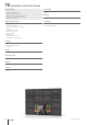
70 Information about the Series Key advantages § § § § § Full-face illumination Excellent tactile feedback Almost limitless design possibilities Easy-to-clean, UV-resistant films PCB mount switches Typical application areas § § § § § § § § § § Machinery Public transportation Heavy duty and special vehicles Marine Telecommunications Medical technology Energy supply Automation Building infrastructure Food and beverage industry Lens Material § Plastic Markings § Printed insert film legends Conformities
Index 70 PCB Switching element without illumination 802 Switching element with illumination 804 Indicator element 806 Components 808 Accessories 810 Technical data 811 Application Guidelines 813 01 02 03 04 09 14 17 18 19 22 31 41 45 51 56 57 61 70 71 82 84 92 96 06/2019 § eao.
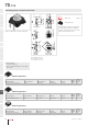
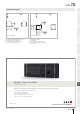
70 PCB 01 Switching element without illumination 9 02 3.5 3.5 Equipment consisting of (schematic overview) 1 12.5 03 A 04 Ø 7.9 Ø 1.6 Spacer cap 4.3 Switching element 5 1.5 12 x 12 1.2 3.8 x 3.8 3 Product can differ from the current configuration. 14 To obtain a complete unit, please select the red components from the pages shown. B 3 4.5 3.6 C 19 1 4 2 12.5 18 16 .8 1.8 3 1 5.08 4 22 3.8 x 3.8 17 7.5 12.8 x 12.8 Dimensions [mm] A = For Part No. 70-100.
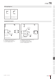
PCB 70 Wiring diagrams 01 3 4 3 4 1 2 1 2 02 03 04 Wiring diagram 331 Wiring diagram 332 09 Component layouts A 14 A C 17 C B B 18 Ø2.0 (2x) C C 1 2 3 4 C B C B C C 5.08 C 9.00 C 5.08 D 1 2 3 4 19 22 Ø1.3 (4x) 12.70 D Component layout 79 Dimensions [mm] A = Switching element without illumination B = Drilling plan (component side) C = Occupancy plan (component side) D = Hole for switching element Ø1.3 (4x) 12.
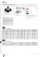
70 PCB 01 Switching element with illumination Ø8 22 9.3 4 19 12.5 4 Single-LED Switching element .8 18 3 Page 808 Product can differ from the current configuration. Each Part Number listed below includes all the black components shown in the 3D-drawing. Dimensions [mm] 14 17 2 16 09 1 10.16 04 Lens 1 3.6 12.5 5.08 03 5.7 Equipment consisting of (schematic overview) 02 To obtain a complete unit, please select the red components from the pages shown.
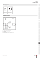
PCB 70 Wiring diagrams 01 3 4 3 4 + 1 2 1 2 – 02 03 04 Wiring diagram 332 Wiring diagram 333 09 Component layouts A 14 17 C B 18 Ø1.3 (4x) 19 10.16 D B C C K 1 C C B 3 10.16 Ø1.0 (2x) 12.70 E 2 4 A 22 31 Component layout 82 41 Dimensions [mm] A = Switching element with illumination B = Single LED C = Drilling plan (component side) D = Hole for switching element, Pad max. Ø 2.5 mm E = Hole for LED 45 51 56 57 61 70 71 82 84 92 96 06/2019 § eao.
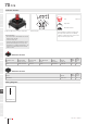
70 PCB Indicator element Equipment consisting of (schematic overview) 4 1.6 02 5.7 01 Lens 03 .8 8 0. 16 Page 808 8 0. 6.35 x 04 Single-LED 12.5 09 14 17 18 19 Product can differ from the current configuration. Illumination element Dimensions [mm] Each Part Number listed below includes all the black components shown in the 3D-drawing. General information To obtain a complete unit, please select the red components from the pages shown.
PCB 70 Component layouts A 01 A C B 02 C B 03 C 2 3 4 Ø1.3 (4x) 12.70 04 D B 6.35 C 1 10.16 C 5.08 Ø1.0 (2x) C K C B C 09 A D Component layout 79 Dimensions [mm] A = Switching element without illumination B = Drilling plan (component side) C = Occupancy plan (component side) D = Hole for switching element 6.35 Ø1.0 (2x) 10.
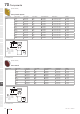
70 Components {$d=Druckhaube} 01 02 03 Lens plastic square Lens material Lens colour Lens optics Lens shape Lens illumination Dimensions Part No. Plastic White translucent flush illuminative 19.05 mm x 19.05 mm 70-920.9 Red translucent flush illuminative 15,4 mm x 15,4 mm 70-921.2 Orange translucent flush illuminative 15,4 mm x 15,4 mm 70-921.3 Yellow translucent flush illuminative 15,4 mm x 15,4 mm 70-921.
Components 70 {$d=Single-LED} 01 02 Single-LED, T1 3/4 MG Illumination colour Lumi. Intensity Dom. Wavelength Forward voltage Part No. Wiring diagram Red 160 mcd 625 nm 2.0 VDC @ 20 mA 10-2601.3172S 70 Amber 165 mcd 605 nm 2.0 VDC @ 20 mA 10-2601.3173S 70 Yellow 600 mcd 580 nm 2.9 VDC @ 20 mA 10-2603.3174S 70 Green 650 mcd 525 nm 3.2 VDC @ 20 mA 10-2603.3175S 70 Blue 250 mcd 467 nm 3.0 VDC @ 20 mA 10-2603.3176S 70 White 500 mcd x: 0.31 / y: 0.32 nm 3.
70 Accessories 01 Front side 02 03 04 Spacing cap Product attributes Dimensions Part No. Without recesses for LED 18.9 mm 70-901.0 2 recesses for LED 9 mm 70-910.0 13 mm 70-911.0 22.5 mm 70-912.0 09 14 20/20/19.05 min. 6. 2 6 6 17 18 16/16/15 H=9/13/22.5 19 18 min. 22 31 41 14 H=18.9 Dimensions [mm] 45 51 56 57 61 70 71 82 84 92 96 810 eao.
Technical data 70 Switching element illuminated Part No. 92-851.342 01 Switching system Electrical characteristics Short-travel switching system with two independent contact points and tactile operation. Guarantees reliable switching even of very light loads 1 normally open contact Electrical life 02 ≥ 500 000 cycles of operation at 42 VDC, 50 mA, as per IEC 60512-5-9c When attention is paid to the direction of current flow from terminal 3/4 to 1/2 the electrical life can be prolonged.
70 Technical data 01 02 03 04 Electrical characteristics Ambient conditions Electrical life Storage temperature at 5 VDC, 1 mA 500 000 cycles of operation – 30 °C … + 85 °C Switching voltage and switching current Operating temperature Max. 12 VDC, 50 mA Min. 1 VDC, 10 mA – 20 °C … + 70 °C Electric strength Approvals 250 VAC for 1 minute 09 Conformities CE 2011 / 65 / EC (RoHS) 14 17 18 19 22 31 Switching element non-illuminated Part No. 70-201.
Application Guidelines 70 Suppressor circuits 01 When switching inductive loads such as relays, DC motors, and DC solenoids, it is always important to absorb surges (e. g. with a diode) to protect the contacts. When these inductive loads are switched off, a counter emf can severely damage switch contacts and greatly shorten lifetime. Fig. 1 shows an inductive load with a free-wheeling diode connected in parallel.
70 Application Guidelines 01 Temperature curve wave soldering 02 03 04 09 14 17 Green curve: Red curve: Temperature on the component side of the pcb Temperature on the soldering side of the pcb Room temperature: Temp 1 19 Preheating: Temperature process = Temp 1 … Temp 2 Process time = t1 … t2 22 Ramp up to soldering temperature: Process time = 31 Soldering phase: 18 41 45 51 56 57 61 70 t2 … t3 Temperature process = Temp 3 Process time = t3 … t4 Iron soldering Basic specification for iro