
Datasheet

Component layouts
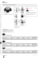
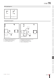
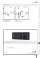
Component layout 79
Dimensions [mm]
A = Switching element without illumination
B = Drilling plan (component side)
C = Occupancy plan (component side)
D = Hole for switching element
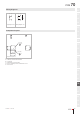
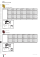
Component layout 81
Dimensions [mm]
A = Illumination element
B = Single LED
C = Drilling plan (component side)
D = Hole for centering pins non-metallic
E = Hole for LED
PCB
www.eao.com/70
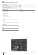
Proven in customer-specifi c membrane applications – thanks to almost limitless design possibilities.
.
Long-standing HMI System competence
.
Homogeneous illumination
.
Excellent tactile feedback
.
Almost limitless design possibilities
.
Easy-to-clean, UV-resistant lms
Flexible. Tactile and reliable.
EAO Series 70.
06/2019 § eao.com
807
70
01
02
03
04
09
14
17
18
19
22
31
41
45
51
56
57
61
70
71
82
84
92
96
12.70
C
C
C
C
1
3
2
4
Ø1.3 (4x)
5.08
D
B
A
C
6.35
10.16
6.35
10.16
C
C
B
B
A
K
Ø1.0 (2x)
Ø1.0 (2x)
B
D
E
A
C