
Datasheet

Pushbutton ring illumination PCB standard, IP67
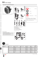
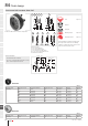
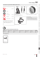
Equipment consisting of (schematic overview)
Lens Page 914
Actuator
Fixing nut
Mountingange Page 928
Single-LED Page 918
Switching element Page 919
Each Part Number listed below includes all the
black components shown in the 3D-drawing.
To obtain a complete unit, please select the red
components from the pages shown.
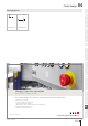
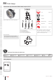
Dimensions [mm]
E = Lens raised above bezel
G = Lens convexe raised above bezel
Product can differ from the current conguration.
Mounting cut-outs [mm]
General information
• Front bezel illuminated
• Accessories for halo illumination: Essential len-
ses Part No. 84-7202.x00A and 84-7205.x00A
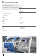
Actuator, Front dimension Ø 25 mm
Switching action Front bezel colour Front bezel material IP front protection Front bezel optics Part No.
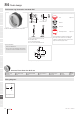
Wiring
diagram
Momentary White Plastic IP67 translucent 84-1091.7 294
Wiring diagrams
Wiring diagram 294
Flush design
01/2019 § eao.com
897
84
01
02
03
04
09
14
17
18
19
22
31
41
45
51
56
57
61
70
71
82
84
92
96
7
4
Ø25
4
max.
3.618
2
G GEE
NJO
PLQ
±
3NBY
x2+
x1-