
Datasheet
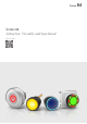

Pushbutton ring illumination standard, IP67
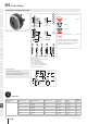
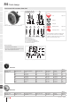
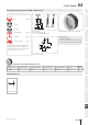
Equipment consisting of (schematic overview)
Lens Page 914
Actuator
Fixing nut
Switching element Page 919
Each Part Number listed below includes all the
black components shown in the 3D-drawing.
To obtain a complete unit, please select the red
components from the pages shown.
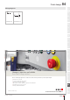
Dimensions [mm]
A = Plug-in terminal 2.8 mm x 0.5 mm
B = Flat ribbon cable
E = Lens raised above bezel
G = Lens convexe raised above bezel
Product can differ from the current conguration.
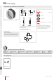
Mounting cut-outs [mm]
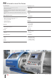
General information
• Front bezel illuminated
• Accessories for halo illumination: Essential len-
ses Part No. 84-7202.x00A and 84-7205.x00A
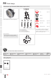
Actuator, Front dimension Ø 25 mm
Switching action Front bezel colour Front bezel material IP front protection Front bezel optics Part No.
Wiring
diagram
Momentary White Plastic IP67 translucent 84-1091.7 294
Wiring diagrams
Wiring diagram 294
Flush design
eao.com § 01/2019
896
84
01
02
03
04
09
14
17
18
19
22
31
41
45
51
56
57
61
70
71
82
84
92
96
Ø25
7
6 max.
2
4
23
9
23
300
±10
A
B
E
E G
G
NJO
PLQ
±
3NBY
x2+
x1-