
Product Manual


Instruction Sheet
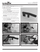
Hiller/Furrower Kit with Adapters
Check for parts online at www.getearthquake.com or call 800-345-6007 M-F 8-5
15683 HILLER/FURROWER KIT (OPTIONAL ACCESSORY)
Thank you for purchasing a hiller/furrower attachment for your rototiller. We know that you will be pleased with the many uses
you can accomplish with this handy tool.
PARTS BREAKDOWN
P/N: 25133
ECN: 11711
REV2: 06/20/17
© 2017 Ardisam, Inc.
All Rights Reserved
All weights, specications and features are approximate and are subject to change without notice. Due to continuous product
improvements, product images may not be exact. Items used for props not included. Some assembly may be required.
KEY # PART # DESCRIPTION QT Y.
16513 BRACKET HILLER/FURROWER RED 1
2 16514 WING LEFT HILLER/FURROWER RED 1
3 16515 WING RIGHT HILLER/FURROWER RED 1
4 16516 SHOVEL HILLER/FURROWER RED 1
5 20143 WASHER M8 X 16 X 1.5 MM GR8.8 ZN 4
6 21247 BOLT M10 X 1.5 X 30 MM HHCS GR8.8
ZN
2
7 21810 WASHER M8 EXTERNAL TOOTH LOCK 4
23204 NUT M8 X 1.25 MM W GR8 ZN 4
9 23205 BOLT M8 X 1.25 X 20 MM CRG GR8
ZN FT
4
KEY # PART # DESCRIPTION QT Y.
10 23206 BOLT M10 X 1.5 X 40 MM CRG GR8
ZN FT
2
11
W1265V0903
NUT M10 HNYLK GR8.8 ZN 4
- 25126 HILLER ADAPTER HUSQVARNA 1
- 25127 HILLER ADAPTER SOUTHLAND/
POWERMATE
1
- 25128 HILLER ADAPTER TROYBILT/
CUB CADET
1
9
3
8
7
5
6
1
11
2
4
10
INSTALLATION
1. Attach the bracket (1) to the shovel (4) using two M10 x 40mm carriage bolts (10) and M10 locknuts (11).
NOTE: The M10 carriage bolts (10) are installed from the front of the shovel (4), while the bracket (1) is installed from the
back of the shovel (4).
2. Align the curved slots of the left wing (2) with the square holes on the left side of the shovel (4). The small bend of the left
wing (2) should be facing up. Using two M8 x 20mm carriage bolts (9), at washers (5), external tooth washers (7), and wing
nuts (8), secure the left wing (2) to the shovel (4). Repeat step to install the right wing (3).
NOTE: Adjust the left and right wing (2, 3) to the correct hill size before tightening the wing nuts (8).
3. Remove two carriage bolts (A) that hold the tail to the tine shield. Slide the slotted end of the bracket (1) over drag stake
mount (under the tail hood of your tiller).
4. Align the holes in the bracket (1) with the single hole in the middle of the drag stake mount. Using the M10 x 30mm bolt (6)
and a M10 locknut (11), secure the hiller/furrower to the tiller.
NOTE: There is an extra M10 x 30mm bolt (6) and M10 locknut (11) that is used for the 25127 adapter only.
5. Re-attach the tail to the tine shield.
A