ENGLISH Operator Manual CHIPPER SHREDDER 50:1 SERIAL NO. DATE OF PURCHASE: THIS INSTRUCTION BOOKLET CONTAINS IMPORTANT SAFETY INFORMATION. PLEASE READ AND KEEP FOR FUTURE REFERENCE. Get parts or technical assistance online at www.GetEarthquake.
Operator Manual CHIPPER SHREDDER STOP! ACTIVATE YOUR WARRANTY BEFORE USE All products must be registered within 30 days from the date of purchase in order to be covered under warranty. For more information regarding Warranty and Registration please review the Warranty and Registration terms and conditions expressed in the warranty insert. INTRODUCTION Thank you for purchasing your product from Earthquake®. We have worked to ensure that this product meets the highest standards for usability and durability.
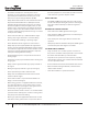
Operator Manual CHIPPER SHREDDER BOLT IDENTIFICATION CHART Bolts shown are for size reference only. Extra hardware may be included in the parts bag. (A) M8 x 40 MM Bolt Qty 4 (B) M8 x 20 MM Flange Bolt Qty 4 (G) M8 Nut Qty 8 (H) M8 Nyloc Nut Qty 3 (I) M6 Nut Qty 3 (C) M6 x 16 MM Bolt Qty 3 TOOLS NEEDED - NOT INCLUDED (D) 12 X 24 MM Washer Qty 2 (E) M8 Washer Qty 12 8 MM Wrench - Qty 1 10 MM Wrench - Qty 1 (F) M6 Spring Lock Washer Qty 3 Get parts online at www.GetEarthquake.
Operator Manual CHIPPER SHREDDER WARNINGS AND SAFETY PRECAUTIONS OWNER’S RESPONSIBILITY Accurate assembly and safe and effective use of the machine is the owner’s responsibility. • Read and follow all safety instructions. • Carefully follow all assembly instructions. • Maintain the machine according to directions and schedule included in this Earthquake® operator manual. • Ensure that anyone who uses the machine is familiar with all controls and safety precautions.
Operator Manual CHIPPER SHREDDER GENERAL OPERATING SAFETY • • DANGER Read the operating and service instruction manual carefully. Be throughly familiar with the controls and the proper use of the equipment. Know how to stop the unit and disengage the controls quickly. THE CHIPPER SHREDDER HAS SPINNING BLADES THAT CAN AMPUTATE HANDS AND FEET. DO NOT PLACE HANDS OR FEET IN THE HOPPER OR CHIPPER CONE, OR DISCHARGE CHUTE.
Operator Manual CHIPPER SHREDDER • Do not operate without the debris bag in place because this unit discharges debris at high speeds. If the unit is operated on hard ground, asphalt, concrete, or other hard surfaces without the collection bag in place. Material can ricochet off of the hard surface and cause an unsafe condition for users and bystanders. • Always obey the size limitations for tree limbs and branches stated in the Waste Materials Guide portion of this manual.
Operator Manual CHIPPER SHREDDER ENGINE SPECIFIC SAFETY • • WARNING Before cleaning, repairing, or inspecting, shut off the engine and make certain that all moving parts have come to a complete stop. Disconnect the spark plug wire and secure the wire away from the spark plug to prevent accidental starting. ENGINE GIVES OFF CARBON MONOXIDE, AN ODORLESS, COLORLESS, POISON GAS. CARBON MONOXIDE MAY BE PRESENT EVEN IF YOU DO NOT SMELL OR SEE ANY ENGINE EXHAUST.
Operator Manual CHIPPER SHREDDER • • Prevent fire and explosion caused by static electric discharge. Use only nonmetal, portable fuel containers approved by the Underwriter’s Laboratory (U.L.) or the American Society for Testing & Materials (ASTM). Always fill fuel tank outside in a well ventilated area. Never fill your fuel tank with fuel indoors. (Examples include: basement, garage, barn, shed, house, porch, etc.) Never fill tank near appliances with pilot lights, heaters, or other ignition sources.
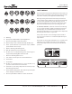
Operator Manual CHIPPER SHREDDER SAFETY DECALS A G B H M C I N D F This unit has been designed and manufactured to provide you with the safety and reliability you would expect from an industry leader in outdoor power equipment manufacturing.
Operator Manual CHIPPER SHREDDER FEATURES AND CONTROLS CONTROL FUNCTIONS The information below briefly describes the function of individual controls. Operating requires the combined use of several controls applied in specific sequences. To learn what combination and sequence of controls to use for various tasks see the OPERATION section. *For engine features and controls see engine manual.
Operator Manual CHIPPER SHREDDER SPECIFICATIONS Model # 33968 33964 Chipping Capacity Approx. 3” Approx. 3” Shredding Capacity 1/2” x 18” long 1/2” x 18” long 2 2 2 J-Hammers, 2 TriangleHammers 2 J-Hammers, 2 TriangleHammers 20:1 20:1 Start Type Recoil Recoil Rotor Material Steel Steel 16.75” x 13.25” 16.75” x 13.
Operator Manual CHIPPER SHREDDER UNPACKING AND ASSEMBLY G CARTON CONTENTS ASSEMBLY • Manual Parts Bag • Hardware Parts Bag: • A - (4) M8 x 40 MM Bolts (for 33968) • WHEEL AXLE (4) M10 x 50 MM Bolts (for 33964) • B - (4) M8 x 20 MM Bolts • D - (2) 12 x 24 MM Washers • E - (12) M8 Washers (for 33968) • (4) M8 Washers (for 33964) • E A KICKSTAND (8) M10 Washers (for 33964) • G - (8) M8 Nuts (for 33968) • (4) M8 Nuts (for 33964) • (4) M10 Nuts (for 33964) • H - (3) M8 Nyloc Nuts • I
Operator Manual CHIPPER SHREDDER DAMPER I STUD PLATE CHIPPER CONE H Position the chipper cone over the three M8 x1.25 threaded studs protruding from the engine plate, and attach using three M8 nyloc nuts (H). Rotate cone and cone base away from engine so cone does not contact engine. Tighten the three M8 nyloc nuts (H) securely. Remove back four M6 nuts (I) and set nuts and rear stud plate aside. Loosen front four M6 nuts (I). Note: These will not need to removed.
Operator Manual CHIPPER SHREDDER HOPPER HANDLE G E BRACKET B SUPPORT ROD TAB Hold the hopper handle up so that the outer holes in the handle align with the holes in the hopper and secure with four M8 x 20 MM bolts (B), four M8 washers (E) and four M8 nuts (G). Insert the screws from the outside of the hopper. Slide the support rod into the bracket. Rotate the rod so that it sits below the front tab of the bracket. FIGURE 6 TABS Slide the tabs on the debris bag onto the support rod.
Operator Manual CHIPPER SHREDDER OPERATION DANGER Be sure to read all information in the Safety and Operation section before attempting to operate this unit. Become familiar with all of the controls and how to stop the unit. THE EXHAUST FROM THIS PRODUCT CONTAINS CARBON MONOXIDE GAS. CARBON MONOXIDE IS A COLORLESS, ORDERLESS AND TASTELESS GAS THAT CAN CAUSE DIZZINESS, NAUSEA, UNCONSCIOUSNESS OR EVEN BRAIN DAMAGE AND DEATH IF INHALED FOR PROLONGED PERIODS.
Operator Manual CHIPPER SHREDDER CHIPPING TIPS: SHREDDING TIPS: • Prune branches down close to the main branch to make feeding them into the chipper cone easier. • Don’t overload the shredder by dumping large volumes of material into the hopper opening. • Large, hard, dried tree branches that resist chipping can be processed by rotating them as you alternately insert and retract them. • Alternate loads of wet and dry material to prevent the discharge from becoming plugged.
Operator Manual CHIPPER SHREDDER TRANSPORTING AND STORAGE MAINTENANCE • Always observe safe refueling and fuel handling practices when refueling the unit after transportation or storage. SCHEDULE AND PROCEDURES • Never store the unit (with fuel) in an enclosed, poorly ventilated structure. Fuel vapors can travel to an ignition source (such as a furnace, water heater, etc.) and cause an explosion. Fuel vapor is also toxic to humans and animals.
Operator Manual CHIPPER SHREDDER CHECK FOR LOOSE HARDWARE Service Interval: Every 5 hours; every spring and fall. Inspect the unit, checking for loose hardware or components. Pay special attention to the hardware attaching the chipper cone, hopper, axle, and front leg. AIR SHROUD INTAKE/ AIR FILTER MUFFLER DEBRIS OFTEN GATHERS IN THIS AREA CHECK SAFETY LABELS Service Interval: Every spring and fall. Check that the safety labels are in place and undamaged. Replace any damaged or missing decals.
Operator Manual CHIPPER SHREDDER INSPECT CHIPPING KNIVES Service Interval: Every 25 hours, or as necessary CAUTION The chipping knives of this unit can be rotated or sharpened to provide a new cutting surface as required. When inspecting the knives be careful to avoid touching the sharpened edges. To inspect the chipping knives: FOR THE SAFETY OF THE USER, AND TO MAXIMIZE THE LIFE OF THE ENGINE, IT IS CRUCIAL TO TAKE TIME TO CHECK THE CONDITION OF THE ENGINE. PROBLEMS MUST BE CORRECTED BEFORE OPERATING.
Operator Manual CHIPPER SHREDDER TROUBLESHOOTING While normal care and regular maintenance will extend the life of your equipment, prolonged or constant use may eventually require that service be performed to allow it to continue operating properly. The troubleshooting guide below lists the most common problems, their causes, and remedies.
Operator Manual CHIPPER SHREDDER REPAIR WARNING ROTOR REMOVAL NOTE: The rotor does not need to be removed to change the hammers and knives. However, the removal and installation of the knives will be easier with the rotor removed. CUTTING HAZARD. TO AVOID SERIOUS INJURY, AVOID CONTACTING THE SHARP CUTTING EDGES OF THE CHIPPING KNIVES. NOTE: If using a unit that has socket head bolts with no locking plates on them, the hardware will need to be upgraded to new hardware kit.
Operator Manual CHIPPER SHREDDER opposite side of the rotor faces outward for balanced rotation. Two faces of the bolt should align in parallel with the lock plate tabs. NOTE: We recommend the use of high-strength thread locker on mounting bolts. 4. 5. Bend the lock plate tabs up to secure the bolt and preventing rotation. The tabs should sit flat on a face of the bolt. SEE FIGURE 18. LOCK PLATE TABS Repeat for all hammers.
Operator Manual CHIPPER SHREDDER NOTES: Get parts online at www.GetEarthquake.
ARDISAM, INC. 1160 Eighth Avenue PO Box 666 Cumberland, WI 54829 Phone: (800) 345-6007 Fax: (715) 822-2124 www.getearthquake.
BROYEUSE-DÉCHIQUETEUSE Modèles n° : 33968, 33964 N° DE SÉRIE DATE D’ACHAT : CE LIVRET D’INSTRUCTIONS CONTIENT DES INFORMATIONS IMPORTANTES SUR LA SÉCURITÉ. VEUILLEZ LE LIRE ET LE CONSERVER POUR TOUTE CONSULTATION EXTÉRIEURE. Pièces détachées et assistance technique en ligne à www.GetEarthquake.
Manuel de l’utilisateur BROYEUSE-DÉCHIQUETEUSE ARRÊTEZ! ACTIVEZ LA GARANTIE AVANT UTILISATION ARRÊTEZ! Tous les produits doivent être enregistrés dans les 30 jours à compter de la date d’achat pour être couverts par la garantie. Pour plus d’information sur la garantie et l’enregistrement, veuillez consulter les modalités et conditions de la garantie et de l’enregistrement figurant dans l’encart de garantie. INTRODUCTION Merci d’avoir acheté ce produit Earthquake®.
Manuel de l’utilisateur BROYEUSE-DÉCHIQUETEUSE SCHÉMA D’IDENTIFICATION DES VIS Vis représentées à des fins de référence de taille seulement. Le sachet de pièces peut contenir de la visserie supplémentaire.
Manuel de l’utilisateur BROYEUSE-DÉCHIQUETEUSE AVERTISSEMENTS ET MESURES DE PRÉCAUTION RESPONSABILITÉ DU PROPRIÉTAIRE L’assemblage correct et l’utilisation sûre et efficace de la machine relèvent de la responsabilité de l’utilisateur. • Lire et respecter toutes les instructions de sécurité. • Suivre avec attention toutes les instructions d’assemblage. • Entretenir la machine conformément aux instructions et au calendrier figurant dans le manuel de l’utilisateur Earthquake®.
Manuel de l’utilisateur BROYEUSE-DÉCHIQUETEUSE CONSIGNES GÉNÉRALES DE SÉCURITÉ • • DANGER Lire le manuel d’instructions d’utilisation et d’entretien avec attention. Veiller à bien se familiariser avec les commandes et la bonne utilisation de la machine. Veiller à savoir comment arrêter la machine et débrayer les commandes rapidement. LA BROYEUSE-DÉCHIQUETEUSE COMPORTE DES LAMES EN ROTATION CAPABLES D’AMPUTER LES MAINS ET LES PIEDS.
Manuel de l’utilisateur BROYEUSE-DÉCHIQUETEUSE • Ne pas faire fonctionner la machine sans son sac collecteur car elle éjecte les déchets à des vitesses élevées. Si la machine est utilisée sur de la terre battue, de l’asphalte, du béton ou d’autres surfaces en dur sans le sac collecteur en place, la matière peut ricocher sur la surface dure et présenter des risques pour les utilisateurs et autres personnes présentes.
Manuel de l’utilisateur BROYEUSE-DÉCHIQUETEUSE MESURES DE SÉCURITÉ PROPRES AU MOTEUR • • AVERTISSEMENT Avant tout nettoyage, réparation ou contrôle de la machine, arrêter le moteur et s’assurer que toutes les pièces en mouvement soient à l’arrêt complet. Débrancher le câble de la bougie et l’attacher à l’écart de la bougie pour éviter tout démarrage accidentel. LE MOTEUR THERMIQUE DÉGAGE DU MONOXYDE DE CARBONE, UN GAZ TOXIQUE INODORE ET INCOLORE.
Manuel de l’utilisateur BROYEUSE-DÉCHIQUETEUSE FEUX D’ESSENCE ET MANIPULATION SÉCURITAIRE DU CARBURANT • Entreposer l’essence ou une machine avec du carburant dans le réservoir à l’écart de chaudières, poêles, chauffe-eau et autres appareils électroménagers comportant une veilleuse ou autre source d’inflammation susceptible d’enflammer les vapeurs d’essence. • Ne jamais remplir les récipients à l’intérieur d’un véhicule ou sur un plateau de camion à doublure en plastique.
Manuel de l’utilisateur BROYEUSE-DÉCHIQUETEUSE AUTOCOLLANTS DE SÉCURITÉ A G B C H I M N D J E K O F L P Cette machine est conçue et fabriquée pour offrir toute la sécurité et la fiabilité qu’on est en droit d’attendre d’un leader du marché de l’outillage motorisé pour travaux extérieurs.
Manuel de l’utilisateur BROYEUSE-DÉCHIQUETEUSE CARACTÉRISTIQUES ET COMMANDES FONCTIONS DE COMMANDE L’information ci-dessous décrit brièvement la fonction des commandes individuelles. L’utilisation suppose une utilisation combinée de plusieurs commandes actionnées dans des ordres particuliers. Pour savoir quelle combinaison de commandes utiliser et dans quel ordre pour les diverses tâches, voir le chapitre UTILISATION. *Voir les caractéristiques et commandes du moteur dans le manuel de moteur.
Manuel de l’utilisateur BROYEUSE-DÉCHIQUETEUSE DONNÉES TECHNIQUES N° de modèle 33968 33964 Capacité de déchiquetage Env. 7,6 cm (3 po) Env.
Manuel de l’utilisateur BROYEUSE-DÉCHIQUETEUSE DÉBALLAGE ET ASSEMBLAGE G CONTENU DU CARTON D’EMBALLAGE MOTOCULTEUR • Sachet de documentation : • Sachet de pièces : • A - (4) Vis M8 x 40 mm (33968) • AXE DE ROUES (4) Vis M10 x 50 mm (33964) • B - (4) Vis M8 x 20 mm • D - (2) Rondelles 12 x 24 mm • E - (12) Rondelles M8 (33968) • E A BÉQUILLE (4) Rondelles M8 (33964) • (8) Rondelles M10 (33964) • G - (8) Écrous M8 (33968) • (4) Écrous M8 (33964) • (4) Écrous M10 (33964) • H - (3) É
Manuel de l’utilisateur BROYEUSE-DÉCHIQUETEUSE CLAPET CÔNE DE DÉCHIQUETEUSE I PLAQUE À GOUJONS H Placer le cône de déchiqueteuse sur les trois goujons filetés M8 x 1,25 po qui dépassent de la plaque du moteur et l’attacher avec trois écrous autobloquants M8 (H). Pivoter le cône et sa base à l’écart du moteur de telle façon que le cône ne touche pas le moteur. Serrer fermement les trois écrous autobloquants M8 (H).
Manuel de l’utilisateur BROYEUSE-DÉCHIQUETEUSE GUIDON DE TRÉMIE G E ATTACHE DE FIXATION B TIGE-SUPPORT PATTE Tenir le guidon de trémie de façon à aligner les trous extérieurs du guidon sur les trous de la trémie et attacher avec quatre vis M8 x 20 mm (B), quatre rondelles M8 (E) et de quatre écrous M8 (G). Enfiler les vis par l’extérieur de la trémie. FIGURE 6 Engager la tige-support dans l’attache de fixation. Faire pivoter la tige de telle façon qu’elle se trouve sous la patte avant de l’attache.
Manuel de l’utilisateur BROYEUSE-DÉCHIQUETEUSE UTILISATION DANGER Veiller bien à lire toute l’information de la section Sécurité et utilisation avant d’essayer de faire fonctionner cette machine. Veiller à se familiariser avec toutes les commandes et avec la façon d’arrêter la machine. L’ÉCHAPPEMENT DE CE PRODUIT CONTIENT DU MONOXYDE DE CARBONE GAZEUX.
Manuel de l’utilisateur BROYEUSE-DÉCHIQUETEUSE faciliter leur introduction dans le cône de déchiqueteuse. • Pour réduire les grandes branches d’arbre dures et sèches qui résistent au déchiquetage, les tourner progressivement en les introduisant et les retirant d’un mouvement de va-et-vient. • Si la matière à déchiqueter est extrêmement dure, produits des reculs violents lorsqu’on l’introduit dans le cône de déchiqueteuse ou est difficile à maîtriser, la sortir immédiatement et la mettre de côté.
Manuel de l’utilisateur BROYEUSE-DÉCHIQUETEUSE TRANSPORT ET ENTREPOSAGE ENTRETIEN • CALENDRIER ET PROCÉDURES • • Toujours observer des pratiques sécuritaires de remplissage et de manipulation du carburant lorsqu’on refait le plein de la machine après son transport ou son entreposage. Ne jamais entreposer la machine (avec du carburant) dans une structure fermée mal aérée. Les vapeurs de carburant peuvent se propager jusqu’à une source d’inflammation (chaudière, chauffeeau, etc.
Manuel de l’utilisateur BROYEUSE-DÉCHIQUETEUSE VÉRIFIER LE SERRAGE DE LA VISSERIE Intervalle d’entretien : Toutes les 5 heures; chaque printemps et automne. Contrôler la machine, en vérifiant le bon serrage de la visserie et des pièces. Accorder une attention particulière à la visserie de fixation du cône de déchiqueteuse, de la trémie, de l’axe des roues et de la béquille avant.
Manuel de l’utilisateur BROYEUSE-DÉCHIQUETEUSE CONTRÔLE DES COUTEAUX DE DÉCHIQUETAGE Intervalle d’entretien : Toutes les 25 heures ou s’il y a lieu. La rotation ou l’affûtage des fléaux de broyage de la machine permet de fournir une nouvelle surface de coupe s’il y a lieu. Lors de l’inspection des couteaux, faire preuve de précaution pour éviter de toucher les arêtes tranchantes. Pour contrôler les couteaux de déchiquetage : 1. Débrancher le câble de bougie et l’attacher à l’écart de la bougie.
Manuel de l’utilisateur BROYEUSE-DÉCHIQUETEUSE DÉPANNAGE Si un soin normal et l’entretien courant contribueront à étendre la durée de service de la machine, une utilisation intensive ou constante peut finir par nécessiter des réparations pour lui permettre de continuer à fonctionner correctement. Le guide de dépannage ci-dessous présente les problèmes les plus courants, leurs causes et leurs solutions.
Manuel de l’utilisateur BROYEUSE-DÉCHIQUETEUSE RÉPARATION AVERTISSEMENT DÉPOSE DU ROTOR REMARQUE : Il n’est pas nécessaire de déposer le rotor pour changer les fléaux et les couteaux. Toutefois, le démontage et le remontage des fléaux sont plus faciles à effectuer si le rotor est déposé. RISQUE DE COUPURE. POUR ÉCARTER LE RISQUE BLESSURE GRAVE, ÉVITER DE TOUCHER LES BORDS TRANCHANTS AIGUISÉS DES COUTEAUX DE DÉCHIQUETAGE.
Manuel de l’utilisateur BROYEUSE-DÉCHIQUETEUSE 4. Plier les languettes de la plaquette-frein de façon à bloquer la vis et empêcher sa rotation. Les languettes doivent appuyer à plat sur une face de la tête de vis. VOIR FIGURE 18. 5. Répéter pour tous les fléaux. DÉMONTAGE ET REMONTAGE DES COUTEAUX DE DÉCHIQUETAGE Pour contrôler ou changer les couteaux de déchiquetage : 1. Déplier les languettes de plaquette-frein des vis de fixation des couteaux de déchiquetage. 2.
Manuel de l’utilisateur BROYEUSE-DÉCHIQUETEUSE NOTES : Pièces détachées en ligne à www.GetEarthquake.
ARDISAM, INC. 1160 Eighth Avenue PO Box 666 Cumberland, WI 54829 États-Unis Téléphone : (800) 345-6007 Télécopieur : (715) 822-2124 www.GetEarthquake.