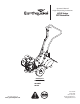
Operator’s Manual Original Operating Instructions 6015 Series CRT Rototiller Product #’s: 6015B (Shown) 6015BCE 6015V Get parts online at www.getearthquake.com GAS/OIL RATIO 50:1 P/N: 13594 ECN: 9543 Rev. 12/10/12 © 2013 Ardisam, Inc.
Operator’s Manual 6015 Series CRT Rototiller INTRODUCTION Congratulations on your investment in quality. Thank you for purchasing a 6015 Series CRT Rototiller from Earthquake™. We have worked to ensure that this tiller meets the highest standards for usability and durability. With proper care, your tiller will provide many years of service. Please read this entire manual before installation and use.
Operator’s Manual 6015 Series CRT Rototiller SAFETY DANGER OWNER’S RESPONSIBILITY DANGER INDICATES A SERIOUS INJURY OR FATALITY WILL RESULT IF THE SAFETY INSTRUCTIONS THAT FOLLOW THIS SIGNAL WORD ARE NOT OBEYED. Accurate assembly, and safe and effective use of the rototiller is the owner’s responsibility. • Read and follow all safety instructions. • Carefully follow all assembly instructions. • Maintain the tiller according to directions and schedule included in this Earthquake operator’s manual.
Operator’s Manual 6015 Series CRT Rototiller OPERATION IMPORTANT • Never operate the tiller without guards, covers and hoods in place. THE RIGHT AND LEFT SIDES OF YOUR ROTOTILLER ARE DETERMINED FROM THE OPERATING POSITION AS YOU FACE THE DIRECTION OF FORWARD TRAVEL. • Never start the engine or operate the tiller with the wheels in the free-wheel position. Make sure the wheel lock pins are engaged through the wheel hubs and wheel axle. The wheels act as a brake to keep the tiller at a controlled speed.
Operator’s Manual 6015 Series CRT Rototiller SAFETY DECALS This rototiller unit has been designed and manufactured to provide you with the safety and reliability you would expect from an industry leader in outdoor power equipment manufacturing.
Operator’s Manual 6015 Series CRT Rototiller UNPACKING AND ASSEMBLY Your rototiller comes fully assembled except for a few parts. The following instructions will help you unpack your tiller and assemble and adjust your tiller’s depth regulator lever, cable tension and handlebar height. You will need 2- 9/16” wrenches. UNPACK 1. Open top of carton and remove handlebar assembly. 2. Find parts packet.
Operator’s Manual 6015 Series CRT Rototiller ATTACH HANDLEBAR (6015BCE, EUROPE) handlebar extensions 1. Locate handlebar extensions. (SEE FIGURE 2) 2. Place handlebar extensions on outside of lower handlebar mount. Line up the handlebar extension pieces with the lower handlebar mount as shown in the decal located on the lower handlebar mount next to the mounting location. (SEE PAGE 21) 3. Insert one 3/8-16 x 1 3/4” bolt for each side in lower holes. Put 3/8” flat washers onto bolts. 4.
Operator’s Manual 6015 Series CRT Rototiller FEATURES (6015B Shown) handlebar forward drive safety control lever forward cable depth regulator lever detent pin choke tine hood side shield tines belt guard recoil start wheel lock pin on/off and throttle control 8 wheels Check for parts online at www.getearthquake.
Operator’s Manual 6015 Series CRT Rototiller OPERATION PRE-START INSPECTION 1. Make sure all safety guards are in place and all nuts and bolts are secure. 2. Check oil level in engine crankcase. See your engine manual for procedure and specifications. 3. Inspect air cleaner for cleanliness. See your engine manual for procedure. 4. Check the fuel supply. Fill the fuel tank no closer than 1 inch from top of tank to provide space for expansion. See your engine manual for fuel recommendations. 5.
Operator’s Manual 6015 Series CRT Rototiller START-UP The controls required to start and run the rototiller are located on the engine and are the choke and throttle levers. The choke lever is marked on one end with CHOKE and on the other with RUN. The throttle lever is marked on one end with a STOP icon and on the other with a FAST icon. There is also a SLOW icon next to STOP to indicate a low throttle position.
Operator’s Manual 6015 Series CRT Rototiller DRIVE SAFETY CONTROL LEVER Pull the drive safety control lever toward the handlebar to the FORWARD position to engage the wheels and tines. Releasing the lever into the NEUTRAL position stops the wheels and tines and brings the tiller to a complete stop. (SEE FIGURE 3) TILLING 1. Adjust the depth regulator lever to desired tilling depth. NOTE: Raise depth regulator lever up one hole at a time, testing tiller operation after each raise.
Operator’s Manual 6015 Series CRT Rototiller WHEEL LOCK PINS CAUTION To place wheels in free-wheel position: This allows wheels to turn freely on the axle for easy transportation. 1. Remove lock pin. Slide wheel inward toward machine. (SEE FIGURE 4) 2. Insert lock pin through the axle hole only, fold lock ring to secure pin to axle. 3. Repeat for other wheel. Place wheels in tilling position: This locks wheels to the axle so they are able to propel the machine forward while in use. 1. Remove lock pin.
Operator’s Manual 6015 Series CRT Rototiller DEPTH REGULATOR LEVER Tilling depth is controlled by the height of the depth regulator lever. To adjust tilling depth. (SEE FIGURE 6) 1. Remove detent pin. 2. Raise the depth regulator lever to position tines at chosen tilling depth. 3. Align hole in depth regulator lever with hole in depth regulator bracket and insert detent pin. WARNING DO NOT ADJUST TILLING DEPTH UNLESS DRIVE SAFETY CONTROL LEVER IS RELEASED TO NEUTRAL POSITION.
Operator’s Manual 6015 Series CRT Rototiller TILLING TIPS The key to successful tilling is to begin with a shallow cut on the first pass, and then work an inch or two deeper on each successive pass. • Tilling depth will vary with ground conditions. • When beginning to till in unbroken ground or in extremely hard soil, set the detent pin in the highest hole of the depth regulator lever (SEE PAGE 11). This will allow for shallow tilling.
Operator’s Manual 6015 Series CRT Rototiller MAINTENANCE MAINTENANCE SCHEDULE Your rototiller has been designed and produced by the industry’s leading manufacturer of outdoor power equipment to provide you years of reliable operation. Keeping your tiller in top running condition will prolong its life, and help you obtain optimum performance. Please read this normal care schedule, and note the recommended care operating intervals to extend the life of your unit.
Operator’s Manual 6015 Series CRT Rototiller CHANGE FORWARD BELT CAUTION 1. Turn off engine. Engine must be cool. 2. Remove spark plug wire and secure from spark plug. 3. Remove belt guard: (SEE FIGURE 8) - unscrew and remove guard rivet. DO NOT OPERATE TILLER BEFORE READING THE ENGINE MANUAL PROVIDED IN THE PARTS PACKET. WARNING - pull belt guard from machine. 4. Remove forward belt from engine pulley: (SEE FIGURE 9) - gently pull the engine recoil rope to rotate the pulley.
Operator’s Manual 6015 Series CRT Rototiller ENGINE MAINTENANCE Refer to the engine manual included in your parts packet for information on engine maintenance. Your engine manual provides detailed information and a maintenance schedule for performing the following tasks: 1. Check oil level before each use or after every 8 hours of operation. 2. Change oil after first 5-8 hours of operation. Change oil while engine is warm. Refill with new oil of recommended grade. 4.
Operator’s Manual 6015 Series CRT Rototiller STORAGE WARNING PREPARE FOR STORAGE Follow the steps below to prepare your tiller for storage. Read your engine manual for detailed instructions on preparing the engine for storage. 1. Protect wheels and axles from rust: DO NOT STORE TILLER IN AN UNVENTILATED AREA WHERE FUEL FUMES MAY REACH FLAME, SPARKS, PILOT LIGHTS OR AN IGNITED OBJECT. DRAIN FUEL OUTDOORS AWAY FROM ANY IGNITION SOURCES. USE ONLY APPROVED FUEL CONTAINERS.
Operator’s Manual 6015 Series CRT Rototiller TROUBLESHOOTING WARNING TROUBLESHOOTING GUIDE PRACTICE SAFETY AT ALL TIMES. ENGINE MUST BE TURNED OFF AND ALLOWED TO COOL, AND SPARK PLUG WIRE MUST BE DISCONNECTED AND SECURED BEFORE ATTEMPTING ANY MAINTENANCE OR REPAIR. While normal care and routine maintenance will extend the life of your rototiller, prolonged or constant use may eventually require that service be performed to allow it to continue operating properly.
Operator’s Manual 6015 Series CRT Rototiller CRT HANDLEBAR AND HOOD PARTS AND PARTS LIST (PRODUCT 6015V AND 6015B) 12 13 11 10 9 8 7 7 6 14 3 5 1 2 4 2 15 REF. NO. PART # DESCRIPTION QTY. 1 31305 WELDMENT, ENGINE/HANDLE MOUNT 1 REF. NO.
Operator’s Manual 6015 Series CRT Rototiller CRT HANDLEBAR AND HOOD PARTS AND PARTS LIST (PRODUCT 6015BCE) 12 11 13 10 9 8 7 6 14 3 5 4 1 2 15 REF. NO. PART # DESCRIPTION QTY. 1 31305 WELDMENT, ENGINE/HANDLE MOUNT 1 REF. NO.
Operator’s Manual 6015 Series CRT Rototiller CRT MOTOR MOUNT PARTS (PRODUCT 6015V) 5 4 35 3 2 38 34 6 8 3 7 2 3 1 14 29 39 2 11 33 32 28 36 37 30 31 13 10 9 12 15 3 16 17 19 17 18 19 3 20 21 22 15 21 23 27 23 21 26 19 25 22 24 Check for parts online at www.getearthquake.
Operator’s Manual 6015 Series CRT Rototiller CRT MOTOR MOUNT PARTS LIST (PRODUCT 6015V) R E F. PART # NO.
Operator’s Manual 6015 Series CRT Rototiller CRT MOTOR MOUNT PARTS (PRODUCT 6015B AND 6015BCE) 5 4 3 35 2 1 34 6 8 2 7 3 1 3 14 33 32 36 29 30 38 2 11 13 10 28 37 31 9 12 15 3 16 17 19 17 18 19 3 20 21 22 15 21 23 27 23 21 26 19 25 24 24 Check for parts online at www.getearthquake.
Operator’s Manual 6015 Series CRT Rototiller CRT MOTOR MOUNT PARTS LIST (PRODUCT 6015B AND 6015BCE) R E F. PART # NO. DESCRIPTION 1 810 BOLT, 5/16-24 X 1 HH GR5 2 504 3 4 QTY. R E F. PART # NO. DESCRIPTION QTY.
Operator’s Manual 6015 Series CRT Rototiller CRT TINES & HOOD PARTS (PRODUCT 6015V, 6015B AND 6015BCE) 1 2 3 23 20 21 26 4 21 5 23 6 22 4 11 8b 25 10 7 9 14 8a 19 15 4 18 2 17 24 16 12 7 11 14 13 26 Check for parts online at www.getearthquake.
Operator’s Manual 6015 Series CRT Rototiller CRT TINES & HOOD PARTS LIST (PRODUCT 6015V, 6015B AND 6015BCE) R E F . PART # NO. DESCRIPTION QTY.
Operator’s Manual 6015 Series CRT Rototiller CRT WHEEL & TILLER SHAFT PARTS & PARTS LIST (PRODUCT 6015V, 6015B AND 6015BCE) REF. NO. PART # DESCRIPTION 1 331063 BOLT, M6 X 25MM 2 1508 3 1507 4 --- 5 6 QTY. REF. NO.
Operator’s Manual 6015 Series CRT Rototiller NOTES Check for parts online at www.getearthquake.
Operator’s Manual 6015 Series CRT Rototiller 6015 SERIES CRT ROTOTILLERS Warranty Terms and Conditions PRODUCT WARRANTY: 1-YEAR LIMITED WARRANTY Ardisam, Inc., a manufacturing company, warrants this EARTHQUAKE CRT ROTOTILLER to be free from defects in the material or workmanship for a period of one year from the date of purchase. During the one-year warranty of this product, Ardisam will furnish, at their discretion, parts and labor to correct any defect caused by faulty material or workmanship.
Operator’s Manual 6015 Series CRT Rototiller Explanation of Emissions Control (6015V) Warranty Provisions Viper® Engines are designed, built and equipped to meet all EPA requirements. It warrants that it is free from defects in material and workmanship that could cause failure to the warranted part; and that it is identical in all material respects to the engine described in the manufacturer’s application for certification.
Earthquake™, Division of Ardisam, Inc. 1160 8th Avenue, PO Box 666 Cumberland, WI 54829 800-345-6007 | Fax 715-822-2223 E-mail: info@ardisam.com All weights, specifications and features are approximate and are subject to change without notice. Due to continuous product improvements, product images may not be exact. Items used for props not included. Some assembly may be required. Check for parts online at www.getearthquake.