Operator's Manual String Mower M200 SN GAS/OIL RATIO Includes Model: M200 Get parts online at www.getfieldsedge.com 50:1 P/N: 22230 ECN: 10789 REV1: 03/27/2015 © 2015 Ardisam, Inc.
Operator's Manual String Mower M200 INTRODUCTION Congratulations on your investment in quality. Thank you for purchasing an Fields Edge™ String Mower. We have worked to ensure that the string mower meets the highest standards for usability and durability. With proper care, your string mower will provide many years of service. Please read this entire manual before installation and use.
Operator's Manual String Mower M200 WARNINGS AND SAFETY PRECAUTIONS OWNER’S RESPONSIBILITY Accurate assembly and safe and effective use of the string mower is the owner’s responsibility. • Read and follow all safety instructions. • Carefully follow all assembly instructions. • Maintain the string mower according to directions and schedule included in this Fields Edge™ operator’s manual. • Ensure that anyone who uses the string mower is familiar with all controls and safety precautions.
Operator's Manual String Mower M200 GENERAL SAFETY RULES • • • • • • • • • • • • • • • • • 4 • Read, understand, and follow all instructions on the machine and in the manual(s). Be thoroughly familiar with the controls and the proper use of the mower before starting. Familiarize yourself with all of the safety and operating decals on this equipment and on any of its attachments or accessories. Do not put hands or feet near or under rotating parts.
Operator's Manual String Mower M200 SLOPE OPERATION • Engines give off carbon monoxide, an odorless, colorless, poison gas. Breathing carbon monoxide can cause nausea, fainting or death. Always start and run engine outdoors. Do not start or run engine in an enclosed area, even if doors or windows are open. • Never make adjustments or repairs with the engine (motor) running.
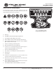
Operator's Manual String Mower M200 SAFETY DECALS AND WARNINGS Pictured below are safety and hazard symbols on the unit or in this manual. Before you operate your unit, learn and understand the purpose for each symbol. A B C D E F G H I J K L M N O Part No. LBLEQWARNSTRMR String Mower Warning Decal P A: Warning! B: Read Owner's Manual Before Operating Machine. C: Do Not Operate While Others Are Around. D: Remove Objects that Could Be Thrown By This Machine.
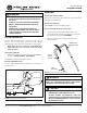
Operator's Manual String Mower M200 FEATURES Read this owner’s manual and safety rules before operating your mower. Take time to compare the following illustration with the mower to familiarize yourself with the product and its controls. SEE FIGURE 1 1 2 3 11 10 4 5 9 6 8 7 FIGURE 1: String Mower Features Specifications: 1. Mower Head Drive Lever - Engages rotation of Mower Head 2. Upper Handle Mower Line Diameter: 3. Engine ON/OFF Switch Mower Line Length: 4.
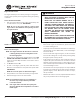
Operator's Manual String Mower M200 ASSEMBLY How to Raise the Handle Contents of Parts Bag 1. Hold the handle with one hand and loosen both handle adjustment cams until the ratchet teeth are disengaged. Do not remove the handle adjustment levers. 2. Raise the handle to the operating position. 3. Stand in the operator’s position behind the mower. Put the handle in a comfortable position. Make sure both sides of the handle are level.
Operator's Manual String Mower M200 OPERATION WARNING How to Stop the Mower Head • FOLLOW THE ENGINE MANUFACTURER’S INSTRUCTIONS FOR THE TYPE OF GASOLINE AND OIL TO USE. • ALWAYS USE A SAFETY GASOLINE CONTAINER. DO NOT SMOKE WHEN ADDING GASOLINE TO THE ENGINE. How to Stop the Engine WHEN INSIDE AN ENCLOSURE, DO NOT FILL WITH GASOLINE. BEFORE YOU ADD GASOLINE, STOP THE ENGINE. LET THE ENGINE COOL FOR SEVERAL MINUTES. How to Use the Mower Head Control Lever • Release the control lever.
Operator's Manual String Mower M200 Engine Throttle Control WARNING The engine throttle speed is a factory setting. It is designed to ensure proper speed of your string mower during all operating conditions. • How to Use the Primer Bulb DO NOT LEAVE THE STRING MOWER UNATTENDED WHILE THE ENGINE IS RUNNING. WAIT FOR THE MOWER LINES TO STOP ROTATING. • NEVER RUN THE ENGINE INDOORS OR IN A POORLY VENTILATED AREA. ENGINE EXHAUST CONTAINS CARBON MONOXIDE, AN ODORLESS AND DEADLY GAS.
Operator's Manual String Mower M200 MAINTENANCE, SERVICE, AND STORAGE NOTE: Maintenance, replacement or repair of the emissions control devices and systems may be performed by any non-road engine repair establishment or individuals. However, items must be serviced by an authorized dealer to obtain “no charge” emissions control service. Good maintenance is essential to help reduce air pollution and for safe, economical and trouble-free operation.
Operator's Manual String Mower M200 SERVICE AND ADJUSTMENT WARNING Be sure the engine is not operating and is located on a level surface before checking or refilling oil. Engine should be warm for easy removal of oil. 1. 2. 3. 4. Detach spark plug wire and move away from spark plug. If the engine uses a battery, disconnect at negative terminal. Remove dipstick and carefully tip the engine toward the dipstick side to empty oil from oil fill area.
Operator's Manual String Mower M200 MOWER HEAD SERVICE AND ADJUSTMENT, SLIDE-THROUGH VERSION ENTRANCE HOLE Replace Mower Line on Slide-Through Version For the best performance, use a heavy gauge (0.155" diameter) mower Cut the length of the mower line to 15". Use the length guide, located on the shield, to make sure the mower line is the correct length. Place one end of the mower line at location “A” and bend it along the raised portion of the shield. Cut line at location “B”.
Operator's Manual String Mower M200 How to Adjust the Height/Angle of the Handle WARNING Use the cam levers on each side of the handle to adjust the height of the handle. SEE FIGURE 18 1. Hold the handle with one hand and open both cam levers until the ratchet teeth are disengaged. Do not remove the nuts. 2. Move the handle up or down to the desired position, then align the ratchet teeth. Make sure both sides of the handle are level. 3. Tighten (lock) the lever.
Operator's Manual String Mower M200 with fresh gasoline in a separate container and add the mixture to the tank. Always follow the instructions on the stabilizer container. Run the engine at least ten minutes after stabilizer is added to allow the mixture to reach the carburetor. IMPORTANT TEST THE DRIVE SYSTEM. START THE ENGINE AND ENGAGE AND DISENGAGE THE MOWER HEAD SEVERAL TIMES. WHEN DISENGAGED, MAKE SURE THE MOWER HEAD COMPLETELY STOPS WHEN RESTING ON THE GROUND.
Operator's Manual String Mower M200 TROUBLESHOOTING GUIDE Trouble Engine does not start Cause Correction Spark plug wire disconnected Connect spark plug wire Engine not primed Prime engine Defective or incorrectly gapped spark plug Inspect or replace spark plug Fuel tank empty Add fuel Dirty carburetor or fuel line Clean carburetor or fuel line Dirty air filter Replace air filter Carburetor out of adjustment For carburetor adjustment, take the unit to an authorized service center Engine f
Operator's Manual String Mower M200 SLOPE GUIDE 15 DE SIGHT AND HOLD THIS GUIDE LEVEL WITH A VERTICAL TREE, A CORNER OF A STRUCTURE, A POWER LINE POLE, OR A FENCE. GREE S FOLD ALON G DO TTED LINE Operate a mower across the face of slopes, never up or down slopes 10 DEGREES Use this guide and do not mow on a slope greater than 15 degrees. A 10 degree slope is a hill that increases in height at approximately 1.76 feet in 10 feet.
Operator's Manual String Mower M200 PARTS BREAKDOWN 4 Handlebars 5 8 7 3 6 2 1 11 10 9 12 13 14 16 15 17 18 19 QTY. KEY PART # ZIP TIE 5.75 INCH BLACK 3 11 CLUTCH CABLE STRING MOWER 1 12 17528 CONTROL LEVER 1 17526 UPPER HANDLEBAR 1 17471 ON/OFF SWITCH STRING MOWER 6 W1265V0913 7 19939 8 9 10 KEY 18 DESCRIPTION QTY. 19973 RIVET M4 X 20 2 16397 SCREW M3 X 10 PHILIPS 8 13 16360 WASHER M3 X 0.
Operator's Manual String Mower M200 Engine and Pulley Attachment 1 2 9 3 4 5 6 7 8 KEY PART # DESCRIPTION 1 19922 BOLT M8 X 1.25 X 40 HEX 2 2 186000 ENGINE 173CC VIPER VERTICAL 1 3 W1265V0900 NUT M8 X 1.25 NYLOC 2 4 19971 KEY 4 X 4 X 20 MM 1 5 60005013 ENGINE PULLEY 1 6 331040 FLAT WASHER 10 X 32 X 4 MM 1 7 1916965 WASHER 3/8 INCH SPRING LOCK 1 8 1426 BOLT 3/8-16 X 1-1/4 HEX 1 9 19945 BOLT M8 X 1.25 X 20 HEX 1 Check for parts online at www.getfieldsedge.
Operator's Manual String Mower M200 Mower Head - Standard Version Mower Head - Slide-Through Version KEY PART # DESCRIPTION QTY. KEY PART # DESCRIPTION 1 16903 NUT M10 X 1.5 X 14 NYLOC HEX FLANGE 1 1 16903 NUT M10 X 1.5 X 14 NYLOC HEX FLANGE 1 2 16595 PULLEY ASSEMBLY STRING MOWER 1 2 16595 PULLEY ASSEMBLY STRING MOWER 1 3 19925 SPACER M17.5 X 23.5 X 6 1 3 19925 SPACER M17.5 X 25.
Operator's Manual String Mower M200 Base Unit 2 3 4 1 5 6 7 10 11 2 9 12 8 13 18 14 15 21 16 17 22 2 19 20 23 24 25 KEY PART # DESCRIPTION QTY. KEY PART # DESCRIPTION 1 19927 2 16903 3 QTY. BOLT M10 X 1.5 X 60 HEX 4 13 16400 NUT M8 X 1.0 NYLOC 4 NUT M10 X 1.5 X 13 NYLOC 5 14 19938 AXLE AND BRACKET ASSEMBLY 2 16889 SCREW 4.8 X 1.6 X 20 MM PHILIPS 2 15 19945 BOLT M8 X 1.25 X 20 HEX 4 4 19944 BUSHING M12 X 23 RUBBER 1 16 18898 WASHER M14 X 22 X 3.
Operator's Manual String Mower M200 NOTES _______________________________________________________________________________________________________ _______________________________________________________________________________________________________ _______________________________________________________________________________________________________ _______________________________________________________________________________________________________ ____________________________________________________
Operator's Manual String Mower M200 WARRANTY TERMS AND CONDITIONS PRODUCT WARRANTY: 5-YEAR LIMITED WARRANTY – 10/01/2014 Ardisam, Inc. (Ardisam), a manufacturing company, warrants this product to be free from defects in the material or workmanship for a period of five years from the date of purchase. If there is insufficient evidence of the purchase date, the effective date of this warranty will begin on the string mower’s date of manufacture.
Fields Edge™, Division of Ardisam, Inc. 1160 8th Avenue, PO Box 666 Cumberland, WI 54829 800-345-6007 | Fax 715-822-2223 E-mail: info@getfieldsedge.com All weights, specifications and features are approximate and are subject to change without notice. Due to continuous product improvements, product images may not be exact. Items used for props not included. Some assembly may be required. Check for parts online at www.getfieldsedge.