
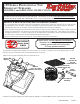
User Manual

PAGE 2
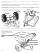
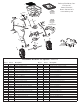
3. Lift the drAw bAr into position and replace the ¼-20 x 2 ¼” bolts washer and nut as shown below. Now tighten those bolts
and the other frame bolts.
4. Install drive wheel to the Axle using pin hole nearest to lower handles as shown. Insert 2” cotter pin through wheel and
through Axle. Bend with pliers to prevent pin from falling out.
5. Install CoASt wheel to Axle, using outside pin hole, insert the 1” cotter pin through Axle (not thru the wheel). Bend with
pliers to prevent pin from falling out.
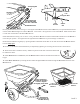
TURN SPREADER UPRIGHT ON TO WHEELS.
6. Remove the (2) ¼-20 x 1¾” bolts, washers, nuts, and pivot And brACket from the lower hAndleS as shown below.
7. Install Control Support ASSembly by sliding between lower hAndleS and inserting (2) 1¾” bolts thru the pivot brACket
and the lower hAndleS and secure
with (2) lock nuts and cupped washers
as shown below.
TIGHTEN ALL FASTENERS
NOW.
2” Cotter Pin
1” Cotter Pin
Remove Pivot Bracket
and ¼-20 x 1¾" Bolts,
cupped washers & lock nuts.
Slide the Control Assembly
into Lower Handles.
Next Replace Pivot Bracket
and ¼-20 x 1¾" Bolts, cupped
washers & lock nuts.
Rotate Draw
Bar up
Remove
bolts