
User Manual

0
30
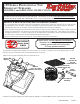
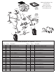
Slide Control Rod
into Pivot Bracket
then add ¼” Hex Nut
Calibration Point
Tensioning Nut
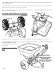
8. Next push lever forward to setting “0” now align Control rod with hole in pivot brACket, now pull lever backward to
insert Control rod through hole in pivot brACket. Now install ¼-20 regular nut on to Control rod. Make sure that there
is a Hex Nut on both sides of the pivot brACket tab.
9. Pull lever back to setting “30” as shown. Next, push pivot brACket forward so that the Shut-off plAte in the hopper is
in the full open position. Now tighten the nuts against the pivot brACket to prevent change in calibration.
Recheck the CAlibrAtion regularly by operating the flow Control lever back to #30 and check inside the hopper that the
holes are fully open.
10. Tension on the flow Control lever may be adjusted by tightening or loosening the tension nut as shown above.
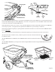
11. Ensure AgitAtor is installed correctly. Note: The position of at side of the AgitAtor should
be installed as shown.
12. Install debriS SCreen into hopper, slide the debriS SCreen under the extended bolt inside the
hopper.
13. Install drAw bAr hitCh by inserting the CleviS pin through the hitCh and then through the drAw bAr and secure with
hAir pin Clip
¼-20
Regular Nuts
Pivot
Bracket
Control
Rod
PAGE 3
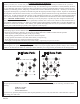
¼-20 x 1”
Hex Head Bolt
Stainless
¼-20 Lock Nut
Stainless
Attach Hitch
using Clevis Pin
and Hair Pin Clip
Select position to
so that the spreader
is level or angled
UP slightly at the back