EARTH WISE. The Glean Air Choice 4 OPERATOR’S MANUAL ELECTRIC LAWN MOWER United States Patent Pending 18 in. 50118 20 in. 50120 Your lawn mower has been engineered and manufactured to our high standard for dependability, ease of operation, and operator safety. Properly cared for, it will give you years of rugged, trouble-free performance. A WARNING: To reduce the risk of injury, the user must read and understand the operator's manual before using this product. Thank you for your purchase.
TABLE OF CONTENTS | Introduction... General Safety Rules Specific Safety Rules Symbols Electrical Assembly. Operation. Maintenance... Troubleshooting Exploded View/Parts List Warranty Parts Ordering / Service en 20 Page INTRODUCTION | This product has many features for making its use more pleasant and enjoyable, Safety, performance, and dependability have been given tog priority in the design of this product making it easy to maintain and operate.
A WARNING: READ AND UNDERSTAND ALL INSTRUCTIONS. Failure to follow all instructions listed below and on the machine may result in electric shock, fire, and/or serious personal injury. READ ALL INSTRUCTIONS BB This cutting machine is capable of amputating hands and fest and throwing objects.
GENERAL SAF RULES | ® Ground Fault Circuit Interrupter {BFC protection should be provided on the circuit(s} or outlets} to be used for the lawn mower. Receptacles are available having builtin GUCCI protection and may be used for this measure of safety. ® Inspect extension cords periodically and replace if damaged. Keep handles dry, clean, and free from oil or grease.
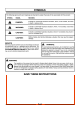
SYMBOLS | Some of the following symbols may be used on this product. Please study them and learn their meaning. Proper interpretation of these symbols will allow you to operate the product better and safer. SYMBOL NAME DESIGNATION/EXPLANATION Volts Voltage Amperes Current Hertz Frequency (cycles per second} Walt Power Hours Time Class il Construction Double-insulated construction Wet Conditions Alert Do not expose to rain or use in damp locations.
SYMBOLS | SYMBOL SIGNAL MEANING The following signal words and meanings are intended to explain the levels of risk associated with this product. A pacer: Indicates an imminently hazardous situation, which, if not avoided, will result in death or serious injury. A warning: Indicates a potentially hazardous situation, which, if not avoided, could result in death or serious injury. A caution: Indicates a potentially hazardous situation, which, if not avoided, may result in minor or moderate injury.
ELECTRICAL DOUBLE INSULATION Double insulation is a concept in safety in electric power tools, which eliminates the need for the usual three wire grounded power cord, All exposed metal parts are isolated from the internal metal motor components with protecting insulation. Double insulated tools do not need to be grounded. A warning: The double insulated system is intended to protect the user from shock resulting from a break in the tool's internal insulation.
FEATURES | PRODUCT SPECIFICATIONS 50118 50120 Input 120, 60 Hz, AC only, 12 Amps Input only, 12 Amps No-load Speed 3,600 r/min. (RPM} No-load Speed. 3,800 r/min. (RPM) Cutting Path .18in. Cutting Path 2000. Height Adjustments. Height Adjustments, -2 into din, Wheel Size. Wheel Size. 7 in. front, 8 in. rear Weight . Weight... 60 Ib. CORD RETAINER GRASS CATCHER (MODEL 50120 ONLY} HEIGHT ADJUSTMENT LEVER MOTOR/BLADE CONTROL ASSEMBLY SIDE DISCHARGE MULCHING PLUG DEFLECTOR (MODEL 50120 ONLY} ir Fig.
FEATURES | KNOW YOUR LAWN MOWER See Figure 2. The safe use of this product requires an understanding of the information on the product and in this operator's manual as well as a knowledge of the project you are attempting. Before use of this product, familiarize yourself with all operating features and safety rules, CORD RETAINER A convenient cord retainer helps Keep the extension cord connection secure during mower operation.
ASSEMBLY | A warning: HANDLE KNOBS _ Never operate the mower without the proper safety a devices in place and working. Never operate the mower with damaged safety devices. Failure to heed this warning can result in serious personal injury. UPPER HANDLE ADJUSTING HANDLE See Figure 3. MW Fully loosen the handle knobs on both sides of the handle. BW Pull up and back on the upper handier to raise the handle inch operating position, Make certain the handles snap into place securely.
ASSEMBLY | INSTALLING THE GRASS CATCHER (MODEL 50120 ONLY) MODEL 50120 ONLY See Figure 6. GRASS CATCHER NOTE: When using the grass catcher, do net install either HANDLE 5 the side discharge deflector or the mulching plug. ; 72 ® Lift the rear discharge door. HOOK! oo ® Lift the grass catcher by its handle and place under the REAR Ge i DISCHARGE rear discharge door so that the hooks on the grass catcher DOOR OPENINGS es are seated on the door rod. ® Release the rear discharge door.
OPERATION | A warning: Do not allow familiarity with this type of product to make you careless. Remember that a careless fraction of a second is sufficient to inflict serious Injury. A warning: Always wear safety goggles or safety glasses with side shields when operating this product. Failure to do so could result in objects being thrown into your eyes, resulting in possible serious injury. A WARNING: Do not use any attachments or accessories not recommended by the manufacturer of this product.
OPERATION | WM For a healthy lawn, always cut off one-third or less of the total length of the grass. HW When cutting heavy grass, reduce walking speed to aglow for more effective cutting and a proper discharge of the clippings. HW Do not cut wet grass. it will stick te the underside of the deck and prevent proper mooching of grass clippings. BW New or thick grass may require a narrower cut.
MAINTENANCE | A warning: When servicing, use only identical replacement parts. Use of any other pairs may create a hazard or cause product damage. A WARNING: Always wear safely goggles or safety glasses with side shields during power toc] operation or when blowing dust, if operation is dusty, also wear a dust mask. GENERAL MAINTENANCE Avoid using solvents when cleaning plastic parts. Most plastics are susceptible to damage from various types of commercial solvents and may be damaged by their use.
MAINTENANCE ® Place the new blade on the shaft against the fan assembly. Make sure it is installed with the curved ends pointing up toward the mower deck and nat down toward the ground, B Replace the blade insulator and spacer, then thread the bide nut on the shaft and finger tighten. NOTE: Marks certain all parts are replaced in the exact order in which they were removed. ® Torque the blade nut down using a torque wrench {not provided) to ensure the bolt is properly tightened.
MAINTENANCE | REPLACING WHEELS See Figure 16. To replace a wheel: MW Disconnect the mower from the power supply. W Turn the mower on its side. HW Using a flat blade screwdriver, pry off the hubcap. WM Remove the cotter pin from the wheel axle, then remove the wheel. MW Replace with new wheel and insert new cotter pin to secure. HW Replace hubcap. STORING THE MOWER See Figure 17. M Disconnect the mower from the power supply.
TROUBLESHOOTING | ( Problem Possible Cause Solution ) Handle not in position. Carriage bolts not seated properly. Handle knobs not tightened. Adjust the height of the handle and make sure the carriage bolts are seated properly. Tighten handle knobs. Mower rot starting. Extension cord not connected to the mower plug. Extension cord not connected to power source. Tripped circuit breaker in the house. Motor control switch defective.
EXPLODED VIEW/PARTS LIST | MODEL 50120 Key Key No. Part No. Description Qty. No. Part No. Description Qty.
WARRANTY | 7 “\ LIMITED WARRANTY FOR CORDED ELECTRIC MODELS. This product is manufactured for the American Lawn Mower Company/Great States Corporation.
ELECTRIC LAWN MOWER United States Patent Pending 18 in. 50118 20 in. 50120 SERVICE For parts or service, contact your nearest Earth Wise authorized service dealer. Be sure to provide all relevant information when you call or visit. For the location of the authorized service dealer nearest you, please call 1-800-377-5888 In Canada call 1-800-561-0004 or visit us online at REPAIR PARTS The model number of this tool is found on a plate or label attached to the housing.