
Specifications


166119 8/31/2006
6
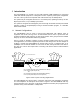
2.1 Multiplexer Operation
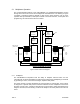
The central hardware element of the Nx8-DualMUX is a multiplexer/demultiplexer function
through which all end-to-end user and management information flows. The drawing of Figure
3 provides a high-level reference diagram for this function. Other functions such as clock
synthesis and synchronization, backup and restoral of channels and links, control paths and
programming, and user interfaces are not included.
Composite Port I/F
Multiplexer
.
.
Input
FIFOs
x16
.
.
Port Loop
Functions
Demultiplexer
.
.
Output
FIFOs
x16
.
.
Port Loop
Functions
Port Loops
Port
RxD
x16
Port
TxD
x16
Allocation
Memory
Frame
Generation
& Counter
Allocation
Memory
Frame
Synch.
Detect
& Counter
Mgt Link TxD
(from Proc)
Mgt Link RxD
(to Proc)
Loopback
Functions
MUX BLOCK DIAGRAM - DATA FLOW
Sync
Figure 3 MUX Data Flow Diagram
2.1.1 Multiplexer
The Nx8-DualMUX incorporates both the ability to multiplex outbound data over the
composite link as well as demultiplex the same inbound data stream. Multiplexing is achieved
by generating a “frame”, which is a fixed-length, repetitive data pattern.
The frame consists of a frame bit followed by a fixed number of “timeslot” bits, each of which
is assigned to a specific data port that has been allocated. As the multiplexer scans across
the frame a bit at a time, it inserts a serial bit from the port buffer to which that timeslot bit is
assigned. Therefore, the bits forming a channel are always in the same position from frame to
frame.