
Specifications
166119 8/31/2006
9
minimizes the duration of the interruption and eliminates the need for the operator to
manually enter the sequence of commands.
The Nx8-DualMUX has an additional feature that re-allocates channels to new timeslots
when the composite link rate is changed by the user. This is particularly important when the
composite link rate is decreased, with a corresponding reduction in the size of the timeslot
allocation memory. Without re-allocating the port channels to fit in the smaller allocation
memory, many of the channels would lose the ability to pass end-to-end data.
2.1.4.1 Non-disruption of Channels
The process of configuration of any one channel is non-disruptive to the flow of data among
other active (allocated) channels. Thus any channel may be allocated, de-allocated, or
modified in any of it‟s parameters, without risk of disrupting data among those ports which are
in use and do not require reconfiguration.
2.1.4.2 Total Bandwidth Availability
Channels are allocated by their required bandwidth, and the total composite bandwidth
needed to support all active channels is simply the sum of the channel bandwidth
requirement, plus the fixed overhead of 8000bps for framing and the management channel.
When a channel is de-allocated it makes available that same bandwidth, added to any
available pre-existing bandwidth, to be used by other channels at a later reconfiguration
point.
2.1.5 Management Channel
The Nx8-DualMUX reserves a fixed sub-channel of 1200 bps for end-to-end, embedded
communication between a pair of linked systems. Once both units have become
synchronized, this channel is used for system management functions. These functions
include remote user configuration, message and command acknowledgments, status
reporting, program downloading, and test/maintenance commands.
2.1.6 Composite Port Operation
The composite port carries all end-to-end information between the systems comprising a
linked pair of multiplexes. As a DTE interface, a data clock signal(s) at the port is a required
input from an attached DCE device. The clock rate must be one of several selectable
multiples of 8kHz (see Table 1). Additionally, the Nx8-DualMUX composite port must be
configured to that same rate in order for the internal port clock generators to work properly.
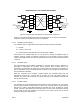
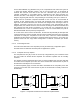
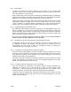
2.1.6.1 Internal Source Clock Timing
It is possible to use the Nx8-DualMUX as a source of timing on one end of a link. This
requires a special cable arrangement as shown in Figure 5 and performing the required
configuration steps to program the composite port. In this example, multiplexer 1, on the left,
generates a clock signal on TXCE based on the internal crystal oscillator. This clock is used
to clock out TxD. On the opposite side, the transmit clock and data signals are crossed over
to the receive side and the clock is used to latch RxD. As received, the RxC signal on
multiplexer 2 is looped back to the clock source block, and used as the outgoing TXCE. The
transmit clock and data signals are crossed over again in the same manner as RxC and RxD,
respectively. Thus all clocks are derived from a single source.