
Specifications

166119 8/31/2006
10
RXD
RXC
TXD
TXC
TXCE
RXD
RXC
TXD
TXC
TXCE
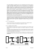
Loop-timed
DTE
Internal-timed
DTE
Tx data
latch
Transmitted
TXCE is used to
clock out TXD
Cross-over "null modem"
cable connections
Rx data
latch
Rx data
latch
Tx data
latch
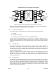
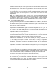
COMPOSITE DTE to DTE CONNECTION DIAGRAM
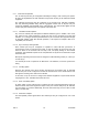
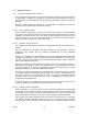
Internal
Oscillator
Clock
Source
RxC
Loop
Clock
Source
Transmitted
TxCE is used to
clock out TXD
Multiplexer 1 Multiplexer 2
TxCE Enable
TxCE Enable
Figure 5 Composite port cable diagram for DTE-to-DTE connections
Other non-symmetrical arrangements based on this approach to connect with transmission
equipment requiring an external timing source are possible.
2.1.6.2 Hardware Interface Options
The composite port is configurable for three different electrical interface standards:
1) RS-232
2) V.35 (V.11 and V.24)
3) EIA-530 (also includes RS-449 and X.21 with cable adapter)
These options are programmable and do not require the setting of hardware straps or
switches. However, support for standard connectors for V.35, RS-449, and X.21 requires
cables, which adapt between the native composite DB-25 connector and the desired interface
connector.
2.1.6.3 Link State Option
The composite link may be enabled or disabled by command. When the link is disabled, no
information is transmitted, and received data is ignored. Since received data is not
recognized, synchronization as reflected in the SYNC status is reset and synchronization is
lost. No information can be exchanged between systems via the management channel when
the composite link is disabled.
When the composite link is enabled, complete frames are transmitted along with the
management channel. The received data is accepted, and if a valid framing pattern is
detected, the system will synchronize and begin receiving the management channel data
from the remote system.
2.1.6.4 Link Rate Option
The operator may modify the expected received clock rate of the composite port. This may be
done on either the local or remote system. In either case, a system that is in synchronization
will lose sync until the actual DCE matches the selected rate. Once completed on remote
system, a change in the selected clock rate will result in the loss of the management channel
and the ability to send any subsequent commands to the remote system until the remote
DCE clock matches the selected rate.