
Specifications

166119 8/31/2006
13
In the first and default mode, the DCD signal follows the state of the composite
synchronization detector. Thus if SYNC is ON, DCD at the channel port is ON, and OFF if
SYNC is OFF.
In the second mode, the DCD signal may be configured to respond according to the state of
the corresponding channel port RTS input at the far end of the link. This configuration option
may be set at either end, or both ends of the channel as needed. If the option is set at one
end of the channel, the other may be freely set to one of the other two modes.
2.1.7.6 Channel Port Loop Options
Each channel port may be selectively put into three loop mode configurations. The two loop
modes are termed Local Loopback and Remote Loopback and may be used singly, or in
combination.
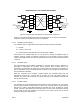
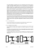
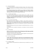
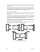
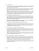
The diagrams of Figure 7 illustrate the data paths followed for each of the three combinations
of loop modes. In local loopback (top, left), the data that is received at the channel port TxD
lead is sent to the RxD lead of the interface in place of the data that is normally sent, while a
constant “Mark” signal is sent to the transmit side of the channel.
In remote loopback (top, right), the data that is received from the channel is sent back to the
transmit side of the channel in place of data that is normally input from the port TxD lead,
while a constant “Mark” signal is sent to the RxD lead.
When both local and remote loopback are invoked, the two loop functions are overlaid with
the resulting loop paths as shown in the bottom diagram of Figure 7.
TXD
RXD
Channel
Port N
Nx64-MUX
(Channel N)
RxD
'MARK'
Local Loopback
(Channel N)
TxD
TXD
RXD
Channel
Port N
Nx64-MUX
(Channel N)
RxD
Local & Remote Loopback
Channel
Port N
TXD
RXD
Nx64-MUX
(Channel N)
RxD
'MARK'
Remote Loopback
(Channel N)
TxD
(Channel N)
TxD
Figure 7 Three Channel Port Loopback Modes