
Specifications

166119 8/31/2006
18
2.2.9 Node ID Information
A unique node name, of up to 20 alphanumeric ASCII characters, may be entered into the
non-volatile memory of each system in order to identify that system in the customer‟s
network.
The node id is displayed on the second line of every menu screen.
2.2.10 Log-In, Log-Off and Change Password
When the system is powered-on, or after a reset command, the operator must login in order
to access the management system. Once logged in, the operator may change the password
at any time via the Change Password command on the Log In Menu.
The system is initially programmed with the password “default” when shipped from the
factory. This permits the operator the means to initially login and establish a personal
password.
If the password is lost, the customer should contact East Coast Datacom, Inc. for instructions
on how to gain access to the Change Password screen entry function.
2.3 Backup, Restoral, and Bandwidth Assignment Operations
The Nx8-DualMUX allows for the distribution of channel bandwidth over two aggregate links,
and for the restoral of specific channels to an operational link under single-link failure
conditions. The flexibility of bandwidth distribution and fault-tolerance offers many options to
configuring a system. This section will address this facet of operation and some of the
possible configuration scenarios.
2.3.1 Channel Failover Modes and Associated Parameters
Before considering system configurations, it is important to understand channel failover mode
assignments. Channel failover modes determine under what conditions a channel is switched
to the alternate composite link from it‟s home composite link (the one to which it is originally
assigned). Priorities also determine if a channel circuit is to be bumped for a higher priority
channel. Other parameters associated with the channel affect the backup clock rate and
restoral time.
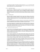
2.3.1.1 Failover Modes
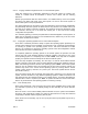
There are two priority attributes, each with two possible values. These can best be
represented in the following matrix and together define the failover modes:
Table 2
CAN BE
BUMPED
CANNOT BE
BUMPED
CAN BE
BUMPED
CANNOT BE
BUMPED
SEEKS BACKUP
NO BACKUP
(FIXED)
HIGH
LOW
PRIORITY MATRIX (FAILOVER MODES)