
Specifications


166119 8/31/2006
35
4 User Interface
4.1 Indicators
4.1.1 Processor Card
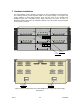
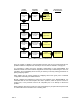
The Processor card has fourteen LED indicators on its front panel as shown in Figure 13.
Each indicator‟s definition is as follows:
POWER (Green) – When ON indicates that the power supply is providing regulated DC
power to the system. IMPORTANT NOTE: If this indicator is OFF, the operator
should check before assuming that AC Mains power is not applied to the system.
SYS (Bi-color; Yellow and Green) – General system status. When Green, indicates the
system is functioning in the absence of detected faults. When Yellow, indicates
that the system has detected an operational fault, or, is in the process of
determining system status following a power-on cycle or system reset. When
OFF, the system is either in a continuous reset state, or has failed and is non-
functional.
SYNC (Bi-color; Yellow and Green) – When ON indicates that the received link framing
signal has been correctly detected on the corresponding composite port and the
local unit is in synchronization with the remote unit. (The upper LED is for
composite port A and the lower for composite port B.)
TXC (Bi-color; Yellow and Green) – When Green indicates the presence of transmit data
clock on the corresponding Composite port interface. If this indicator is Yellow,
then the clock is not present. (The upper LED is for composite port A and the
lower for composite port B.)
RXC (Bi-color; Yellow and Green) – When Green indicates the presence of receive data
clock on the corresponding Composite port interface. If this indicator is Yellow,
then the clock is not present. (The upper LED is for composite port A and the
lower for composite port B.)
RX D (Green) – When ON indicates the presence of signal activity on the corresponding
Composite port interface receive data lead. A constant mark or space condition
on the data lead will result in the indicator turning OFF. (The upper LED is for
composite port A and the lower for composite port B.)
TX D (Green) – When ON indicates the presence of signal activity on the corresponding
Composite port interface transmit data lead. A constant mark or space condition
on the data lead will result in the indicator turning OFF. (The upper LED is for
composite port A and the lower for composite port B.)
COMP LOOP (Yellow) – When ON indicates that the corresponding composite port is
either in the Transmit or Receive Loopback Mode. When Flashing (~ 1 sec.)
indicates that the corresponding remote composite port is in either Transmit or
Receive Loopback Mode. (The upper LED is for composite port A and the lower
for composite port B.)