
Specifications


166119 8/31/2006
36
POWER
SYS STATUS
SYNC
PT# 166102
MODEL: PROCESSOR, Nx-MUX
Nx-MUX
DISCONNECT AC POWER SOURCE
BEFORE REMOVING THIS MODULE
NOTICE:
TXC
RXC
RXD
TXD
LOOP
A
COMPOSITE
B
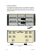
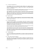
Figure 13 Processor Card Front Panel
4.1.2 Port I/O Card
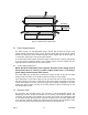
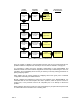
The Processor card has eight LED indicators on it‟s front panel as shown in Figure 14,
arranged in four groups of two LED‟s each. The meaning of each pair of indicators is the
same, although each pair applies to a different port. Each pair of indicator‟s definition is as
follows:
CH +n ACTIVE (Green) – When ON indicates that the corresponding port is allocated
end-to-end channel space, or bandwidth, by the multiplexer. When Flashing (~ 1
sec.) indicates the same as ON except that SYNC is not valid and therefore
inbound data cannot be demultiplexed. In this case the channel received data at
the port and the transmitted data to the multiplexer is substituted with a MARK
condition.
CH +n LOOP (Yellow) – When ON indicates that the corresponding local channel port is
in one or both of the Local or Remote channel loopback modes. When Flashing
(~ 1 sec.) indicates that the corresponding remote channel port is in one or both
of the Local or Remote channel loopback modes
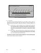
The notation of “+n” refers to the index number associated with each pair of indicators. These
numbers may be added to the Port I/O card group number (i.e., 0, 4, 8, and 12) to determine
the port number to which the indicator corresponds.