
Specifications

166119 8/31/2006
37
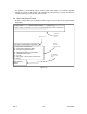
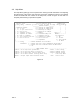
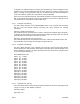
CH +1 ACTIVE
CH +1 LOOP
CH +2 ACTIVE
CH +3 ACTIVE
CH +4 ACTIVE
CH +2 LOOP
CH +3 LOOP
CH +4 LOOP
PT# 166007
MODEL: 4-PORT I/O
Figure 14 Port I/O Card Front Panel
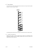
4.1.3 Redundant Power Supply
In systems configured with redundant power supplies, the front panel of each supply has a
single two-color (green/yellow) LED that indicates the operational state of the associated DC
power supply.
When the indicator is Green, the power supply is functioning normally and is capable of
powering the system alone should the alternate supply fail. When the indicator is Yellow, the
power supply has either failed or has lost the ability to provide sufficient DC power.
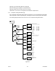
4.2 Console Operation
Managing the operation, configuration and status of the Nx8-DualMUX requires the
connection of a terminal via the Console Port. Through the terminal interface, the user is
presented a series of hierarchical menus through which options are selected.
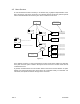
The hierarchical menu structure is depicted in Error! Reference source not found.. Menu
choices are either additional menus providing a further detail of user choices, or are
parameter options. The diagram displays menus that lead to further menus as rectangles with
pointed bottoms, whereas menus allowing parameter selection are rectangles with the
parameter options listed directly beneath the rectangle.
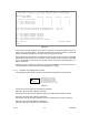
4.2.1 Console Setup
The Console Port of the Nx8-DualMUX has hardware interface characteristics as shown in
the following table, which may be noted when configuring a terminal emulation program such
as HyperTerminal:
Elec. Interface
RS-232, DCE
Timing
9600 Baud
Connector
DB-25, Female
Format
Async, 8bit data, No parity, 1Stop bit
Flow Control
None