Kit Packing C5 Vette PAC controller ____ Pump w/4 Feet shielded cable ____ 4 Feet 7/16 split loom ____ 2 long wire ties ____ PAC wiring + DS tape ____ 18 inch hose –6 -6 ____ 22 inch hose –4 –4 ____ 32 inch hose -4 –4 ____ Methanol Filter ____ 90’ 3/8 –6 fitting ____ 90’ 3/8 –4 fitting ____ MAP Sensor w/regulator ____ Brass T for MAP ____ 4 self tapping w/washers ____ Cap w/vent ____ Tank Plug ____ Bulkhead w/seal ____ 90’ ¼-6 fitting ____ Nozzle w/washers + adapter ____ Low level grommet ____ Check valve _
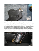
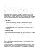
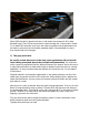
Alky Pump install Important notes… Do Not Mount pump with head facing upwards as this will allow water to collect inside sleeve and ruin motor. Please install as pictured, It can also be installed horizontally as long as the pitch does not allow water to collect in sleeve. Any question..
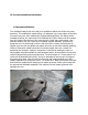
C5 Corvette installation instructions 1) The tank modification The windshield washer tank will need to be modified to deliver the fluid to the pump assembly. The modification entails drilling a ¾ diameter hole in the bottom of the tank, its lowest rear point, then installing the supplied bulkhead fitting.
2) Pump mounting Before mounting the pump, install the brass 90 degree fitting on the inlet of the pump, use the larger of the two fittings provided. The top of the pump will be marked with an arrow indicating flow direction. Next install the smaller 90 degree brass fitting on the outlet of the pump. Careful when tightening these fittings as the housing on the pump can break. Rule of thumb, tighten by hand then one full turn.
3) Nozzle The nozzle will be placed before throttle body. Install head of nozzle in the upper portion of the air bridge 2 o’clock position on Mag cars or in the upper portion of the pipe on supercharged applications. The installed height of the nozzle must be higher than the tank. Else siphoning can occur. Simply drill 3/8 diameter hole into location, feed nozzle in leaving one sealing washer on the inside..
the MAP sensor. At this point remove the lower panel under the dash, and the panel that goes under the steering column. Drill holes and run LED wiring from the pillar to underneath the dash. The turn-on LED has a orange/brown wire. Next is locate a solid ground point under the dash. The black wire from the PAC power distribution box will be attached to this, and the black wire from the 5 volt MAP regulator(if supplied with system).
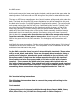
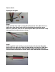
2)Razor blade 3)Heat gun or lighter Step 1 Strip insulation from end of pump cable and separate wires. Note there are three wires. Red, Black, bare wire. Strip insulation Red and black wires. About ¼ inch is fine. And use the small supplied Male spade terminals. Crimp the terminals from the bottom as shown. Step 2 Slide large black heat-shrink over terminals and cable. Next is slide white heat-shrink over Bare wire, slide Red heat-shrink over Red wire. Slide Black heat-shrink over Black wire.
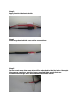
Step 3 Apply heat to the heat-shrink. Step4 Slide large heat-shrink over entire connections Step 5 In the event more than one wire will be attached to the Red wire. Example Map sensor regulator, use the larger supplied Male spade that can accommodate larger wire and assemble as stated above.
Mount PAC controller in aluminum frame, it will need to be loosened to fit in place. Reinstall frame. Then ZIP tie the controller in place through the 2 lower holes in frame. Try to install PAC controller as far up in the frame as possible so that adjustments can be made by removing the trunk button assembly quickly. Once adjusted on a dyno, they should need to be changed. 7) The gray/violet wire Be careful on how this wire is to be used, most applications will not benefit from it being connected.
8) Final At this point you’ve concluded the installation, first thing to do is before putting alcohol/water into the tank, is turn the ignition “on” and set the blue gain knob to the middle position. Next depress the black test button and observe the turn-on LED next to the boost gauge light up. At this point observe the low washer fluid lamp, which should also be lit since the tank is empty.
Individual results may vary, enjoy the product. 10) Interference On some types of scan-tools it may be possible the PWM signal to drive the pump can give erroneous readings. The simple fix is to run the power to the PAC red wire from a relay switched battery source. The following is an overview how this is accomplished only if needed. A wire of suitable gauge 10-12, is run from battery “+” terminal to the inside of the vehicle. A 20 amp fuse is recommended at the battery connection.
PAC- Progressive Alcohol Controller Introduction The PAC is a versatile electronic motor controller using pulse width modulation technology. It allows the user to custom tailor voltage output to the injection pump being used so that it increases pressure with the increase in voltage output coming from the vehicle MAP sensor. Recommended that vehicle have a 3 bar map sensor for better voltage control. Will support any injection pump rated up to 15 amps.
can be routed from a relay activated by the ignition switch. Black goes to chassis ground. The connections to the injection pump are the Red/Black/White wires coming from the main controller. Connections to these using the supplied spade connectors. Red wire to from the pump to Red wire from main controller. Black wire from pump to Black wire from main controller. There is a “drain/silver/bare” wire for the pressure sensing, this will be connected to the White terminal.
pump as the signal from the MAP sensor increases. Turning this knob clockwise will increase output voltage multiplication and slightly increase the initial pump speed. Only way to know what is best suited for your particular application is trial and error. Tuning suggestions First, best place to tune an alcohol system is the race track under closed track conditions. I do not recommend hi-speed testing of products on public roadways where you or others may be indanger.
setting in main controller. Once this is done, monitoring engine knock, race car…. If knock retard is encountered, ascertain if the knock is occurring as the boost increases(transitional) or is occurring at due to high boost levels. Adding gain to the knob(clockwise) increases pump pressure output. If the knock is occurring due to transitional, increasing initial pump speed or decreasing turn-on point will aid these conditions.