C6 Corvette Supercharger Kit Instructions
ECS SC 600 Instructions (C6) These instructions are meant to serve as a guide to the installation of the ECS SC600 Supercharging kit. Please be sure to use all safety equipment including gloves, and eye protection. Please use proper techniques to capture and dispose of, or reuse factory fluids. Utilization of the proper tools will make the install smoother and faster.
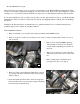
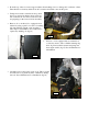
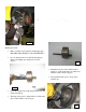
a • Unclip coolant line from top radiator shroud, and remove upper radiator shroud by removing 4 retaining bolts (10mm) (fig. 3a & b) Upper shroud will not be reused. • Raise car, remove wheels from car. • From below, we will be removing the hardware holding the front fascia to the radiator support and intake air shroud. The front fascia will NOT be removed.
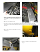
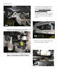
• Remove center section of front air dam by removing 310mm screws in front of air damn, (pic) and 2 - 7mm underneath fascia. Remove front air dam from car. (fig. 6) 7 6 • • Remove passenger side brake duct housing by removing the two retaining clips. Outermost 7mm screw, and 3rd screw from side of car. (Fig. 7) We are now removing the intake shroud and horns inside the nose. Using a fork tool, remove 8 black retaining clips (on sides) (fig. 8), and 4 - 7mm screws on lower front air shroud. (fig. 9).
• Moving under the passenger side, remove the horn assembly with a 13mm socket (fig.10) 10 Behind the horns, and attached to the intake shroud is the outside air temperature sensor. Unclip and free sensor from passenger side of front air shroud. (fig. 11) • 11 • Use fork tool to unclip two black retaining clips from main upper air shroud. (fig 12) 12 13 • Remove front sway bar from car by removing the 2 -18mm nuts on lower control arms, and 4- 13mm bolts from engine cradle.
• From the top of the car, remove upper radiator shroud taking car not to damage AC condenser or lines. Take the time to clean any debris from AC condenser and radiator area at this point. • Unclip front 1 inch coolant line from top front shroud, as well as fan harness from passenger side of shroud. Do not remove from car as we are preparing for the removal of fan assembly.
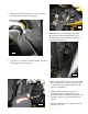
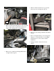
Pinning the Crank • Loosen the 4 nuts supporting the front engine cradle assembly with a 21mm socket. DO NOT REMOVE NUTS FROM SUPPORT BOLTS. The goal is to drop the front cradle assembly approximately 3/4 of an inch to prepare for removal of the rack. Use a chisel or socket to space down cradle as shown. (fig 17) 17 • Remove two bolts that hold the power steering cooler to engine cradle with a 10mm socket. (fig. 18) 18 • Remove tie rod ends (18mm socket) and remove from spindles.
• With an 18mm wrench remove top pressure line from power steering rack. (fig. 21) 21 • Remove 10mm bolt holding drivers side front brake line to engine cradle. (fig 22) Free bracket from cradle. Save all hardware for reinstallation. 22 • Remove power steering return line with 18mm wrench. • Remove clamp that holds power steering lines (fig 23) to cooler and remove cooler. Retain return line from cooler to rack for future installation. • Unplug electrical connector from rack.
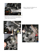
• Remove 2 18mm bolts holding the power steering rack in place. (fig 25) 25 • If all clips removed, as out previously described, you Push brakeare lines back and of the way, If all clips are removed, described, you should be ableastopreviously clear the rack snout of theshould lines. be able to rack clearand the remove rack snout of theframe lines. and Rotate rack Rotate between engine and remove between frame below. and engine cradle as cradle as shown in pictures shown.
is out of the car and arethe ready to pin theare crank now. • Rack Congratulations. Rack is you out of car and you ready to pin the crank. Stop have a beer. (not supplied with kit) 26e Pinning the Crank • Remove 24mm stock crank bolt with impact gun.
• Remove crank fixture • Lightly Lightlyblow blowout outcrank crankthreads threadsand andpin pinhole holetotoremove remove metal shavings (BE SURE TO any metalany shavings or chips. or (BEchips. SURE THE ENGINE AND THROTTLESAFTY BODY GLASSES) ARE CAPPED OFF AND BE WEARING THAT YOU ARE WEARING SAFETY GLASSES.) • • With a punch and hammer, tap the crank pin into Insert hole. supplied pin in the new hole. Insert new Crank Bolt (supplied in kit) and tighten to 235ft/lbs.
Install supplied 3/8” thick washer on the AC tensioner pulley bolt as shown in picture to the left. With AC belt still in place, install the preassembled AC tensioner and the main tensioner bracket at the same time using the new supplied 8mm bolt to tighten the AC tensioner in place. (fig. 33) • With belt in place, install pre assembled ac tensioner (fig 33) as shown and tighten. • Use a 15mm socket to unload tensioner and replace AC belt.
A B Using the supplied relocation bracket in picture A and one of the 7mm fascia speed nuts and bolts, you will need to relocate the transmission cooler lines away from the motor. Use one of the oil pan bolts, as in picture B, and relocate the transmission line bracket away from the engine oil pan, as in picture C. Next, install the supplied heavy duty tensioner and pulley assembly using the supplied 9/16 bolt on to the previously installed bracket, as shown in picture D.
• Remove the 4 – 13mm bolts holding in the radiator support cradle to frame. Do not remove frame from car, just drop aprox 1-2 inches to allow for installation of radiator relocation bars included in kit.(fig 36). 36 • Install the (2) radiator cradle relocation bars with the 4 factory 13mm bolts that held the cradle in place. Bolt Radiator support cradle to relocation bars with the 4 supplied 8 mm x 25mm bolts with flat and lock washers in place.
• Place lower radiator hose on workbench, and cut hose in middle as shown. Install supplied worm clamps and insert the supplied radiator hose extension pipe into hose as shown. Tighten top worm clamp, leaving lower portion loose until reinstallation in car. (fig 40) 40 • Set radiator and AC condenser into lower radiator support mounts, and reinstall lower radiator hose. Be sure to tighten lower worm clamp and re spring clamps at this point.
• Install bracket with supplied ¼ in bolts and washers. (fig 44) 44 From left edge of installed bracket measure 13 inches to right and mark support with a line to guide installation of right side intercooler support bracket. Place the intercooler support bracket against line as shown, mark holes and drill frame (with the supplied Q bit), to accept rivet nuts. Insert rivet nuts into holes and set in place following the same procedure as left side support.
48 Relocate the outside air temperature sensor from your previous removed radiator shroud. Reattach to plastic air • Strap the outside temperature sensorcradle from as dam shroud located right inairfront of the radiator your previously removed radiator shroud. shown in picture 48. Reattach utilizing provided zip tie to forward, passenger side leg of the radiator support cradle as pictured. (fig 48) 48 • On the lower, passenger side of the radiator support cradle, locate horn wires and plug.
• Install 3 in. rubber coupler onto intercooler Do notDo not using supplied 3 in clamps. worm clamps. tighten worm clamps as of yet. We will be fitting the charge tubes and will need to adjust fitment as we go along. • Next, slide 3 in aluminum “U tube” to coupler through end of radiator cradle and attach with supplied ¼ x 1 in bolt to mounting point on back side of radiator cradle as pictured. (fig 52). 52 • Next, take your fan assembly and notch the upper most right hand corner.
Z06 and Z51 Oil Cooler Relocation Brackets If your car comes equipped with a Z06 or Z51 oil cooler, you will need to use the supplied brackets and hardware to relocate the cooler from the factory location. Refer the the pictures on this page to install the ECS supplied relocation brackets using the driver’s side and passenger side front sway bar mount 13mm bolt.
• To allow for clearance of the air intake and charge tube, gently take a hammer or mallet and tap down the top rails of the radiator as shown. On the passenger side you will find a split in the top rail that measures aprox. 4 ¾ inches from the right tank, and in the center, between the intercooler and throttle body will need to be clearance. (fig 55a, b) 55a 55b • 56 Install drivers side upper radiator support bracket with stock 10 mm bolts from previously removed radiator support.
• From shipped head unit assembly, remove cylinder head mounting bracket (with engraved ECS) from assembly. Place your 2 -15mm belt tensioner bolts through front of mounting plate with the 2 supplied .070 water pump spacers as shown, leaving the two 17mm bolts with polished aluminum spacers, as well as the two 14mm bolts and washers in place (see fig 57). Take your time with this step.
• Install supplied 3 in rubber 90 degree hose to head unit with a 5-10 offset towards front of car as shown. (fig 61) Be certain to tighten worm clamp. 61 • Slide head unit and 90 degree hose into car as shown. Sliding hose between passenger side fender and 1 in cooling hose. Guide rubber hose in front of steering rack and engine cradle. Be sure to slide worm clamp over charge tube prior to connecting.
• Install 2nd head unit spacer on the previously installed lower passenger side 3/8ths bolt as shown. (fig 63) • Install the two remaining 3/8ths studs and head unit spacers to head unit and mounting bracket with supplied washers and lock nuts as shown. (fig 64) 63 • Tighten ALL Head unit/bracket hardware. • On top of head unit, remove top plug and install the head unit vent with a 3/16ths allen wrench.
Belt Installation • Install supplied belt, starting at the head unit, and pulleys as shown idler in theall diagram Loosenthrough the head unit adjustable the waybelow. by (create) To adjust lower tensioner, place arm lock pliers loosening the two 9/16” lock nuts on the swing on lower tab of tensioner and pull with socket and (fig. 67b). extension or pipe for additional leverage.
lower tensioner between the 12 and 1 o’clock position. (fig 67a,b) The tensioner should be at the 1 o’clock position once the belt is tightened to achieve the best possible belt tension. 66 67a 67b Attach lower rubber 90 degree charge tube to aluminum U-tube, being certain to tighten all clamps Onceon allcharge of the tensioner tubes. bolts are tight, install the 90 degree discharge tube coming off of the supercharger.
• Use supplied zip tie to attach drain line to power steering rack to ensure easy access for future head oil changes. (fig 69) 69 • Remove lower rubber power steering line, and re attach to upper rubber power steering line with supplied 3/8ths worm clamp. Re adjust any hard lines and line protectors as necessary to prevent any chafing. (fig 70) Install 2 fascia extension tabs into existing tabs on radiator support as shown.
• Remove two screw tabs from previously removed lower front air shroud as shown (fig 72), and install on leading edge of front inner fender liners.(fig 73) Secure drivers side with factory 7mm bolt. 72 • Trim passenger side inner fender well clear charge tube. Reinstall factory brake duct and brake duct housing during reinstallation; securing with factory 7mm bolts. (fig 74) 73 • Measure overhang of front facia to radiator support cross bar.
• • Take front air dam and lay a straight edge across, from mounting tab to mounting tab. Score with a razor knife until through plastic. Remove and discard excess material and mounting tabs. (fig 76) Slide air dam between fascia and radiator support and attach to radiator cradle with factory 10mm bolts and plastic push in retaining clips. Attach front fascia to fascia extension tabs with factory 7mm bolts.
Restrictor Plate Installation Your ECS kit is supplied with an air flow restrictor plate to regulate overall boost. This restrictor plate is strongly recommended on most stock applications. Place restrictor plate inside of air filter, as pictured above, and let it rest inside the built-in groove of the air filter. Next, attach the plastic inlet tube to the air filter and restrictor assembly, as shown below.
• At this point go back under the car, and tighten the t-bolt worm clamps on the 3 inch rubber coupler that attaches the intercooler to the U tube. (fig 80) 81 80 • • Install inlet duct, filter end first then pulling back and attaching directly to blower with 10mm worm clamp. (fig 82) • Remove vacuum hose from brake booster, cutting at shown. (figs 83, 84) Install supplied vacuum T fitting tightening with supplied ½ in worm clamps.
• 85a To install catch can assembly: Cut 2 – 2 ½ in pieces of supplied 3/8 fuel line and attach to either side of supplied PVC valve. Note directional arrow on PVC valve. Screw 3/8th barbed fittings into catch can with 9/16ths wrench. Attach PVC hose to barbed fitting on catch can again noting directional arrows on both PVC and catch can. Attach remainder of supplied 3/8th inch hose to opposite side of catch can. During installation, both arrows will be installed towards intake manifold vacuum port.
• Attach 3/8ths rubber hose from air cleaner, to the vent port on passenger side valve cover. Move EVAP solenoid back to factory location and reattach wiring harness to solenoid. (fig 87) • Carefully remove factory spark plug wires and remove factory spark plugs. Install supplied NGK TR-6 spark plugs, and verify gap is .038 on each. Install plugs, and reattach factory spark plug wires. If replacement plugs are ever necessary use only NGK TR-6’s.
• With fuel line removal tool, remove braided fuel line on drivers side fuel rail. • Remove fuel rail from intake manifold, pulling injectors from manifold. (fig 90) • Using a screwdriver, slide injector retaining clips off injectors and remove stock injectors from rail. Using a small screwdriver or pick tool, carefully remove bottom o-rings from supplied Motron 60’s, and replace with supplied (brown) o-rings. (This is necessary with all Motron injector applications).
ECS Fuel Pump Booster Instructions C6 Locate wiring harness going to fuse box. It should have blue tape wrapped around the plastic loom, find the heavy GRAY wire on either side of the connector. Cut the heavy GRAY wire on either side of the connector leaving enough room to strip the wire for the new connector.
Next using the supplied hardware ground the BLACK wire from the ECS bap to the existing stud on the frame Find a suitable location for the supplied Hobbs switch near a vaccum source and install the supplied vacuum tee and run supplied 5/32 vacuum hose from the installed vacuum tee to the barb fitting on the hobbs switch. The remaining brown wire from ECS bap goes to one of the hobbs switch terminals, it does NOT matter which one for polarity is not important.
Run 5/32nd hose (provided) from vacuum barb fitting on MSD unit to barbed fitting on the previously installed vacuum t fitting (in brake booster vacuum hose). • Recover wiring harness with factory loom, and cover with electrical tape as necessary. • Reinstall fuse panel cover • Reinstall battery and battery hold down. • Install front black shield with supplied dzus fasteners. (fig 104) Install supplied breather cap on oil filler neck Reinstall front tires. Reinstall Fuel rail covers.
Important Information Urgent Reading SALES m COMPLETE SERVICES m PARTS m PHONE: 609-752-0321 m FAX: 609-752-0320 Paxton 1500SL / 2200SL Maintenance Schedule Check the fluid level using the dipstick periodically. Initial supercharger fluid change must be performed at 2,500 miles. The supercharger fluid must be changed every 3,500 miles maximum thereafter. Drain the fluid and refill the unit with approximately 4 o.z.