Kodak DryView 8150 Laser Imager User Guide
Eastman Kodak Company 343 State Street Rochester, NY 14650 © Eastman Kodak Company, 2004 Kodak and DryView are trademarks of Eastman Kodak Company. 7F3319 Catalog number 1779545 Rev.
Warranty and Limitation of Liability Important Notice to Purchaser: Kodak warrants that Kodak hardware products will be free from defects in parts, materials and manufacture for a period of one (1) year from date of installation. For defects occurring during the warranty period and about which Kodak has received notice during the warranty period, Kodak will provide Customer with free replacement parts and labor to replace warranty-covered items.
software attacks, and additional professional services to assist customers to eliminate attack consequences and/or harden their information technology infrastructure against future attacks, is billable unless a clear and specific contractual agreement states otherwise. End User License Agreement (EULA) EASTMAN KODAK COMPANY Health Imaging Software End User License Agreement Read the following terms and conditions carefully before using this Software.
Customer for the purposes stated above, the Customer must affix the same copyright or other proprietary rights notice as was originally affixed to the Software when delivered by Kodak. Customer may not otherwise reverse engineer, decompile, or otherwise derive the source code for the Software program. Copyright. The Software is owned by Kodak or its suppliers and protected by copyright laws and international treaties. You may not copy the Software other than as expressly provided in this license.
operation of any of the Software will be uninterrupted or error free, or (ii) functions contained in the Software will operate in the combinations which may be selected for use by, or meet Customer's requirements. This warranty will be void if the Software is modified without the written consent of Kodak.
State Street, Rochester, New York, 14650. END-USER LICENSE AGREEMENT FOR MICROSOFT DESKTOP OPERATING SYSTEMS IMPORTANT-READ CAREFULLY: THIS END-USER LICENSE AGREEMENT ("EULA") IS A LEGAL AGREEMENT BETWEEN YOU (EITHER AN INDIVIDUAL OR A SINGLE ENTITY) AND THE MANUFACTURER ("MANUFACTURER") OF THE COMPUTER SYSTEM OR COMPUTER SYSTEM COMPONENT ("HARDWARE") WITH WHICH YOU ACQUIRED THE MICROSOFT SOFTWARE PRODUCT(S) IDENTIFIED ABOVE ("SOFTWARE PRODUCT" OR "SOFTWARE").
COMPUTER. – Storage/Network Use. The SOFTWARE PRODUCT may not be installed, accessed, displayed, run, shared or used concurrently on or from different computers, including a workstation, terminal or other digital electronic device ("Devices"). Notwithstanding the foregoing and except as otherwise provided below, any number of Devices, may access or otherwise utilize the file and print services and internet information services of the SOFTWARE PRODUCT, if included.
– Reservation of Rights. Manufacturer, MS and its suppliers (including Microsoft Corporation) reserve all rights not expressly granted to you in this EULA. 2. DESCRIPTION OF OTHER RIGHTS AND LIMITATIONS: – Windows 2000. If the SOFTWARE PRODUCT is Windows 2000, it may not be used by more than two (2) processors on the COMPUTER unless a higher number of processors is indicated on the Certificate of Authenticity that accompanies the SOFTWARE PRODUCT. – Multiple Processor Version Selection.
– – – – – – – – 8 Manufacturer, MS or Microsoft Corporation which updates or supplements the original SOFTWARE PRODUCT is governed by this EULA unless alternative terms are provided with such updates or supplements. Limitations on Reverse Engineering, Decompilation and Disassembly. You may not reverse engineer, decompile, or disassemble the SOFTWARE PRODUCT, except and only to the extent that such activity is expressly permitted by applicable law notwithstanding this limitation.
with any trademarks or service marks of Manufacturer, MS or its suppliers (including Microsoft Corporation). – Application Sharing. The SOFTWARE PRODUCT may contain Microsoft NetMeeting, a product that enables applications to be shared between two or more computers, even if an application is installed on only one of the computers. You may use this technology with all Microsoft application products for multi-party conferences.
5. 6. 7. 8. 10 and treaties. This EULA grants you no rights to use such content. All rights not expressly granted under this EULA are reserved by MS and its suppliers (including Microsoft Corporation). DUAL-MEDIA SOFTWARE PRODUCT. You may receive the SOFTWARE PRODUCT in more than one medium. Regardless of the type or size of medium you receive, you may use only one medium that is appropriate for the COMPUTER. You may not use or install the other medium on another computer.
or re-export the SOFTWARE PRODUCT (or portions thereof): (i) to any country subject to a U.S. embargo or trade restriction; (ii) to any person or entity who you know or have reason to know will utilize the SOFTWARE PRODUCT (or portions thereof) in the design, development or production of nuclear, chemical or biological weapons; or (iii) to any person or entity who has been denied export privileges by the U.S. government. For additional information see .
WARRANTY AND SPECIAL PROVISIONS FOR AUSTRALIA, NEW ZEALAND OR PAPUA NEW GUINEA EXPRESS LIMITED WARRANTY 12 CONSUMER RIGHTS. CONSUMERS MAY HAVE THE BENEFIT OF CERTAIN RIGHTS OR REMEDIES PURSUANT TO THE TRADE PRACTICES ACT AND SIMILAR STATE AND TERRITORY LAWS IN AUSTRALIA OR THE CONSUMER GUARANTEES ACT IN NEW ZEALAND, IN RESPECT OF WHICH CERTAIN LIABILITY MAY NOT BE EXCLUDED. LIMITED EXPRESS WARRANTY.
(OR RELATED COMPANY OF EITHER) TO ANY PERSON OR COMPANY ON ITS BEHALF IN RELATION TO THE PROFITABILITY OF OR ANY OTHER CONSEQUENCES OR BENEFITS TO BE OBTAINED FROM THE DELIVERY OR USE OF THE SOFTWARE AND ANY ACCOMPANYING MICROSOFT HARDWARE, SOFTWARE, MANUALS OR WRITTEN MATERIALS. YOU HAVE RELIED UPON YOUR OWN SKILL AND JUDGEMENT IN DECIDING TO ACQUIRE THE SOFTWARE AND ANY ACCOMPANYING HARDWARE, MANUALS AND WRITTEN MATERIALS FOR USE BY YOU.
Manufacturer with a copy of your receipt. This Limited Warranty is void if failure of the SOFTWARE or hardware has resulted from accident, abuse, or misapplication. Any replacement SOFTWARE or hardware will be warranted for the remainder of the original warranty period or thirty (30) days, whichever is longer. NO OTHER WARRANTIES.
WARRANTY AND SPECIAL PROVISIONS FOR CANADA LIMITED WARRANTY September 30, 2004 LIMITED WARRANTY. Manufacturer warrants that (a) the SOFTWARE will perform substantially in accordance with the accompanying written materials for a period of ninety (90) days from the date of receipt, and (b) any Microsoft hardware accompanying the SOFTWARE will be free from defects in materials and workmanship under normal use and service for a period of one (1) year from the date of receipt.
AGREEMENT SHALL BE LIMITED TO THE AMOUNT ACTUALLY PAID BY YOU FOR THE SOFTWARE AND/OR MICROSOFT HARDWARE. BECAUSE SOME STATES/JURISDICTIONS DO NOT ALLOW THE EXCLUSION OR LIMITATION OF LIABILITY FOR CONSEQUENTIAL OR INCIDENTAL DAMAGES, THE ABOVE LIMITATION MAY NOT APPLY TO YOU. This Software License Agreement is governed by the laws of the Province of Ontario, Canada.
écrite et tout matériel qui l'accompagnent. Cette garantie limitée vous accorde des droits spécifiques reconnus par la loi. ABSENCE DE RESPONSABILITÉ POUR LES DOMMAGES INDIRECTS.
misapplication. Any replacement SOFTWARE or hardware will be warranted for the remainder of the original warranty period or thirty (30) days, whichever is longer. NO OTHER WARRANTIES.
expressly granted are reserved. If you acquired the SOFTWARE in the United States of America, this Software License Agreement and Warranty are governed by the laws of the State of Washington, U.S.A. If you acquired the SOFTWARE outside the United States of America, local law may apply.
Blank Page
Table of Contents Important Notice to Purchaser: ....................................................................................................................... 1-1 End User License Agreement (EULA)............................................................................................................... 1-2 EASTMAN KODAK COMPANY Health Imaging Software End User License Agreement ................................. 1-2 License........................................................................
Table of Contents Home Screen ............................................................................................................................................2-5 Screen Controls.........................................................................................................................................2-6 Local Panel Help .......................................................................................................................................2-8 Local Panel Passcodes....
Displaying the Setup Local Panel Screen........................................................................................... 2-60 Setting Time and Date.................................................................................................................................... 2-64 Operator Maintenance................................................................................................................................... 2-67 Cleaning the Laser Imager ..................................
Selecting Use of a Density Patch on the Film............................................................................................4-18 Selecting Color Negotiation .....................................................................................................................4-19 Setting up the Text (Annotation) Box ..........................................................................................................................................4-20 Saving the Modality (SCU) Parameters ....
Dissipating Heat........................................................................................................................................
6 7F3319 September 30, 2004
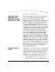
1 Introduction Kodak DryView 8150 Laser Imager The Kodak DryView 8150 Laser Imager is a continuous-tone laser imager with an internal photothermographic film processor. Heat, rather than photo chemicals, is used to develop the film. The Imager receives digital images from medical image source devices (modalities) over a network. The format that the Imager accepts is DICOM. The Imager prints images on Kodak DryView Laser Imaging Film that is packed in 125-sheet cartridges.
Introduction H200_0036CAA 8150 Laser Imager 1-2 7F3319 September 30, 2004
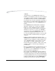
Introduction How the Laser Imager Works The Imager is a network printer connected on a network along with one or more medical imaging devices. It prints images sent over the network from up to twelve medical imaging devices or workstations sending images concurrently. Image Source Devices Modality Network Modality Kodak DryView 8150 Laser Imager H200_0001ba Modality The Imager has hard-disk storage for a large number of digital images.
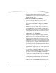
Introduction During normal operation the Imager requires very little operator attention. The Imager prints automatically in response to print requests from the associated image devices. Information sent along with images by the modalities, such as film size, density and priority, control the print operations. Main operator responsibilities are loading film and monitoring for malfunctions. Print Sequence 1-4 Each time the Imager prints a film, the following sequence occurs.
Introduction Receive Tray Film Processor Drum Densitometer Transport Rollers Film Supply Cartridge Platen Rollers Suction Cups Platen Film Feed Rollers Exposure Module Laser Beam H200_0039DA 8100–49C Dashed line is the film path Print Sequence September 30, 2004 7F3319 1-5
Blank Page
2 Operation and Maintenance Operator Control of the Imager During normal operation, the Kodak DryView 8150 Laser Imager receives and automatically prints images sent by modalities over a network. Very little operator control is required. The main operator responsibilities are: • Turn Imager power ON or OFF. • Load film cartridges. • Monitor the number of prints remaining until preventive maintenance is required. • Monitor and control some Imager functions using the Local Panel.
Operation and Maintenance Turning Imager Power ON and OFF Power ON The power switch is located on the back of the Laser Imager. To turn ON the Imager, set the power switch to the "|" position. The Imager performs a power-up self test that takes about five minutes. After some initial boot-up screens, the Local Panel Home screen appears. Power Off Button DVB 14x17 Local Panel Home Screen After the power-up test, the Imager begins a warm-up period that lasts up to 25 minutes.
Operation and Maintenance 2. Touch Yes. The following 2 screens are displayed while the Imager is shutting down software. 3. Set the power switch to the "O" (Off) position.
Operation and Maintenance Power Failures 2-4 In the event of a power loss, the Laser Imager shuts down. Any films in process will not be completed. To restart the Imager after power is restored, turn OFF the power switch on the back of the Imager and then turn it ON. After warming up, the Imager automatically reprints any films that were in process when power was interrupted.
Operation and Maintenance Using the Touch Screen Local Panel The Local Panel displays a collection of screens that you can use to monitor Imager operations and to control some Imager functions. You make menu selections and navigate between Local Panel screens by lightly touching buttons on the touch screen. There is a beep sound each time you touch a button. This sound can be disabled if you wish. CAUTION: Use only your finger when selecting buttons on the screen.
Operation and Maintenance Screen Controls Many of the Local Panel screens have some or all of the buttons on the typical screen below. These buttons are used to navigate between the Local Panel screens and to select items from lists or menus. 9 1 8 2 3 4 7 6 5 Screen Controls 2-6 1 Home button. Returns to the Home screen. 2 Menu button. Displays the Main Menu screen. (See “Main Menu” on page 2-18.) 3 Help button. Displays Help information for the current screen or selected item.
Operation and Maintenance 8 List. Several types of lists appear in Local Panel screens. Examples are menus, lists of print jobs and lists of modalities. You select an item in a list using the Up and Down arrows and the Select button. Selecting an item displays another screen that presents information or choices related to the item you selected. 9 Highlight Bar. This gray bar identifies which one of the items in the list will be selected by the Select button.
Operation and Maintenance Local Panel Help The Local Panel has several types of Help information that explain most of the Local Panel functions. Touch the Help button to see a Help topic. Screen Help Most screens have a Help button that provides Help information for the screen and for buttons and other items on the screen Local Panel Tutorial On the Home screen, touch the Help button to see a list of brief tutorials about the Imager.
Operation and Maintenance Local Panel Passcodes Some Local Panel functions can be performed only by users with passcodes.
Operation and Maintenance Home Screen Description During the power-up self test, this is the first screen you see after the initial start-up screens. The Local Panel always returns to this screen after a few minutes if there are no operator selections on the touch screen. 1 10 2 9 8 3 7 6 4 5 1 Title Bar. Shows the Date and Time. 2 Menu button. Displays the Main Menu.(See “Main Menu” on page 2-18.) 3 Help button. Displays Help information for the current screen.
Operation and Maintenance 6 Film Supply button. Touch to display the Film Supply screen which provides 3 choices: • Open Front Door • Calibrate Film • Run Density Test (See “Film Supply Screen” on page 2-16.) The Film Supply button also displays status information about the film supply within its outline. (See “Film Supply Button Status Information” on page 2-12). 7 Attention Notice.
Operation and Maintenance Film Supply Button Status Information Type of Film Film Size The Film Supply button displays information about the film supply with a combination of messages and color. The most common condition is: Blue Background DVB 14X17 Number of Sheets Remaining This indicates a normal film supply (20 sheets or more). The following table shows all of the status conditions that can be displayed in the Film Supply button.
Operation and Maintenance Film Supply Button Status Combinations September 30, 2004 Message in Film Supply Button Background Explanation Color Fail Flashing Blue and Yellow 7F3319 The film cartridge has failed to open.
Operation and Maintenance Home Screen Status Line The following messages can appear on the Status Line: Message Explanation Printing Printing images from the print queue. Ready Ready to print. No images in the print queue for the currently loaded film size. Self-test The Imager is performing the power-up self test. Warming = The Imager is warming up. The number of minutes until the Imager will be at operating temperature is displayed after the = sign.
Operation and Maintenance Home Screen Attention Notices Three attention notices can appear on the Home Screen: This notice appears when there are 1 or more print jobs in the print queue that require a different size or type of film than is currently loaded. An audible alarm sounds when the number of jobs waiting for media goes from 0 to 1. Touch the screen anywhere to silence the alarm. This notice shows the number of errors that have not yet been corrected.
Operation and Maintenance Film Supply Screen This screen provides three options related to the film supply in the Imager. To display this screen: Home > touch Film Supply button. Open Front Door Unlatches the front door after closing the film cartridge and completing any films in the film path. Calibrate Film Runs a calibration test print. (See “Calibration Prints” on page 2-53.) Run Density Displays the Density Test screen that lets you request a Test SMPTE test print.
Operation and Maintenance Density Test Screen This screen lets you to print one or more SMPTE density test pattern images. You can specify the maximum density. To display this screen: Home > Film Supply button > Run Density Test 1 2 3 September 30, 2004 1 Change Copies. Displays a keypad to change the number of copies of the test print. 2 Change max density. Displays a keypad to change the maximum density of the test print. 3 Print Film (SMPTE). Prints one or more copies of a SMPTE test pattern.
Operation and Maintenance Main Menu You can access most of the Local Panel functions from this menu screen. To display this screen: Touch Menu. 1 6 2 5 4 3 1 System Information button. Displays the System Information Menu screen (see “System Information Menu” on page 2-26). 2 Setup Imager button. Displays the Setup Imager screen where you can enter or adjust parameters such as the Imager network address, hospital name and image quality parameters. See “Setup Imager Screen” on page 2-31.
Operation and Maintenance 4 Service button. Displays the Service screen. Provides several functions used by service technicians. • Most service functions require the Service passcode. (See “Local Panel Passcodes” on page 2-57.) • Refer to “Service Screen” on page 2-42 for information on this screen. September 30, 2004 5 Job Manager button. Leads to several screens that display information about print jobs in various queues. You can also delete print jobs from these screens.
Operation and Maintenance System Functions Screen This screen provides two functions: • Users who have logged on with a passcode can log off from this screen. • Operators can set the Imager either online or offline. When online, the Imager is connected to the network and can receive images from the associated modalities. When offline, the Imager is temporarily disconnected from the network and cannot receive images but jobs in the print queue will continue printing.
Operation and Maintenance September 30, 2004 4 Printing enabled button. Toggles between Printing enabled and Printing disabled. When printing is disabled, the Imager can receive images from the modalities on the network but cannot print from the print queue. Requires Key Operator or Service passcode. 5 Enabled/Disabled Indicator. Green when printing is enabled, yellow when printing is disabled. Requires Key Operator or Service passcode.
Operation and Maintenance Select job Queue Type Screen This screen lists the three job queues and shows the number of print jobs in each queue. To display this screen: Menu > Job Manager 1 2 3 1 Queued to Print. This queue contains all print jobs waiting to be printed except jobs classified as “Unprintable” and “Waiting for media”. 2 Waiting for Media. This queue contains print jobs that require a different size or type of film than is currently in the film tray.
Operation and Maintenance Select Modality Screen This screen shows the number of jobs in a queue from each modality. From this screen you can display a list of the jobs from any one modality. To display this screen: Menu > Job Manager > Queued to Print 1 2 3 1 Name of the queue being displayed: • Queued to print • Waiting for media • Unprintable jobs 2 Select to display a list of jobs from all modalities in the queue. 3 List of modalities.
Operation and Maintenance Job List Screen This screen shows a list of the print jobs within a queue that are all from the same modality. The name of the source modality appears on the screen. To display this screen: Menu > Job Manager > Queued to Print > modality name Name of Queue Modality Name Jobs from the above modality Job List To see detailed information about one of the print jobs on the above screen, highlight the job and then touch Select.
Operation and Maintenance This screen shows information about a single print job that you selected on the previous screen. Users with a Key operator passcode can delete this job from the queue by touching the Delete button. To display this screen: Menu > Job Manager > Queued to Print >modality name > Up/Down to highlight job> Select Job Details Screen 1 2 3 Job Details 4 5 6 7 Job Details September 30, 2004 1 Name of the queue that contains this print job.
Operation and Maintenance System Information Menu From this screen you can select three information screens that display information about the Imager. To display this screen: Menu > System Information System Information Menu 2-26 System Information Displays a screen that identifies the Imager and shows its network address. You may be asked to supply this information if you call Kodak for support. See “System Information Screen” on page 2-27.
Operation and Maintenance System Information Screen This screen displays information that identifies the Imager and shows its network address. To display this screen: Menu > System Information >System Information Versions Screen This screen shows the current versions of software components in the Imager.
Operation and Maintenance Print Counts Screen This screen shows the number of films printed since the Imager was placed in service and the number of prints remaining before the next required PM (Preventative Maintenance session). To display this screen: Menu > System Information > Print Counts Print Counts The "Prints to PM" count is reset to zero when preventive maintenance is performed.
Operation and Maintenance Current Errors Screen This screen lists any errors detected by the software in the Imager during print operations. To display this screen: Menu > Current Errors 1 2 3 Current Errors 1 Error code - identifies the type of error. You will be asked for this code if you call for service. 2 Date and time the error occurred. 3 Abbreviated description of the error.
Operation and Maintenance Error Message Screen This screen appears when the Imager detects an error. It provides information and recommended corrective action for a specific error. You can also display this screen by selecting an error listed on the Current Errors screen. (See page 2-29.) 1 2 3 4 5 6 2-30 7 8 1 Error Code - identifies a specific error. You will be asked for this code if you call for service. 2 Date and time the error occurred. 3 Error description. 4 Corrective action.
Operation and Maintenance Setup Imager Screen This screen is the entry point for all of the Imager configuration functions. These functions are used primarily for installation of the Imager, not for normal operation. Most of these functions require the Service passcode. A few of the Local Panel setup functions are accessible with a Key Operator passcode. To display this screen: Menu > Setup Imager 1 2 3 4 5 6 7 September 30, 2004 1 Network setup.
Operation and Maintenance Edit Network Configuration Screen 2-32 This screen is used to enter the IP Address and other network parameters for the Imager. The Service passcode is required to display this screen. For network setup procedures using this screen, refer to the Installation Manual for the Kodak DryView 8150 Laser Imager.
Operation and Maintenance Date and Time Screen September 30, 2004 This screen is used to edit the date and time displayed on the Local Panel Home screen. The Service passcode is required to access this screen. The date and time can be changed only within a plus or minus 24-hour window, just enough for time zone changes. For date and time setup procedures using this screen, see “Setting Time and Date” on page 2-64.
Operation and Maintenance Select Modality Screen 2-34 Each of the modalities that has printed at least once to the Imager is listed on this screen. Selecting one of the modalities leads to a series of configuration screens that are used to enter and edit image quality parameters for the selected modality. The Service passcode is required to access this screen. For modality setup procedures initiated from this screen, refer to “Chapter 4 Adding a Modality”.
Operation and Maintenance Setup Local Panel Screen From this screen you can access several other screens that allow you to adjust some of the Local Panel properties. To display this screen: Menu > Setup Imager > Local Panel Calibrate touch accuracy - Displays a screen for setting the accuracy of the touch buttons on the Local Panel. Requires the Service passcode. Touch Beep Duration - Displays a screen for setting the duration of the "beep" that sounds when any button is touched.
Operation and Maintenance Edit Service Telephone Number Screen 2-36 From this screen you can enter the Service Telephone that appears on the System Information screen. Requires the Service passcode. To display this screen: Menu > Setup Imager > Edit Service tel.
Operation and Maintenance Restore Configuration This menu choice allows you to restore the Imager configuration parameters from a previously-recorded backup file. The backup file is usually recorded on a floppy disk but can also be recorded on the Imager hard drive or on a remote network drive if accessible on the network. The Service passcode is required. Restore procedure (from floppy disk): You must have a previously-recorded backup disk. 1. From the Home screen, touch Menu. 2. Touch Set Up Imager. 3.
Operation and Maintenance 6. Touch OK. 7. Enter the filename exactly as it is written on the backup disk and touch OK.
Operation and Maintenance 8. Touch Yes. IMPORTANT: Do not touch OK yet. 9. Wait for the front door to open. The Imager first closes the film cartridge, completes any films in process and then unlatches the front door.
Operation and Maintenance Front Door Computer Access Door H200_0034DAA 10. Open the computer access door. 11. Insert the backup diskette into the floppy disk drive. 12. Touch OK. The Imager reads in the backup file. This may take several minutes.
Operation and Maintenance 13. 14. 15. 16. Touch OK. Remove the backup disk from the computer. Close the computer access door and the Imager front door. Log out of the Service Passcode if you are done with service functions: a. Touch the Back arrow to return to the Main Menu. b.Touch System Functions. c. Touch Log off and then Touch OK. 17. Touch the Back arrow twice to return to the Home screen. This completes the restore procedure.
Operation and Maintenance Service Screen This screen is the access point for the Local Panel Service functions. To display this screen: Menu > Service 1 3 2 2-42 1 PM. Enters the date that preventive maintenance is performed and also resets the print-to-PM counters to zero. See page 2-44. Requires the Customer First passcode. 2 Filter Change. Select to enter the date of a filter change. See page 2-43. Requires Key Operator or Service passcode. 3 Ping.
Operation and Maintenance Filter Change - Service Menu Choice Selecting Filter Change on the Service screen displays the screen below. Touch Yes to enter the current date into the Service History log as the date of a filter change. Ping - Service Menu Choice Selecting Ping on the Service screen tests the network connection between the Imager and any modality on the network. You must know the IP address of the modality you wish to test. A keypad appears for entry of the IP address.
Operation and Maintenance If the modality does not respond to the Ping, a message screen informs of the failure PM (Preventive Maintenance)| Service Menu Choice This menu choice performs two functions: Selecting PM on the Service Screen displays the screen below. • Enters the current date into the Service History log as the date of a PM session. • Resets the "Prints to PM" counter to zero. This counter records the number of films of each size printed since the last PM.
Operation and Maintenance When you enter the Customer First passcode and press OK, the PM date is entered and the "Prints to PM" counter is reset. A confirmation screen notifies you that the operation is complete. Image Resizing If the image sent from the modality is too large for the size of film in the Imager, the Imager can resize the image to fit on the film by either of two methods: • Minify - To reduce the image to fit on the selected film size.
Operation and Maintenance Image Resizing Methods Resizing Method Icon Printed on Film Minify Minify Icon The image file is reduced by the removal of pixel data. If the Minify choice was selected when the Imager was setup, the Imager will minify an image if: or Scale Icon 1. The modality sends an image that is too large for the film in the Imager. In this case the Minify icon is printed on the film. 2. The modality requests an image size that the Imager cannot print.
Operation and Maintenance Image Resizing Methods Resizing Method Icon Printed on Film Crop (continued) Cropping allows “true size” printing for larger images. True size printing provides a common scale between images captured on analog systems (those which use medical x-ray film exposed by phosphor screens in cassettes) and printed digital images. The anatomical area of interest is printed at the same size that it is captured on the analog system.
Operation and Maintenance Operation Opening the Front Door During normal operation you may need to open the front door of the Imager to insert or remove the film cartridge, clear a film jam or change the charcoal filter. To open the front door while power is ON: 1. On the Home screen, touch the Film Supply button. Film Supply Button 2. Touch Open Front Door. The front door opens after the Imager closes the film cartridge and completes printing any films in process.
Operation and Maintenance the front door will not unlatch. An error message appears to announce this error. The Error Message screen includes an Open Door button that will force the door open even though the film cartridge remains open. Opening the Front Door Manually If the Imager power is OFF or if opening the front door from the Local Panel fails, you can use the manual latch to open the front door. NOTE: If you open the door manually, the film cartridge does not close automatically.
Operation and Maintenance 4. If the film cartridge is open, close the cover immediately. a. Clear any films that may be jammed in the cartridge area. b.Turn the rollback knob counterclockwise to close the cartridge.
Operation and Maintenance Opening the Hood You will have to open the hood to clear film jams in the developer area or to open the front door manually. Output Tray Hood Support Rod Grasp Hood Here CAUTION: Whenever you raise or lower the hood, grasp the hood only in the area of the recessed slot below the Local Panel to avoid pinching your fingers. To open the hood: 1. Remove any films in the output tray. 2. Grasp the hood at the recessed slot below the Local Panel. 3.
Operation and Maintenance Loading and Removing Film Cartridges To load a film cartridge: 1. Open the front door. (See “Opening the Front Door” on page 2-48.) 2. Insert the cartridge into the slot as shown in the illustration. 3. Slide the cartridge fully into the Imager. 4. Close the front door. After you close the door, the Imager opens the film cartridge.
Operation and Maintenance Recycling Empty Film Cartridges In some regions you can return your empty Kodak DryView Film Cartridges to Kodak for reuse and recycling. Contact your Kodak sales representative to determine the availability of the film cartridge recycling program in your region. Returned cartridges are carefully inspected. Only components that meet strict quality standards are reused. Components that do not meet the standards are sent to recycling centers for reclamation.
Operation and Maintenance 2. Touch Calibrate Film. 3. Touch Yes then OK. The Imager will print a calibration film before printing any jobs in the print queue that have not yet started printing and will interrupt a multi-sheet print job to run a calibration print. Requesting a Density Test The Imager can print an internally generated density test print with a SMPTE pattern. Density test prints are often used as a quality assurance tool to verify the uniformity of films printed by the Imager.
Operation and Maintenance 3. Touch Run Density Test. 4. If you want to change the maximum density value, highlight Change Max Density and touch Select.
Operation and Maintenance 5. Enter the maximum density value that you want and touch OK. (Upper limit: 3.1.) The Density test screen reappears. 6. To print more than one copy, highlight Change copies and touch Select. 7. On the keypad, enter the number of copies and touch OK. 8. Highlight Print film and touch Select. The density test print is placed at the front of the print queue.
Operation and Maintenance Local Panel Passcodes There are four levels of access to the Local Panel. Three of these access levels require passcodes. Operator Level Passcode not required. Operators can access most Local Panel features except for Service functions and Imager setup functions. Key Operator Level Requires a Key Operator User ID and passcode. In addition to operator-level functions, key operators can: • Delete print jobs from the Imager.
Operation and Maintenance Setting Up Passcodes Key Operator Passcodes and the Service passcode are set up on the Passcode Entry screen. Each passcode must be accompanied by a User ID. Only a user with the Service passcode can enter Key Operator passcodes or change the Service passcode. The Customer First passcode cannot be changed and is not displayed on the Passcode Entry Screen. 2 1 Passcode Entry Screen Logging On to the Local Panel with a passcode 2-58 1 User IDs.
Operation and Maintenance Logging Off Users who have logged on with any passcode can log off by touching the Logoff button on the System Functions screen. There is also a passcode timeout feature that automatically logs a user off if the are no inputs on the touch screen for 2 minutes. This automatic logoff does not apply when any of the Setup Imager screens are displayed or when an Error Message screen is displayed.
Operation and Maintenance Adjusting Local Panel Preferences Key Operators can change the following Local Panel properties: • Volume of "beep" that sounds when you touch any button • Backlight intensity • Audible alarm volume • Audible alarm - enable or disable A Key Operator passcode is required to change these properties. Displaying the Setup Local Panel Screen You make all changes to the Local Panel properties from the Setup Local Panel screen. To navigate to this screen: 1.
Operation and Maintenance Set Up Local Panel Screen Adjust Touch Beep Duration To adjust beep duration: 1. On the Setup Local Panel screen, highlight Touch Beep Duration. 2. Touch Select. 3. Touch the Up or Down arrows to change duration of the beep sound. You will hear a beep each time you touch the Up or Down arrows. 4. Touch the Back arrow to return to the Setup Local Panel screen.
Operation and Maintenance Adjust Backlight Intensity To increase or decrease the backlight intensity: 1. On the Setup Local Panel screen (page 2-61), highlight Backlight intensity. 2. Touch Select. 3. Touch the Up or Down arrows to change the intensity. 4. Touch the Back arrow to return to the Setup Local Panel screen.
Operation and Maintenance Adjust the Audible Alarm The audible alarm is a series of tone pulses that sound when an error occurs or when Waiting for Media appears on the Home screen. You can adjust the duration of the tone pulses. 1. On the Setup Local Panel screen (page 2-61), highlight Audible Alarm. 2. Touch Select. 3. Touch the Alarm Enabled button to enable or disable the alarm. Touching the button repeatedly alternates between enabled and disabled. 4.
Operation and Maintenance Setting Time and Date The time and date appear in the Home screen. The time, time format, date and date format can be set. The Service Passcode is required. The combination of date and time can be increased or decreased by no more than 24 hours. Date and Time • Formats for time include AM/PM or 24-hour (military). • Formats for date include – MM_DD_YYYY – DD_MM_YYYY – YYYY_MM_DD To change the time, time format, date or date format: 1. Touch the Menu button. 2.
Operation and Maintenance 4. Highlight Date and Time; then touch Select. 5. A keypad will prompt for the for the Service user name and then the Service passcode if you are not logged in. 6. To change the date format: a. Highlight Date Format. b. Touch Select to change the date format. Each time you touch Select, the date format changes.
Operation and Maintenance 7. To change the date: a. Highlight Date and touch Select. A keypad appears on the Local Panel. b. Enter the new date and touch OK. The new date appears on the Date Time screen. 8. To change the time format: a. Highlight Time Format and touch Select. b. Touch Select to change the time format. There are two time formats (AM/PM and 24-hour). Each time you touch Select, the time format changes to the alternate format. 9. To change the time setting: a.
Operation and Maintenance Operator Maintenance Cleaning the Laser Imager Clean the outside surfaces of the Laser Imager as necessary. Use a soft cloth with warm water and mild soap. CAUTION: Do not use isopropyl alcohol to clean the exterior surfaces of the Laser Imager. Isopropyl alcohol can dissolve the exterior paint on the Laser Imager. Replacing the Charcoal Filter Kodak DryView Laser Imaging Film emits a slight odor when it is heated during the developing process.
Operation and Maintenance if the odor becomes noticeable or when "Preventive Maintenance" appears on the Home screen. CAUTION: The charcoal filter is considered non-hazardous waste by the US EPA Resource Recovery Act. Under RCRA, you may dispose of filters in a landfill or incinerator with energy recovery in a municipal, commercial or industrial facility. Contact your state or local government to determine if additional disposal requirements apply.
Operation and Maintenance 5. Pull the retaining clip forward and down to lock the filter in place. 6. Close the front door. 7. Change the Filter Change Date in the Service log. a. On the Home screen touch Menu. b.Touch Service. c. Touch Filter Change and then Yes. The current date is entered into the log as the Filter Change Date.
Operation and Maintenance Blank Page 2-70 7F3319 September 30, 2004