
Install Instructions
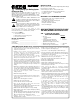


Figura 4
Sellador de
extremos
Distancia entre las vueltas
Cable Calentador Freeze Free
Válvula
Cinta
COMO DETERMINAR EL LARGO DE CABLE QUE
NECESITARA
(LARGO MAXIMO DEL CIRCUITO: 75 PIES)
PASO 1 OBTENGA LA SIGUIENTE INFORMACION
NECESARIA
• Dimensiones de la tubería
• Diámetro externo
• Largo
• Temperatura más baja esperada (no
considere la sensación térmica: está calculada
en el cuadro de selección de longitudes)
• Número de válvulas y llaves
• Distancia desde la tubería hasta el tomacorriente
INSTRUCCIONES IMPORTANTES DE SEGURIDAD
• Los cables calentadores DEBEN instalarse de acuerdo con lo establecido
en TODOS los códigos nacionales, estatales y locales. Consulte con el
inspector local de electricidad acerca de los detalles especícos.
• Tenga SIEMPRE cuidado al instalar y utilizar el sistema de calefacción
de tuberías FreezedFree. Para su seguridad, siga CON CUIDADO y
entienda las instrucciones y las advertencias proporcionadas.
• El enchufe y el aislante térmico de bra de vidrio FreezedFree con
selladura por vapor deben mantenerse secos e impermeabilizados
para evitar posibles descargas eléctricas o incendios.
• Utilice el sistema FreezedFree UNICAMENTE en tuberías de agua domésticas
de metal y de plástico (como las de PVC o polibutileno). NUNCA lo
utilice en tuberías exibles de vinilo (mangueras para jardín), en tuberías
subterráneas, en tuberías que conduzcan sustancias líquidas que no sean
agua, o en aplicaciones de calefacción (como la descongelación de techos
y canaletas o el derretimiento de la nieve de las entradas de garaje).
• NUNCA exponga un cable FreezedFree a temperaturas que SUPEREN los
150°F (66°C). Esto acortará su duración. ANTES de instalarlo en tuberías de
agua caliente, ponga SIEMPRE el termostato del calentador de agua a 150°F
(66°C) (temperatura baja o media en la mayoría de los termostatos).
• Para realizar las conexiones, utilice UNICAMENTE el juego de enchufe
con fusible (10802 ó 10803).
• NUNCA modique el enchufé de NINGUNA manera.
• Para evitar cortocircuitos, NUNCA retuerza los alambres del cable
FreezedFree para unirlos NI permita que se toquen entre sí o que toquen
el trenzado exterior.
• Quite SIEMPRE de la calefacción la cinta o el aislante que estén
desgastados.
• Mantenga los extremos de los cables SIEMPRE limpios y secos.
• Selle el cable UNICAMENTE al sellador de extremos proporcionado.
• Corte la funda del cable FreezedFree UNICAMENTE en los extremos
cuando una el enchufe con fusible con el sellador de extremos.
• NUNCA corte la funda plástica del cable FreezedFree ni haga muescas en
ésta, ni permita que se deteriore. El trenzado DEBE permanecer intacto.
• NUNCA instale el cable en un sitio donde pueda quedar expuesto a
golpes o cortaduras.
• NUNCA instale el cable en un sitio donde pueda dañarse debido a la
frotación contra supercies ásperas.
• ANTES de instalar el cable FreezedFree, utilice una lima para eliminar de la
tubería TODOS los bordes losos que puedan dañarlo. El cable DEBE estar en
contacto UNICAMENTE con supercies de tuberías suaves y no abrasivas.
• Proteja SIEMPRE el sistema EN SU TOTALIDAD contra posibles daños
causados por animales o golpes.
• NUNCA utilice clavos, abrazaderas de metal, alambres u otros dispositivos
que puedan cortar el cable para sujetarlo a lo largo de la tubería.
• Utilice únicamente cinta de vinilo o de bra de vidrio de ½ pulgada o 1
pulgada para unir el cable a la tubería.
• Inspeccione el cable FreezedFree para comprobar que no esté dañado CADA
VEZ que lo enchufe. Si lo deja enchufado durante todo el año, inspecciónelo
POR LO MENOS une vez al año o CADA vez que sospeche que puede
estar dañado.
• Si ve en el cable un corte, una mella o algún punto deteriorado, desconnecte
el sistema de INMEDIATO y reemplace el cable.
• There are NO serviceable parts in the FreezedFree Cable System.
• NUNCA empalme un cable dañado.
• NUNCA repare un cable dañado.
• ALWAYS replace a damaged cable with a new one.
• Reemplace SIEMPRE las cubiertas resistentes al agua y los aislantes
dañados luego de CADA inspección del cable.
• Conecte el enchufe UNICAMENTE a un tomacorriente instalado según el
Código Eléctrico Nacional (o la CEC) Y protegido contra la lluvia u otras
precipitaciones de agua.
• NUNCA instale o utilice el cable FreezedFree en sitios donde haya materiales,
líquidos o vapores inamables. Si el cable se corta durante la conexión del
sistema, el riesgo de que se produzca un incendio aumentará.
• Use SIEMPRE un dispositivo de protección contra fallas conectado a
tierra (GFPD) para reducir el peligro de incendios ocasionado por cables
calentadores dañados o mal instalados. La corriente de falla eléctrica
ocasionada por un cable dañado o mal instalado PUEDE NO SER
SUFICIENTE para activar un interruptor de circuitos convencional.
• Si NO sabe si su circuito eléctrico está protegido por un GFPD, SIEMPRE
consulte con un electricista. Muchos receptáculos de cinta térmica para
casas móviles NO están protegidos por un GFPD. Hay a su disposición un
GFPD con conexión de cable para aplicaciones en exteriores en Easy Heat
(catálogo N.
o
HCP1).
• En aplicaciones en casas móviles, conecte el enchufe UNICAMENTE a
tomacorrientes eléctricos ubicados DEBAJO de éstas. El tomacorriente DEBE
estar en un sitio donde esté protegido y seco, ya que el enchufe NO es
impermeable. NUNCA utilice una extensión eléctrica.
• Para evitar que el cable se dañe y que haya peligro de incendios o
descargas eléctricas, coloque la etiqueta de "Precaución" proporcionada
con el juego de enchufe FreezedFree (10802 y 10803) en algún lugar
del sistema terminado en el que pueda verse CON FACILIDAD. Esta etiqueta
de "Precaución" constituye un REQUISITIO del Código Eléctrico Nacional.
PASO 4 COMO ENSEMBLAR E INSTALAR EL CABLE
Y EL JUEGO DE ENCHUFE CON FUSIBLE
INSTALACION DEL SELLADOR DE EXTREMOS
4.a. Recorte CON PROLIJIDAD el extremo
del cable.
4.b. 1. Utilice un lápiz o un destornillador
para desenredar y retraer el trenzado
1 pulgada desde el extremo del cable.
2. Retuerza el trenzado, apriételo bien
y forme con
él una espiral.
4.c. 1. Coloque cinta en el trenzado con forma de
espiral y adhiéralo al extremo del cable
trenzado.
2. Pushing rmly, insert the cable into
the end seal all the way (at least
3
/
4
").
Some gel may ooze out. Do not
attempt to wipe off.
NO RETUERZA EL SELLADOR DE EXTREMOS DURANTE SU INSERCION O
LUEGO DE ESTA. NO VUELVA A UTILIZAR UN SELLADOR DE EXTREMOS.
Para evitar cortocircuitos, NUNCA retuerza los alambres del cable FreezedFree para
unirlos NI permita que se toquen entre sí o que toquen el trenzado exterrior.
Sistema de calefacción para tuberías con regulación automática
HOJA DE INSTRUCCIONES
ESTE PRODUCTO HA SIDO DISEÑADO PARA SER UTILIZADO UNICAMENTE A
FIN DE PROTEGER LAS TUBERIAS DE AGUA CONTRA HELADAS. LA INSTALA-
CION, EL USO Y/O EL MANTENIMIENTO INCORRECTO O EL DAÑO DEL CABLE
CALENTADOR ELECTRICO PUEDEN OCASIONAR INCENDIOS, DESCARGAS
ELECTRICAS Y/O EL CONGELAMIENTO DE LAS TUBERIAS.
ESTE ES UN SIMBOLO DE ALERTA DE SEGURIDAD. CUANDO VEA
UNO, SIEMPRE LEA CON CUIDADO Y ENTIENDA LAS ADVER-
TENCIAS QUE LO SIGUEN. SEA CONSCIENTE DE QUE EXISTE LA
POSIBILIDAD DE SUFRIR LESIONES GRAVES O MORTALES
.
a
ADVERTENCIA
Utilice este producto UNICAMENTE en tuberías de suministro de
agua y de desagüe. SIEMPRE lea Y siga las instrucciones impor-
tantes de seguridad. Si no lo hace, puede sufrir lesiones graves o
mortales debido a un incendio o a desgargas eléctricas.
ANTES DE COMENZAR
Asegúrese de que el largo del cable calentador sea ADECUADO para la tubería
que va a proteger (vea el cuadro N.
o
1 o N.
o
2).
Su kit de enchufe fusibleado (10802 ó10803) debe contener:
• un cuerpo de enchufe con un fusible incorporado que no pueda reemplazarse
• un sellador de extremos a presión • etiquetas de “PRECAUCION"
• sujetadores para cable (2 piezas).
HERRAMIENTAS Y MATERIALES ADICIONALES NECESARIOS
• Cinta para aplicaciones (catálogo HCA) o cinta de electricista similar a la
cinta Scotch 44 ó 33.
• Aislante para tuberías de bra de cidrio de 1/2" pulgada con selladura
por vapor.
• Cortadores de alambre o tijeras grandes.
• Destornilladores Phillips N.
o
2 y planos.
• Regla o cinta para medir.
Ejemplo
La tubería que usará es de plástico, mide 12 pies y tiene una válvula de bola
Necesitará 2,5 pies de cable por pie de tubería plástica, como se indica en
el paso 2 de arriba.
Realice el cálculo (12 pies x 2,5) y súmele al resultado 1 pie para la
válvula de bola
Largo total del cable = 31 pies
EL LARGO MAXIMO DEL CABLE ES DE 75 PIES. SI SE UTILIZA UN CABLE
MAS LARGO, EL FUSIBLE INTERNO PUEDE QUEMARSE.
PASO 2
REMITASE A LOS CUADROS DE SELECCION DE LONGITUDES
En estos cuadros, encontrará el largo de cable que necesitará por cada pie
de tubería y también la distancia que deberá dejar entre cada vuelta de cable
de la tubería.
COMO UTILIZAR EL CUADRO DE SELECCION DE LONGITUDES
Elija el cuadro N.
o
1 o N.
o
2 según el tipo de tubería que utilizará (de plástico
o de metal). Lea hacia abajo para hallar el diámetro de tubería adecuado y
hacia la derecha para hallar la casilla con la temperatura más baja que se
espera. El primer número que aparece en la casilla representa la longitud (en
pies) de cable que necesitará por cada pie de tubería. El segundo número
representa la distancia recomendada entre cada vuelta de cable de la tubería.
La abreviatura "str" indica que el cable debe colocarse en línea recta y no en
forma de espiral alrededor de la tubería (vea el paso #6).
Ejemplo
• El diámetro de la tubería es de 1
1
/
2
de pulgada
• La temperatura más baja que se espera es de -20°F (-29°C)
• El largo de la tubería es de 12 pies
Según el cuadro N.
o
1:
• Necesitará 2,5 pies de cable por cada pie de tubería (tuberías de metal)
Según el cuadro N.
o
2:
• Necesitará 1,8 pies de cable por cada pie de tubería (tuberías de
metal).
Selección de longitudes del cuadro N.
o
2 para tuberías de metal
(si se usa un aislante de
1
/
2
pulgada)
Tubería Temperatura más baja que se espera
Diámetro
+20°F/-7°C 0°F/-18°C -20°F/-29°C -40°F/-40°C -60°F/-51°C
1
/
2
" 1' 1' 1' 1.3' 1.7'
str str str 3
1
/
8
" 2"
3
/
4
" 1' 1' 1.1' 1.5' 2'
str str
7
1
/
4
" 3"
2
"
1" 1' 1' 1.3' 1.8' 2.4'
str 5" 5" 2
3
/
4
" 1
7
/
8
"
1
1
/
4
" 1' 1.1' 1.6' 2.1' 2.9'
str
11
1
/
2
"
4
1
/
4
"
2
7
/
8
" 1
7
/
8
"
1
1
/
2
" 1' 1.2' 1.8' 2.4' 3.2'
str 9" 4" 2
3
/
4
" 1
7
/
8
"
2" 1' 1.5' 2.2' 2.8' 3.9'
str
6
5
/
8
"
3
3
/
4
"
2
7
/
8
"
2
"
a
PASO 3 CALCULE EL LARGO EXACTO PARA EL CABLE
CALENTADOR QUE NECESITARA
Multiplique el largo de cable necesario para cada pie de tubería que
utilizará. Agregue un pie por cada válvula ubicada en la línea. El largo
máximo del cable es de 75 pies. Para cables de más de 75 pies de largo,
use dos cables.
(Largo de cable necesario para cada pie de tubería x largo de la tubería)
+ 1 pie más por cada válvula o llave
= largo total del cable
a
PASO 5 INSTALACION DEL ENCHUFE
NUNCA INTENTE ENSEMBLAR UN ENCHUFE O UN SELLADOR
DE EXTREMOS MIENTRAS EL ENCHUFE ESTE CONECTADO A LA
FUENTE DE ENERGIA ELECTRICA.
Antes de extraer los tornillos de la cubierta, enchufe el cable de alimentación al
tomacorriente de 120 voltios para comprobar que funcione la luz indicadora
de encendido. Si la luz no se enciende, no instale el cable; devuelva el enchufe
a su vendedor para que lo reemplace.
5.b. 1. Aoje dos tornillos de ensamblaje (approximadamente 1/4 de
pulgada).
2. NO extraiga por completo los tornillos de ensamblaje (vea
la gure 2.a).
Figura 1
Luz de encendido
Tornillos de la
cubierta (2)
5.a. 1. Desconecte el cable
d e a l i m e n t a c i ó n
del tomacorriente.
Ex t r ai g a los d o s
t o r n i l l o s d e l a
cu bi er ta . ( Vea la
gura 1)
Figure 2a
cable
trenzado
tornillos de
ensamblaje (2)
Tira de
conexión a tierra
cable
Accesorio
del tornillo
de montaje
3. Introdúzcalo hasta que la funda amarilla se vea desde la abertura,
como se muestra en la gura 2.b.
4. El trenzado con conexión a tierra NO DEBE introducirse en la abertura
del accesorio del tornillo de ensamblaje y entrar en contacto con un
tornillo de ensamblaje que conduzca corriente cuando el enchufe
vuelva a ensamblarse y el sistema vuelva a funcionar.
Figure 2.b
5d. Ajuste los dos tornillos del emsamblaje hasta que queden bien apreta-
dos contra las supercies de metal de la parte superior del accesorio
del tornillo de ensamblaje (5 libras por pulgada de torsión).
5e. Asegúrese de que el trenzado con conexión a tierra que cubre el cable esté
en contacto con la tira con conexión a tierra cuando vuelva a ensamblar
el enchufe. El contacto entre el trenzado y la tira con conexión a tierra
completa el circuito de conexión a tierra del sistema. Vea la gura 3.
5.f. Cierre la cubierta e inserte los dos tornillos de ésta. Ajuste los dos
tornillos de la cubierta hasta que queden bien apretados contra las
supercies plásticas de sus aberturas.
Figura 3
COMO INSTALAR EL CABLE EN LA TUBERIA
PASO 6 UNION DEL CABLE A LA TUBERIA
6.a. Comenzando por el extremo del enchufe, colóquelo de modo que forme
una espiral alrededor de la tubería o extiéndalo en línea recta a lo largo
de ésta, como se indica en el cuadro de selección de longitudes. Monte
el enchufe en la tubería con revestimientos para juntas de plástico.
Método de colocación en forma de espiral
Coloque el cable en forma de espiral alrededor de la supercie externa de la
tubería. ASEGURESE de dejar la distancia necesaria entre las vueltas de cable,
como se indica en el cuadro de selección de longitudes. Antes de unir el cable
a la tubería, márquela donde se establezca la distancia necesaria entre las
vueltas de cable. (Vea la gura 4).
Método de colocación en línea recta
Con la tubería al nivel de los ojos, coloque el cable extendiéndolo en línea
recta en forma paralela a la parte INFERIOR de la tubería y a aproximada-
mente 1/3 de la distancia entre ésta y la parte superior. (Vea la gura 5)
6.b. Proporcione más calor en las válvulas y
en las llaves envolviéndolas con el pie
adicional de cable, que superpondrá
según sea necesario.
5.c. 1. Recorte con prolijidad
1 pulgada de cable.
2. Inserte el cable trenzado
en la abertura del
accesorio del tornillo
de ensamblaje (túnel)
Haga que el trenzado
se deslice hacia atrás
a med ida q ue se
introduzca el cable.
COMPROBANTE DE COMPRA
Fecha de la compra _______________________________
Lugar de compra _________________________________
Instalado por ______________________________________
Fecha de instalación ________________________________
Para obtener más información o el nombre de su proveedor de sistemas
FreezedFree más cercano, llame de lunes a viernes de 9 a.m. a 5 p.m. al
800/537-4732 (EUA), al 800/794-3766 (Canadá).
Estas instrucciones deben:
• Guardarse para ser consultadas en el futuro.
• Estar a disposición del USUARIO de los cables calentadores
• Entregarse a futuros propietarios
PASO 7 INSTALACION DEL AISLANTE
El aislante térmico protege el cable FreezedFree y evita que la tubería se
congele.
7.a. ANTES de instalar el aislante, ASEGURESE de que el cable FreezedFree
NO tenga daños (mellas o cortes) y de que el trenzado esté intacto.
7.b. Cubra la tubería, el cable, las conexiones, las válvulas y las llaves con
aislante de bra de vidrio de ½ pulgada limpio
y seco. NO DEJE EL CABLE EXPUESTO (Vea la
gura 6). Si existen posibilidades de que la funda
se dañe, proteja el cable expuesto con aislante u
otros revestimientos. No cubra la luz indicadora
de encendido con aislante u otro revestimiento.
• Utilice UNICAMENTE materiales aislantes resistentes al fuego como el
revestimiento de bra de vidrio.
• ASEGURESE de que el aislante de bra de vidrio quede impermeabilizado
colocando un manguito hermético o una barrera contra el vapor (como
un revestimiento de polietileno) alrededor de éste siempre que exista la
posibilidad de que entre en contacto con el agua.
7.c. Coloque la etiqueta de “Precaución” sobre la tubería cubierta con aislante,
en un lugar en el que pueda verse con facilidad. Si desea más etiquetas,
llame gratis al 800/562-6587.
Figura 6
6.c. Sujete el cable en la tubería colocando
cinta a intervalos de SEIS PULGADAS.
Si sobra cable en el extremo de la
tubería, REPLIEGUELO y sujételo a
lo largo de la tubería en un sitio
donde el aislante pueda cubrirlo POR
COMPLETO. Aségurese de que el
cable esté rmemente asegurado en la
tubería.
6.d. Un con cinta el sellador de extremos a
la tubería.
6.e. Ya sea en un brida cocodrilo o en un
tubo vertical móviles, NUNCA instale
el sellador de extremos del cable
FreezedFree en un punto en el que
normalmente pueda sumergirse.
COMO HACER QUE EL CABLE FREEZEdFREE
FUNCIONE Y COMO REALIZAR EL MANTENIMIENTO
PASO 8 PUESTA EN FUNCIONAMIENTO DEL
SISTEMA FREEZEdFREE
Once installation is complete, plug the cable into a 120 volt AC outlet.
Do not use any water for about an hour and then turn on a water tap
on the FreezedFree protected pipe and test the temperature of the water.
It should feel warm almost immediately as the water heated by the FreezedFree
Cable runs through the pipe.
PASO 9 GUIA PARA LA SOLUCION DE PROBLEMAS
Si durante el paso 8 el agua no está caliente cuando se abre el grifo o si
en algún momento se enfría la tubería protegida con FreezedFree, verique
visualmente la luz de encendido del enchufe para ver si el cable recibe en-
ergía. Si la luz está apagada, desenchufe el cable FreezedFree y asegúrese
y encárguese de que se cumpla lo siguiente:
9.a. ¿El tomacorriente recibe alimentación eléctrica?
9.b. ¿El enchufe con fusible está conectado en forma correcta?
9.c. ¿Está seco el aislante de bra de vidrio?
9.d. ¿Ha instalado la cantidad de cable adecuada para el diámetro de la tubería,
para la temperatura más baja que se espera y para el grosor del aislante?
ADVERTENCIA
SI ALGUNA PARTE del sistema del cable FreezedFree Cable está
dañada, signica que el SISTEMA está dañado EN SU TOTALIDAD.
NUNCA intente reparar UNA PARTE del sistema del cable, ni siquiera
un enchufe con un fusible quemado. Reemplace SIEMPRE un sistema
dañado por uno NUEVO.
a
PASO 10 INSPECCIONES ESTACIONALES
Aunque el sistema FreezedFree puede dejarse conectado durante todo el año,
ahorrará energía si lo desconecta durante las temporadas en las que no haya
heladas. De todas formas, CADA VEZ que lo conecte, O POR LO MENOS una
vez al año (si lo deja conectado), o CADA vez que sospeche que pueda estar
dañado, realice las siguientes vericaciones:
10.a. Revise el sistema FreezedFree EN SU TOTALIDAD para ver si está
dañado. TENGA EN CUENTA que esto puede notarse si el aislante está
decolorado o dañado.
10.b. Revise TODOS los tramos expuestos del cable para ver si tienen cortes,
mellas, abrasión, mordeduras de animales u otros daños.
10.c. Si encuentra daños, REEMPLACE DE INMEDIATO el sistema del cable
por uno nuevo.
10.d. Luego de realizar una INSPECCION EXHAUSTIVA, repita los pasos
8 y 9.
GARANTIA LIMITADA Y RESPONSABILIDAD
En Easy Heat, garantizamos que si hay algún defecto en los materiales o en la fabricación
de este producto durante los primeros doce (12) meses desde la fecha de compra,
reemplazaremos el producto por un modelo equivalente, sin incluir los costos de mano
de obra ni ningún otro costo de instalación..
Nuestra obligación de reemplazar el producto según lo establecido anteriormente se
limita a los casos en los que: (a) la instalción del producto se haya realizado según
las especicaciones detalladas en nuestras instrucctiones de instalación, y (b) el
producto no haya sufrido daños ocasionados por actividades mecánicas o eléctricas
no relacionadas.
El reemplazo del producto según lo establecido anteriormente será el único y
exclusivo resarcimiento en caso de incumplimiento de esta garantía. Esta garantía
limitada no cubre ningún costo de servicios relacionados con la reparación o el
reemplazo del cable.
No seremos responsables de ningún daño incidental, especial o causal que derive
del incumplimiento de esta garantía o de otra causa, ya sea que dicho daño haya
sido ocasionado por negligencia o no. Algunos estados no permiten la exclusión o
limitación de daños causales o incidentales, por lo tanto, es posible que la limitación o
exclusión antes mencionada no se aplique en su caso.
La garantía precedente es exclusiva, y no existe ninguna otra garantía relacionada con
la descripción o la calidad de este producto. Ninguna armación de hecho ni ninguna
promesa hecha por nosotros, ya sea de palabra o por acciones, constituirá una garantía.
Si se le ha mostrado algún modelo o alguna muestra del producto, tal modelo o muestra
fueron usados sólo para ejemplicar la calidad y el tipo general del producto y no para
representar que el producto sería necesariamente de ese tipo o naturaleza. Ningún agente,
empleado o representante nuestro tiene autoridad para vincularnos a las afirmaciones,
representaciones o garantías relacionadas con los productos vendidos, a menos que
dichas afirmaciones, representaciones o garantías se incorporen específicamente
por medio de un contrato escrito.
Cualquier garantía implícita de calidad e idoneidad para un fin determinado que
pueda surgir en relación con la venta de este producto se limitará a la duración de
doce (12) meses a partir de la fecha de compra. Negamos todas las demás garantías
implícitas
, a menos que esté prohibido por la ley. En tal caso, dichas garantías implícitas
quedarán sin efecto en el plazo más corto posible que establezca la ley vigente. Algunos
estados no permiten limitaciones en cuanto a la duración de las garantías implícitas, por
lo tanto, es posible que le limitación anterior no se aplique en su caso.
Est garantía le proporciona derechos legales especícos. Además, usted tiene otros
derechos que varían según las leyes de cada estado o provincia.
Para obtener un reemplazo de acuerdo con los términos y condiciones de esta garantía,
debe devolver el producto o el componente que no funciona, con el comprobante de
compra, a Easy Heat, a la dirección que se indica en esta garantía. El comprador es
responsable de todos los costos ocasionados por la remoción y la reinstalación del
producto y debe pagar el envío a la fábrica o al lugar de compra.
En los EE. UU. En Canadá
Heating Cable Warranty Dept. Heating Cable Warranty Dept.
2 Connecticut South Drive 99 Union Street
East Granby, CT 06026 Elmira ON N3B 3L7
14047-001 Rev. 9 ©2009 Easy Heat
La UL aprueba únicamente los sistemas de cables calentadores Freeze
Free
que se utilicen para la calefacción de casas móviles por medio de tuberías,
y las siguientes limitaciones DEBEN tenerse en cuenta:
• En exteriores, el sistema
Freeze
Free
NO puede instalarse en un sitio
que no sea DEBAJO de una casa móvil.
• NUNCA DEBE conectarse a un tomacorriente que esté expuesto.
• En exteriores, NUNCA DEBE conectarse a un tomacorriente que no se halle
DEBAJO de una casa móvil.
• NUNCA utilice una extensión eléctrica para alcanzar el tomacorriente.
• De acuerdo con el Código Eléctrico Nacional, los tomacorrientes para
sistemas de cables calentadores ubicados debajo de las casas móviles
DEBEN estar DENTRO de los 2 pies de distancia de la entrada
de agua fría.
• Conecte el sistema
Freeze
Free UNICAMENTE a un tomacorriente que
cumpla con este requisito.
www.easyheat.com
C a b l e c a l e n t a d o r
9 5 2 S par a tuberías
d e c a s a s m ó v i l e s
Sistema
mencionado
Ejemplo
• TUBERIA de
1 ½ pulgadas
• 12 pies
• -20°F/-29°C
• 1 válvula de bola
• 2 pies
Largo de cable necesario
por pie de
tubería
Distancia
entre les vueltas de
cable en espiral
“str” indica que el
cable debe ir en
línea recta (no
en espiral)
Selección de longitudes del cuadro N.
o
1 para tuberías de plástico
(si se usa un aislante de
1
/
2
pulgada)
Tubería Temperatura más baja que se espera
Diámetro
+20°F/-7°C 0°F/-18°C -20°F/-29°C -40°F/-40°C -60°F/-51°C
1
/
2
" 1' 1' 1.5' 2' 2.4'
str str 2
3
/
8
" 1
1
/
2
" 1
1
/
4
"
3
/
4
" 1' 1.1' 1.7' 2.3' 2.9'
str
7
1
/
4
" 2
3
/
8
"
1
1
/
2
"
1
1
/
4
"
1" 1' 1.3' 2' 2.7' 3.3'
str 5" 2
3
/
8
" 1
5
/
8
" 1
3
/
8
"
1
1
/
4
" 1' 1.6' 2.3' 3.2' 4.1'
str 4
1
/
4
" 2
1
/
2
" 1
3
/
4
" 1
3
/
8
"
1
1
/
2
" 1' 1.8' 2.5' 3.6' 4.7'
str 4" 2
5
/
8
" 1
3
/
4
" 1
3
/
8
"
2" 1' 2.1' 3' 4.3' 5.4'
str
4
"
2
5
/
8
"
1
3
/
4
"
1
1
/
8
"
Sellador de
extremos
Brida
cocodrilo
Tubería
Nivel del
suelo
Figura 5
Sellador de
Extremos
Válvula
Cinta
Cable Calentador Freeze Free
IMPORTANT SAFETY INSTRUCTIONS
• Heating cables MUST be installed in compliance with ALL Na-
tional, State and Local codes. Check with your local electrical
inspector for specic details.
• ALWAY S ex erc is e p ro pe r c ar e a nd c au t io n dur in g
insta l l a t i o n and use of the F r e e z e d F r ee Pipe Heat-
ing System. CAREFULLY follow and understand t h e
instructions and warnings provided for your safety.
• T h e F r e e z e d F r e e p l u g a n d f i b e r g l a s s t h e r m a l
ins ula tio n w i th va p or sea l m ust be ke p t d ry an d
waterproof to avoid possible electrical shock or re.
• ONLY use the FreezedFree System on metal and plastic domestic
water pipes (such as PVC or polybutylene). NEVER use product
on exible vinyl tubing (garden hose), on buried pipes, on pipes
carrying any uid other than water, or ANY non-pipe heating
applications such as roof and gutter de-icing or driveway snow
melting.
• NEVER expose FreezedFree Cable to temperatures ABOVE 150°F
(66°C), this will shorten the life of the cable. BEFORE installing on
hot water pipes, ALWAYS set the water heater thermostat BELOW
150°F (66°C) (low to medium on most thermostats).
• ONLY use the Fused Plug Kit (10802 or 10803) for
making connections.
• NEVER alter the plug in ANY way.
• To avoid short circuits, NEVER twist the wires inside the Freez-
edFree Cable together OR allow them to touch each other or
the outer braid.
• ALWAYS remove old heating tapes or insulation.
• ALWAYS keep cable ends clean and dry.
• Seal the cable ONLY with the end seal provided.
• ONLY cut the FreezedFree Cable jacket at the ends
when attaching the fused plug and end seal.
• NEVER cut, nick, or allow the plastic jacket of the FreezedFree Cable
to be worn down. The braid MUST remain intact.
• NEVER install the cable where it might be hit or cut by something.
• NEVER install the cable where it might be damaged by rubbing
against rough surfaces.
• BEFORE installing the FreezedFree Cable, le and remove from the
pipe ALL sharp edges which might damage the cable. The cable
MUST touch ONLY smooth non-abrasive pipe surfaces.
• A L W A Y S p r o t e c t t h e C O M P L E T E s y s t e m f r o m
damage by animals or impact.
• NEVER use nails, metal clamps, wires or other devices that might cut
the cable to support the cable along the pipe.
• Only use ½" or 1" vinyl or berglass tape to attach cable to pipe.
• Inspect the FreezedFree Cable for damage EACH TIME you plug it in.
If left plugged in all year, inspect it AT LEAST once a year or ANY time
you have reason to suspect damage.
• If y ou s e e a c ut, nic k or w orn spo t on t he c able ,
IMMEDIATELY disconnect the system and replace it.
• There are NO serviceable parts in the FreezedFree Cable System.
• NEVER splice a damaged cable.
• NEVER repair a damaged cable.
• ALWAYS replace a damaged cable with a new one.
• ALWAYS replace ANY damaged insulation and water-proof covering
after EACH inspection of the cable.
• O N LY c o n n e c t th e p l u g t o a re c e p t ac l e i n s t a l l e d
according to the National Electrical Code (or CEC) AND protected from
rain and other water.
• N E V E R i n s t a l l o r u s e F r e e z e d F r e e Ca b l e w h e r e
ammable materials, liquids or vapors may be present. If the cable is cut
while the system is connected, the risk of re is increased.
• ALWAYS use a ground fault protection device (GFPD) to reduce the danger
of re from a damaged or improperly installed heating cable. Electrical fault
c u r r e n t s c a u s e d b y d a m a g e d o r i m p r o p e r -
ly installed cable MAY NOT BE LARGE ENOUGH to trip a
conventional circuit breaker.
• If yo u DO N O T know w he t h er your el e c tr i c a l system
is protected by a GFPD, ALWAYS consult an electrician.
NOTE Many m obile home h eat ta pe rec eptac les ar e
NOT protected by a GFPD. A cord connected GFPD suitable
for outdoor applicat ions is avai lable from Easy Heat
(cat.no. HCP1).
• In mobile home applications, ONLY connect the plug to an electrical
outlet UNDERNEATH the mobile home. The outlet MUST be in an un-
exposed, dry location because the plug is NOT weatherproof. NEVER
use an extension cord.
• To help prevent damage to the cable and the possibility of re or
electrical shock, place the “Caution” label provided in the FreezedFree
Plug Kit (10802 & 10803) on the completed system where it can be
EASILY seen. This “Caution” label is REQUIRED by the National Electrical
Code.
STEP 4 HOW TO ASSEMBLE AND INSTALL
THE CABLE AND FUSED PLUG KIT
INSTALLING THE END SEAL
4a. CLEANLY cut off the end of the cable.
4b. 1. Use a pencil or screwdriver
to unravel the braid back 1"
from the cable end.
2. Twist the braid
into a tight
pigtail.
4c. 1. Tape the braid pigtail back on top of
the braided cable.
2. Pushing rmly, insert the cable into
the end seal all the way (at least
3
/
4
").
Some gel may ooze out. Do not
attempt to wipe off.
DO NOT TWIST THE END SEAL DURING OR AFTER INSERTION. DO
NOT REUSE AN END SEAL.
To avoid short circuits, NEVER twist the wires inside the FreezedFree
Cable together OR allow them to touch each other or the outer braid.
HOW TO DETERMINE THE LENGTH OF CABLE
YOU NEED (MAXIMUM CIRCUIT LENGTH:75 FEET)
STEP 1 COLLECT THE FOLLOWING
NECESSARY INFORMATION
• Pipe size
• outside diameter
• length
• Lowest expected air temperature
(disregard windchill: it has been
gured into the Length Selection chart)
• Number of valves and spigots
• Distance from pipe to electrical outlet
Self Regulating Pipe Heating System
INSTRUCTION SHEET
THIS PRODUCT HAS BEEN DESIGNED FOR USE ONLY AS
WATER PIPE NO-FREEZE PROTECTION. DAMAGE TO, OR
IMPROPER INSTALLATION, USE AND/OR MAINTENANCE OF ELEC-
TRICAL HEATING CABLE CAN RESULT IN FIRE, ELECTRICAL SHOCK
AND/OR FREEZING OF PIPE.
THIS IS A SAFETY ALERT SYMBOL. WHENEVER YOU SEE
IT ALWAYS CAREFULLY READ AND UNDERSTAND THE
WARNINGS THAT FOLLOW. BE ALERT TO THE POSSIBILITY
OF SERIOUS INJURY OR DEATH.
a
WARNING
ONLY use this product on water supply and drain pipes.
ALWAYS read AND comply with the following important
safety instructions. Failure to comply can result in serious
injury or death from re or electrical shock.
BEFORE YOU BEGIN
Make sure you have selected the CORRECT length heating cable for the pipe
to be protected (see Chart #1 or #2).
Your Fused Plug Kit (10802 or 10803) should contain:
• one fused plug body with a built-in, non-replaceable fuse
• one push on end seal • “CAUTION” labels
• cable ties – 2 pcs.
ADDITIONAL TOOLS AND MATERIALS REQUIRED
• Application tape (Cat.No. HCA) or high quality electrician’s
tape such as Scotch 44 or 33.
• 1/2" berglass pipe insulation with vapor seal.
• Wire cutters or heavy scissors
• Phillips #2 and slotted screwdrivers.
• Ruler or measuring tape.
Example
You have 12 feet of plastic pipe length
1 ball valve
You need 2.5 feet of cable per foot of plastic pipe as determined
in Step 2 above.
Calculate (12 feet x 2.5) + 1 foot for ball valve
Total cable length = 31 feet
MAXIMUM CABLE LENGTH IS 75 FEET. USE OF LONGER LENGTH
MAY CAUSE THE INTERNAL FUSE TO BLOW.
STEP 2 REFER TO THE LENGTH SELECTION CHARTS
These charts will tell you the length of the cable you need per foot
of pipe and also the recommended distance to leave between each
spiral wrap of cable on the pipe.
HOW TO USE THE LENGTH SELECTION CHART
Choose either Chart #1 or Chart #2 for your type of pipe (plastic or
metal). Read down to nd your pipe diameter, then read across to the
box below your lowest expected temperature. The rst number ap-
pearing in the box will tell you the length (feet) of cable you need per
foot of pipe. The second number indicates the recommended distance
between each spiral wrap of cable on the pipe. The abbreviation “str”
indicates that the cable should be run in a straight line instead of spiral
wrap (see Step #6).
Example
• Your pipe diameter is 1
1
/
2
"
• Your lowest expected temperature is -20°F (-29°C)
• Your pipe length is 12 feet
From Chart #1
• You need 2.5 feet of cable per foot of pipe for plastic pipes.
From Chart #2
• You need 1.8 feet of cable per foot of pipe for metal pipes.
Examples
• 1 ½" PIPE
• 12 feet
• -20°F/-29°C
• 1 ball valve
• 2 feet
Cable Length Required
per foot of
pipe
Distance
between
Spiral wraps
“str” denotes
straight
cable
(not spiraled)
Chart #1 Length Selection for Plastic Pipes
(based on the use of
1
/
2
" insulation)
Pipe Lowest Expected Temperature
Dia.
+20°F/-7°C 0°F/-18°C -20°F/-29°C -40°F/-40°C -60°F/-51°C
1
/
2
" 1' 1' 1.5' 2' 2.4'
str str 2
3
/
8
" 1
1
/
2
" 1
1
/
4
"
3
/
4
" 1' 1.1' 1.7' 2.3' 2.9'
str
7
1
/
4
" 2
3
/
8
"
1
1
/
2
"
1
1
/
4
"
1" 1' 1.3' 2' 2.7' 3.3'
str 5" 2
3
/
8
" 1
5
/
8
" 1
3
/
8
"
1
1
/
4
" 1' 1.6' 2.3' 3.2' 4.1'
str 4
1
/
4
" 2
1
/
2
" 1
3
/
4
" 1
3
/
8
"
1
1
/
2
" 1' 1.8' 2.5' 3.6' 4.7'
str 4" 2
5
/
8
" 1
3
/
4
" 1
3
/
8
"
2" 1' 2.1' 3' 4.3' 5.4'
str
4
"
2
5
/
8
"
1
3
/
4
"
1
1
/
8
"
Chart #2 Length Selection for Metal Pipes
(based on the use of 1/2" insulation)
Pipe Lowest Expected Temperature
Dia.
+20°F/-7°C 0°F/-18°C -20°F/-29°C -40°F/-40°C -60°F/-51°C
1
/
2
" 1' 1' 1' 1.3' 1.7'
str str str 3
1
/
8
" 2"
3
/
4
" 1' 1' 1.1' 1.5' 2'
str str
7
1
/
4
" 3"
2
"
1" 1' 1' 1.3' 1.8' 2.4'
str 5" 5" 2
3
/
4
" 1
7
/
8
"
1
1
/
4
" 1' 1.1' 1.6' 2.1' 2.9'
str
11
1
/
2
"
4
1
/
4
"
2
7
/
8
" 1
7
/
8
"
1
1
/
2
" 1' 1.2' 1.8' 2.4' 3.2'
str 9" 4" 2
3
/
4
" 1
7
/
8
"
2" 1' 1.5' 2.2' 2.8' 3.9'
str
6
5
/
8
"
3
3
/
4
"
2
7
/
8
"
2
"
a
STEP 3
CALCULATE EXACT HEATER LENGTH NEEDED
Multiply the cable length required per foot of pipe by the length of
your pipe. Add one extra foot for each valve located in your line.
Maximum cable length is 75 feet. For cable lengths longer than
75 feet, use two cables.
(Cable length required per foot of pipe x pipe length)
+ one foot for each valve or spigot
= total cable length
a
STEP 5 INSTALLING THE PLUG
NEVER ATTEMPT TO MAKE PLUG/END SEAL ASSEMBLY
WHILE PLUG IS CONNECTED TO POWER.
Before removing the cover screws, plug the power cord into 120 volt
power outlet to check for the function of the Power Light Indicator.
If the light is not lit, do not install the cable; return the plug to your
dealer for a replacement.
5b. 1. Loosen two assembly screws (approximately 1/4").
2. DO NOT fully remove the assembly screws (see
gure 2a).
Figure 1
power light
Cover Screws (2)
5a. 1. R e m o v e t h e
power cord from
the outlet.
Remove two cov-
er screws. (See
Figure 1)
Figure 2a
braided
cable
assembly
screws (2)
Ground Strip
cable
assembly
screw xture
3. Push until the yellow jacket is seen from the opening
as shown in Figure 2b.
4. The ground b raid MUST NO T enter the ass em-
bly screw fixture opening where it can contact an
assembly screw which will be a live part when the plug
is reassembled and the system is operating.
Figure 2b
5d. Tighten the two assembly screws until they are each
snug against the metal surfaces on top of the assembly
screw xture (5" lb. in torque).
5e. Make sure that the ground braid covering the cable is in
contact with the ground strip when the plug is reassembled.
Contact between the ground braid and ground strip com-
pletes the systems ground circuit. See gure 3.
5f. Close cover and insert both cover screws. Tighten both
cover screws until they are snug against their recessed
plastic surfaces.
Figure 3
HOW TO INSTALL THE CABLE ON THE PIPE
STEP 6 ATTACHING THE CABLE TO THE PIPE
6a. Starting at the plug end, either spiral wrap or straight trace the
cable on the pipe, as indicated in the Length Selection Chart.
Mount the plug on the pipe with plastic tie wraps.
Spiral wrapping method
Spiral wrap the cable around the outside of the pipe. BE SURE to al-
low the required distance between wraps as indicated in the Length
Selection Chart. Mark the pipe at the required distance between wraps
before attaching the cable to the pipe. (See Figure 4).
Straight tracing method
With the pipe at eye level, run the cable in a straight line parallel
to and approximately 1/3 of the way from the BOTTOM of the pipe.
(See Figure 5)
Figure 5
End
Seal
Valve
Tape
Freeze Free Heating Cable
Figure 4
End
Seal
Distance between wraps
Freeze Free Heating Cable
Valve
Tape
6b. Provide extra heat at valves and
spigots by wrapping each with one
additional foot of cable, overlapping
as required.
5c. 1. Cleanly cut 1" off
cable.
2. I n s e r t b r a i d e d
cable into assem-
bly screw fixture
o p e n i n g ( t u n -
nel). Allow braid
to slide back as
cable is inserted.
RECORD OF PURCHASE
Date purchased __________________________________
Purchased from __________________________________
Installed by ________________________________________
Date installed _____________________________________
F o r m o r e i n f o r m a t i o n , o r t h e n a m e o f y o u r
nearest FreezedFree system supplier, call Monday-Friday, 9
am-5pm
EST 800/537-4732 (US), or 800/794-3766 (Canada).
These instructions MUST be
• Saved for future reference
• Made available to USER of heating cables
• Passed on to future owners
STEP 7 INSTALLING THE INSULATION
Thermal insulation protects the FreezedFree Cable and helps prevent
pipe freezing.
7a. BEFORE insulating, MAKE SURE that there is NO FreezedFree Cable
damage (such as nicks or cuts) and that the braid is intact.
7b. Cover the pipe, cable, connections, valves and spigots with ½" clean,
dry berglass insulation. DO NOT LEAVE THE
CABLE EXPOSED (See Figure 6). Where jacket
damage is possible, protect the exposed cable
with insulation or other coverings. Do not
cover the Power Indicator Light with insulation
or covering.
• ONLY use re-resistant insulation materials such as berglass
wrap.
• MAKE SURE berglass insulation is water-proof by installing a
water-tight sleeve or vapor barrier such as polyethylene sheeting
around it whenever there is ANY chance that it might come in
contact with water.
7c. Place the “Caution” label on the insulation-covered
pipe where it can be easily seen.
Figure 6
6c. Fasten the cable to the pipe at
SIX-INCH intervals with tape. If
excess cable remains at the end
of the pipe, Double it back along
the pipe where the insulation will
COMPLETELY cover it. Be sure cable
is held tightly to the pipe.
6d. Tape end seal to pipe.
6e. In a mobile crock or standpipe,
NEVER install the FreezedFree
Cable end seal where it would
normally be submerged.
End Seal
Crock
Pipe
Ground
Level
HOW TO OPERATE AND MAINTAIN YOUR
FREEZEdFREE CABLE SYSTEM
STEP 8 PUTTING YOUR FREEZEdFREE SYSTEM
TO WORK
Once installation is complete, plug the cable into a 120 volt AC outlet.
Do not use any water for about an hour and then turn on a water tap
on the FreezedFree protected pipe and test the temperature of the water.
It should feel warm almost immediately as the water heated by the
FreezedFree Cable runs through the pipe.
STEP 9 TROUBLESHOOTING
If i n St ep 8 , th e wa te r do es n’t f ee l wa rm w he n the
tap is turned on, or any time a freeze-up on the FreezedFree
protected pipe occurs visually check the power light on the plug to see if
the cable is energized. If the power light is off, unplug the FreezedFree
Cable, and check for and correct the following:
9a. Do you have power going to your electrical outlet?
9b. Is the fused plug wired correctly?
9c. Is berglass insulation applied properly dry?
9d. Have you installed the correct amount of cable for your pipe diameter,
lowest expected temperature, and insulation thickness?
WARNING
If ANY PART of the Freeze
d
Free Cable System is
damaged, the WHOLE SYSTEM is damaged. NEVER
attempt to repair ANY PART of the cable system,
including a blown fused plug. ALWAYS replace a
damaged system with a NEW system.
a
STEP 10 SEASONAL INSPECTION
While the FreezedFree system can be left plugged in all year, you will
save energy if you unplug it during non-freezing weather. In any case,
EACH TIME you plug it in, OR AT LEAST once a year if you leave the
system plugged in, or ANY time you have reason to suspect damage,
make the following inspection:
10a. C h e c k t h e E N T I R E F r e e z e
d
F r e e s y s t e m f o r
signs of damage. NOTE this may be evidenced by damaged or
discolored insulation.
10b. I n s p e c t A N Y e x p o s e d p o r t i o n o f t h e c a b l e f o r
evidence of cuts, nicks, abrasions, gnawing by animals, or other
physical damage.
10c. I f t h e r e i s d a m a g e , I M M E D I AT E LY R E P L A C E t h e
damaged cable system.
10d. After a THOROUGH INSPECTION, repeat Steps 8 and 9.
LIMITED WARRANTY AND LIABILITY
Easy Heat warrants that if there are any defects in material or workmanship in
this product during the rst twelve (12) months after the date of its purchase,
we will replace the product with an equivalent model, not including any labor
or other installation costs.
Our obligation to replace the product as described above is conditioned upon
(a) the installation of the product conforms to the specications set forth in
our installation instructions and (b) the product not having been damaged by
unrelated mechanical or electrical activities.
Product replacement as described above shall be your sole and exclusive
remedy for a breach of this warranty. This limited warranty does not cover
any service costs relating to repair or replacement.
We shall not be liable for any incidental, special or consequential damages
as a result of any breach of this warranty or otherwise, whether or not
caused by negligence. Some states do not allow the exclusion or limitation
of incidental or consequential damages, so the above limitation or exclusion
may not apply to you.
The warranty above is exclusive and makes no other warranties with respect
to description or quality of the product. No afrmation of fact or promise made
by us, by words or action, shall constitute a warranty. If any model or sample
was shown to you, the model or sample was used merely to illustrate the
general type and quality of the goods and not to represent that the goods would
necessarily be of that type or nature. No agent, employee or representative of
ours has authority to bind us to any affirmation, representation or warranty
concerning the goods sold unless such affirmation, representation or
warranty is specifically incorporated by written agreement.
Any implied warranty of merchantability or fitness for particular purpose
that may arise in connection with the sale of this product shall be limited in
duration to twelve (12) months from the date of purchase. We disclaim all
other implied warranties, unless we are prohibited by law from doing so, in
which case all such implied warranties shall expire at the earliest time permitted
by applicable law. Some states do not allow limitations on how long an implied
warranty lasts, so the above limitation may not apply to you.
This warranty gives you specic legal rights, and you may also have other
rights which vary from state to state or province to province.
To obtain a replacement under this warranty any inoperative product or
component must be returned, with proof of purchase, to Easy Heat at the
addresses noted herein. Buyer is responsible for all costs incurred in removal
and re-installation of product and must pre-pay shipment to factory or point
of purchase.
In USA In Canada
Heating Cable Warranty Dept. Heating Cable Warranty Dept.
2 Connecticut South Drive 99 Union Street
East Granby, CT 06026 Elmira ON N3B 3L7
14047-001 Rev. 9 ©2009 Easy Heat
The UL Listing for the Freeze
d
Free Heating Cable system is limited
to mobile home pipe heating and the limitations below MUST be
observed.
• The Freeze
d
Free System IS NOT for outdoor use other than the
UNDERSIDE of a mobile home.
• It MUST NEVER be connected to an exposed electrical outlet.
• It MUST NEVER be connected to an outdoor electrical outlet other
than one located UNDER a mobile home.
• NEVER use an extension cord to reach the electrical outlet.
• The National Electrical Code requires that a heating cable system
electrical outlet located on the underside of a mobile home MUST
be WITHIN 2 feet of the cold water inlet.
• ONLY connect the Freeze
d
Free System to an electrical outlet so
located.
www.easyheat.com
952S Mobile Home
Pipe Heating Cable
System
Listed