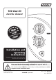
T80 Easi-Fit electric shower Installation and operating instructions Installers please note these instructions are to be left with the user Please read this book thoroughly and familiarise yourself with all instructions before commencing installation and keep it for future reference. The shower installation MUST be carried out by a suitably qualified person, in the sequence of this instruction book. EC Registered Design No.
INTRODUCTION - PLEASE READ PLEASE READ THIS IMPORTANT SAFETY INFORMATION Products manufactured by Triton are safe and without risk provided they are installed, used and maintained in good working order in accordance with our instructions and recommendations. WARNING: DO NOT operate shower if frozen, or suspected of being frozen. It must thaw out before using. DO NOT operate the unit if the showerhead or spray hose becomes damaged.
DO NOT operate the shower if water ceases to flow during use or if water has entered inside the unit because of an incorrectly fitted cover. WARNING: If restarting the shower immediately after stopping, be aware that a slug of IMPORTANT GENERAL GUIDANCE NOTES hot water will be expelled for the -first few seconds. 1 GENERAL 1.1 Isolate the electrical and water supplies before 2.3 DO NOT solder pipes or fittings within 300mm of the shower unit, as heat can transfer along the pipework and damage components.
GENERAL ADVICE TO USERS IMPORTANT ADVICE TO USERS The following points will help you understand how the shower operates: a. The electric heating elements operate at a constant rate at your chosen power setting. It is the rate of the water passing through the heater can which determines the water temperature. (The slower the flow, the hotter the water becomes; the faster the flow, the cooler the water). COMISSIONING ADVICE When first installed the unit will be empty.
CONTENTS Page INTRODUCTION IMPORTANT SAFETY INFORMATION (please read) Installation check list (please follow & complete) GENERAL GUIDANCE NOTES GENERAL ADVICE TO USERS - CLEANING ADVICE SPECIFICATIONS.............................................................................. 2 DIMENSIONS & CABLE/WATER ENTRY POINTS............................... 3 ELECTRICAL REQUIREMENTS........................................................ 4 - 5 INSTALLING THE SHOWER..................................................
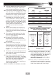
SECTION 1 check list SPECIFICATIONS ELECTRICAL Nominal power - rating at 240V Nominal power - rating at 230V 8.5kW – (40A MCB rating) 7.8kW – (40A MCB rating) 9.5kW – (40A MCB rating) 8.7kW – (40A MCB rating) PLUMBING (see page 6 & 7 for water regulations) Supply Source Mains pressure cold water only Minimum running pressure and flow to the inlet of the shower for full performance 100kPa (1.0 bar) at 8 litres per minute for 8.5kW & 9.
SECTION check list DIMENSIONS & ENTRY POINTS Fig.1 DIMENSIONS 225mm 101mm 333mm Fig.2 ENTRY POINTS WATER = Back = Others Left: Bottom, Back, Top & Side. Right: Bottom, Back, Top & Side. CABLE = Back = Others Left: Bottom, Back & Top. Right: Bottom, Back & Top. PLEASE NOTE: Deviation from the approved entry points will invalidate product specifications and warranty.
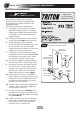
SECTION 3 check list ELECTRICAL REQUIREMENTS ELECTRICAL REQUIREMENTS WARNING Shepperton Park, Triton Road, Nuneaton, Warwickshire, CV11 4NR THIS APPLIANCE MUST BE EARTHED The installation, supply cable and circuit protection must conform with BS 7671 (IEE wiring regulations) and be sufficient for the amperage required. The following notes are for guidance only: 1 The shower must only be connected to a 230-240V ac supply.
fuse (see Table A). when the switch is in the OFF position, and the wiring must be connected to the switch SECTION without the use of a plug or socket outlet. 5.1 A 30mA residual current device (RCD) must be installed in all UK electric and pumped shower circuits. This may be part of the consumer unit or a separate unit. 6 3 Continued 6.
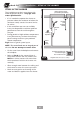
SECTION 4 check list Installation - SITING OF THE SHOWER SITING OF THE SHOWER Mains electric supply (via double pole switch) The installation must be in accordance with Water Regulations/Bylaws - see page 2 for water specifications • If it is intended to operate the shower at pressures above the maximum or below the minimum stated, contact Customer Service for advice.
SECTION Continued IMPORTANT: Water regulations (fig.6) 4 WARNING • It is required that the showerhead be ‘constrained by a fixed or sliding attachment so that it can only discharge water at a point not less than 25mm above the spill-over level of the relevant bath, shower tray or other fixed appliance’. The shower MUST NOT be positioned where it will be subjected to freezing conditions.
SECTION 5 check list Installation - PLUMBING INSTALLATION PLUMBING INSTALLATION IMPORTANT INFORMATION Plumbing to be carried out before wiring The outlet of the shower acts as a vent and must not be connected to anything other than the hose and showerhead supplied. • DO NOT use jointing compounds on any pipe fittings for the installation. • DO NOT solder fittings near the shower unit as heat can transfer along the pipework and damage components.
SECTION Installation - ELECTRICAL INSTALLATION 6 check list ELECTRICAL INSTALLATION NOTE: Deviations from the designated entry points will invalidate product approvals. The cable entry points are listed on page 3. IMPORTANT: Switch off the electricity supply at the mains before proceeding. • The supply cable MUST be secured either by routing through conduit, in trunking, or by embedding in the wall, in accordance with IEE regulations.
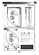
SECTION 7 Continued Fig.9 Top pipe trims Top cable “Cut out” entry points The backplate has removable top trims (top left and top right) that may be used for pipe entry and two additional sections (top left and top right) that may ONLY be used as a ‘cut out’ for top electrical cable entry (fig.9). The showers bottom trimplate has also been designed with four ‘cut out’ bottom/side water pipe access points and two ‘cut out’ electrical cable access points (fig.9).
SECTION Continued • Hook the backplate over the top screw and fit the bottom fixing screws into position, but DO NOT fully tighten the screws at this stage. The fixing holes are elongated to allow for out of square adjustment after the plumbing connection has been completed. 7 Fig.10 • Connect the mains water supply to the inlet DO NOT use excessive force when making the connection. • Make sure the backplate is square on the wall and tighten the retaining screws which hold it to the wall.
SECTION 7 Continued Fig.11 DO NOT DISCONNECT THE TOP WIRES Terminal block in left hand entry position 2 Terminal block in right hand entry position 3 1 Earth terminal 1 Terminal block - left or right entry The Terminal block is factory assembled as a ‘left’ electrical entry, but this can be altered to a ‘right’ electrical entry (fig.11). IMPORTANT: DO NOT disconnect the top wires.
SECTION 7 Continued • (fig.12) shows a schematic wiring diagram. IMPORTANT: When connecting the cable fully tighten the terminal block screws and make sure that no cable insulation is trapped under the screws. Loose connections can result in cable overheating. L E 2 1 5 N 3 3 6 NOTE: The supply cable earth conductor must be sleeved. The outer sheath of the supply cable must be stripped back to the minimum.
SECTION 8 Continued FITTING THE COVER - continued Figures 13, 14, 15 and 16 show the correct control knob position when replacing the cover. A.With the cover off the shower - turn the POWER selector spindle clockwise until the flat section is on the left hand side (fig.13). B. With the cover off the shower - turn the stabiliser valve spindle fully clockwise until resistance is felt (fig.14). Flat section to left hand side Fig.13 Stabiliser valve C.
SECTION !! IMPORTANT !! check list COMMISSIONING WARNING 9 Fig.17 Power selector to COLD Before normal operation of the shower, it is essential the following commissioning procedure is completed correctly. COMMISSIONING PROCEDURE The first operation of the shower is intended to flush out any remaining unit debris, and to make sure the heater unit contains water before the elements are switched on.
SECTION 10 check list Fig.19 USER OPERATING INSTRUCTIONS OPERATING THE SHOWER - Power selector (fig.19) Make sure the commissioning procedure has been carried out. To start the shower • Press the Start/Stop button and water will flow. High Cold To stop the shower • Press the Start/Stop button and water will cease to flow. Economy • After stopping the unit MUST be isolated via the 45amp isolating switch.
SECTION Continued To adjust the shower temperature Economy and High settings only • The water temperature is altered by increasing or decreasing the flow rate of the water through the shower via the temperature control (fig.19). • After obtaining your showering temperature, the knob can be left as the normal setting and should only need altering to compensate for seasonal changes in ambient water temperature.
SECTION 10 Continued OPERATING FUNCTIONS Fig.20 Power on indicator (fig.20) When the electricity supply to the shower is switched on at the isolating switch, the neon in the START/STOP button will illuminate. TP – Temperature Protection Low pressure indicator During normal operation if the temperature exceeds the showering safety limit the power to the elements will be removed completely, although water will continue to flow.
CLEANING THE FILTER INSTRUCTIONS FOR INSTALLERS ANDservice SERVICE engineers ENGINEERS ONLY Instructions installers only Instructions for installers andfor service engineers onlyand CLEANING THE FILTER It is recommended that the filter is periodically cleaned in order to maintain the performance of the shower. It is essential that this operation is carried out by a competent person. IMPORTANT: Before servicing, switch off the electricity supply at the mains.
FAULT FINDING/TROUBLESHOOTING IMPORTANT: Switch OFF the electricity at the mains supply and remove the circuit fuse before attempting any fault finding inside the unit. Problem/Symptom Cause Action/Cure 1 Shower inoperable, no water flow. 1.1 Interrupted power supply. 1.1.1 Blown fuse or circuit breaker. Check supply. Renew or reset fuse or circuit breaker. If it fails again, consult a qualified electrician. 1.2 Unit malfunction. 1.2 2.1 Not enough water flowing through the shower. 2.1.
FAULT FINDING/TROUBLESHOOTING Problem/Symptom 4 Water too cool or cold. (continued) Cause Action/Cure 4.4 Electrical malfunction. 4.4.1 Have unit checked by suitably qualified electrician or contact Triton Customer Service. 4.5 Safety cut-out operated. 4.5.1 Thermal safety cut-out device has operated. Have the unit checked by a suitably qualified engineer or contact Customer Service. 5 Shower varies from normal temperature to cold during use. 5.1 Water pressure has dropped below minimum required.
SPARE PARTS 13 1 14 7 10 9 2 4 5 7 3 8 11 3 12 2 9 8 1 6 15 10 4 16 11 5 12 6 13 14 15 Images are for reference only - due to continual development, supplied spares may have modified appearance 22
SPARE PARTS SPARE PARTS Ref. Description Part No. 1. Inlet Filter Assembly....................P82800843 2. Start/stop switch.........................P81901342 3. Can & Element Assembly............83314800 83314810 4. Switch carriage...........................P22611001 5. Pressure Switch...........................P22611003 6. Trimplate....................................7054303 7. Terminal block & loom...............S82201190 8. Outlet pipe & PRD......................S85000260 9.
24
25
WEEE Directive – Policy Statement As a producer and a supplier of electric showers, Triton Showers is committed to the protection of the environment via our own environmental policy and the compliance with the WEEE directive.
SHOWER CONTROLS - QUICK USER GUIDE To START or STOP your shower. The power light will illuminate. 1 2 3 To start the shower, press the Start/Stop button. To STOP the shower - press the Start/Stop button, then turn the isolator switch OFF. Turn the main power isolator switch ON 4 To alter the FLOW and Temperature of your shower - HEAT SETTINGS ONLY.
UK SERVICE POLICY TRITON STANDARD GUARANTEE In the event of a product fault or complaint occurring, the following procedure should be followed: 1. Telephone Customer Service on 0844 980 0750 having available, your details including post code, the model number and power rating of the product, together with the date of purchase and, where applicable, details of the particular fault. 2. If required, the Customer Service Advisor will arrange for a qualified engineer to call. 3.