
Operating instructions

4
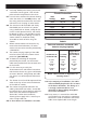
Meter
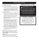
Incoming
supply
fuse
Meter
tails
Consumer
unit
Pull cord
isolating switch
Shower
unit
Fuse or
MCB
RCD
(can be part of
consumer unit)
80A or 100A
main switch
Schematic of installation circuit
ELECTRICAL REQUIREMENTS
Shepperton Park,
Triton Road, Nuneaton,
Warwickshire, CV11 4NR
E-002-A
The installation, supply cable and circuit
protection must conform with BS 7671 (IEE
wiring regulations) and be sufficient for the
amperage required.
The following notes are for guidance only:
1 The shower must only be connected to a
230-240V ac supply. If you are installing a
shower with a kilowatt rating above 9kW, it
is advisable to contact the local electricity
supply company.
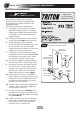
1.1 The electrical rating of the shower is shown
on the rating label (Fig.3) within the unit.
2 Before making any sort of electrical
connection within the installation make sure
that no terminal is live. If in any doubt,
switch off the whole installation at the mains
supply and remove the correct fuse.
3 The shower must be connected to its own
independent electrical circuit. IT MUST NOT
be connected to a ring main, spur, socket
outlet, lighting circuit or cooker circuit.
3.1 The electrical supply must be adequate for
the loading of the unit and existing circuits.
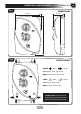
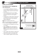
4 Check your consumer unit (main fuse box)
has a main switch rating of 80A or above
and that it has a spare fuse way which will
take the fuse or Miniature Circuit Breaker
(MCB) necessary for the shower (Fig.4).
4.1 If your consumer unit has a rating below
80A or if there is no spare fuse way, then the
installation will not be straightforward and
may require a new consumer unit serving
the house or just the shower.
4.2 You will need to contact the local electricity
company. They will check the supply and
carry out what is necessary.
5 For close circuit protection DO NOT use a
rewireable fuse. Instead use a suitably rated
Miniature Circuit Breaker (MCB) or cartridge
fuse (see Table A).
5.1 A 30mA residual current device (RCD) must
be installed in all UK electric and pumped
shower circuits. This may be part of the
consumer unit or a separate unit.
6 A 45 amp double pole isolating switch with
a minimum contact gap of 3 mm in both
poles must be incorporated in the circuit.
6.1 It must have a mechanical indicator showing
when the switch is in the OFF position, and
the wiring must be connected to the switch
without the use of a plug or socket outlet.
6.2 The switch must be accessible and clearly
identifiable, but out of reach of a person
using a fixed bath or shower, except for the
cord of a cord operated switch, and should
be placed so that it is not possible to touch
the switch body while standing in a bath or
shower cubicle. It should be readily
accessible to switch off after using the
shower.
7 Where shower cubicles are located in any
rooms other than bathrooms, all socket
outlets in those rooms must be protected by
a 30mA RCD.
8 The current carrying capacity of the cable
must be at least that of the shower circuit
protection (see Table B).
8.1 To obtain full advantage of the power
provided by the shower, use the shortest
cable route possible from the consumer unit
to the shower.
8.2 It is also necessary to satisfy the
disconnection time and thermal constraints
which means that for any given combination
of current demand, voltage drop and cable
size, there is a maximum permissible circuit
length.
9 The shower circuit should be separated from
other circuits by at least twice the diameter
of the cable or conduit.
9.1 The current rating will be reduced if the
cabling is bunched with others, surrounded
by thermal loft or wall insulation or placed in
areas where the ambient temperature is
above 30°C. Under these conditions,
derating factors apply and it is necessary to
select a larger cable size.
9.2 In the majority of installations, the cable
will unavoidably be placed in one or more
of the above conditions. This being so, it
is strongly recommended to use a
minimum of 10mm cabling throughout
the shower installation.
9.3 In any event, it is essential that individual
site conditions are assessed by a competent
electrician in order to determine the correct
cable size and permissible circuit length.
Fig.3
Fig.4
ELECTRICAL REQUIREMENTS
WARNING
THIS APPLIANCE MUST BE EARTHED
3
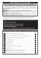
check list
SECTION