Disconnect Switches Product Guide Rotary Switches Non-fused Fused Enclosed Rotary Operating Mechanisms Accessories
Disconnect Switches 1 Manual Motor Disconnect Switches December 2004 Contents Description Rotary Disconnect Switches C362/C363 Product Description. . . . . . . . . . . . . . . . . . . . . . . . . . . . . . . . . . . . . . . . . . . . Features, Benefits and Functions . . . . . . . . . . . . . . . . . . . . . . . . . . . . . . . . . Standards and Certifications . . . . . . . . . . . . . . . . . . . . . . . . . . . . . . . . . . . . Options and Accessories . . . . . . . . . . . . . . . . . . . . . . . . .
Rotary Disconnect Switches Product Description 2 December 2004 ■ Product Description Features, Benefits and Functions Non-fused ■ ■ ■ R & W frame, 30A – 80A, non-fusible 600V AC , suitable for use in equipment or machinery as a motor disconnect. ■ Manual motor controller suitable for motor disconnect, horsepower and Amp rated, load break rated, meeting requirements of CSA C22.2 No 14 CEC rule 28-602 (3) (b) and UL508 “suitable for motor disconnect.
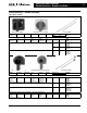
December 2004 Rotary Disconnect Switches Product Description Padlocking Handles can be padlocked in the OFF position with up to three padlocks. 1x 2x 3x 3 1 For safety reasons, the door cannot be opened when the handle is padlocked. maxi. ø 5 in / 8 mm 16 2 Door Interlock in ON Position Figure 1. Padlocking Capability (Type G Pistol Handle is Shown) The handles allow opening of the door in the OFF position only. In the ON position, the door cannot be opened.
Rotary Disconnect Switches Product Selection 4 December 2004 Product Selection — Switches Catalogue Ordering Information When ordering specify: Catalogue number of switch. Catalogue number of operating handle. Pages 5,6. Catalogue number of required shaft. Pages 5,6. Catalogue number of (optional) accessories. Page 7. ■ For dimensional data. Pages 8-15. ■ For technical data. Pages 16, 17. ■ ■ ■ ■ Table 1. Non-Fusible Switches Ampere Rating Maximum 3-Phase Horsepower Rating 240V 480V Table 2.
Rotary Disconnect Switches Product Selection – Handles and Shafts December 2004 Fusible/Non-Fusible Accessories Product Selection — Handles and Shafts Table 5. Handles and Shafts Red/Yellow Selector Handle Black Selector Handle NEMA Rating Defeatable Padlockable Color Operation IEC Type Selector Shafts Inches Dimensions mm Catalogue Number — — — CSBR5 CSYR6 CSBR6 2.2 4.3 5.9 55 110 150 CSSA055 CSSA110 CSSA150 7.1 7.9 11.8 180 200 305 CSSA180 CSSA200 CSSA300 4.7 7.9 11.8 15.
Rotary Disconnect Switches Product Selection – Handles and Shafts 6 December 2004 Table 5.
Rotary Disconnect Switches Fusible/Non-Fusible – Accessories December 2004 7 Product Selection — Accessories Table 3. Accessories — R, W-Frames Table 4.
Rotary Disconnect Switches– Non-fused Technical Data and Specifications M, R, W Frame 8 December 2004 Dimensions, Weights and Ratings Dimensions, weights and ratings given in this Product Guide are approximate and should not be used for construction purposes. Drawings containing exact dimensions are available upon request. All listed product specifications and ratings are subject to change without notice. Photographs are representative of production units.
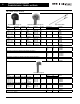
Rotary Disconnect Switches – Non-fused Technical Data and Specifications C-Frame December 2004 9 Dimensions in Inches (mm) C362UC30 C Dual Dimensions Inches (mm) A Y J J1 Y K1 X B K C363UC30CT C A Y J J1 Y K1 X B K H1 C363UC30JT C A Y J J1 Y K1 X B K Figure 5. C-Frames Table 7. Dimensions in Inches (mm) Description A B C H H1 H2 H3 J J1 K K1 Y 3.78 (96.0) 4.56 (115.8) 2.59 (65.8) — — — — 1.47 (37.3) .59 (15.0) 3.13 (79.5) 1.00 (25.4) 1.12 (28.
10 Rotary Disconnect Switches – Non-fused Technical Data and Specifications V-Frame December 2004 Dimensions in Inches (mm) C362UV60 C362UV100 C J 1.14 (29.0) .4 (10.2) Dual Dimensions Inches (mm) J1 Y K1 5 (127.0) X K Y C362UV200 B A 1.14 (29.0) C J1 J M 10 .4 (10.2) H2 Y K1 K 5 (127.0) X B 6.53 (165.9) H3 H2 J Y A Figure 6. Non-Fusible V-Frames Table 8. Dimensions in Inches (mm) Description A B C H H1 H2 H3 J J1 K K1 Y 6.69 (169.9) 5.87 (149.1) 3.
Rotary Disconnect Switches – Fusible Technical Data and Specifications V-Frame December 2004 11 Dimensions in Inches (mm) C363UV30CT / C363UV30C C363UV30JT / C363UV30J C363UV60JT / C363UV60J 1.14 (29.0) C .4 (10.2) Dual Dimensions Inches (mm) J1 J Y K1 5 (127.0) B X K A Y C C363UV100JT / C363UV100J C363UV200JT / C363UV200J J 1.14 (29.0) J1 .4 (10.2) M8 M10 H2 Y 5 (127.0) K1 X K3 K H3 H H2 Y J 10.24 (260.1) A Figure 7. Fusible V-Frames Table 9.
12 Rotary Disconnect Switches – Fusible Technical Data and Specifications V-Frame December 2004 Dimensions in Inches (mm) C363UV400JT / C363UV400J Dual Dimensions Inches (mm) C J 1.14 (29.0) M 10 J1 .4 (10.2) Y H2 K1 B 5 (127.0) K X 6.53 (165.9) H H3 H2 Y J H1 A Figure 8. Fusible V-Frames (Continued) Table 10. Dimensions in Inches (mm) Description 3-Pole A B C H H1 H2 H3 J J1 K K1 Y 11.93 (303.0) 14.31 (363.5) 5.56 (141.2) 5.28 (134.1) 11.41 (289.8) 7.04 (178.
Rotary Disconnect Switches – Non-Fusible Technical Data and Specifications S-Frame December 2004 13 Dimensions in Inches (mm) C362US400 C362US600 Dual Dimensions Inches (mm) J C Y J1 ø .51 ø (13.0) Y H K1 X H2 B K H 3.15 (80.0) H1 3.42 (86.9) A ø 1.3 ø (33.0) 2.36 (59.9) C362US800 C362US1000 C362US1200 K2 J 2.36 (59.9) C J1 Y Y H K1 X K2 B K 8.28 (210.3) 8.48 (215.4) 8.85 (224.8) H 4.72 (119.9) H1 A Figure 9. Non-Fusible S-Frames Table 11.
Rotary Disconnect Switches – Fusible Technical Data and Specifications F-Frame 14 December 2004 Dimensions in Inches (mm) 3.42 (86.9) C363UF600J C363UF800L Dual Dimensions Inches (mm) ø 1.30 ø (33.0) 2.36 (59.9) 2.36 (59.9) C H3 J 4.17 (105.9) J1 5.98 (151.9) Y H2 K1 B 9.17 (232.9) 9.52 (241.8) K X 12.67 (321.8) 9.53 (242.1) H 4.72 (119.9) Y A H1 Figure 10. Fusible F-Frames Table 12.
Rotary Disconnect Switches Technical Data and Specifications – Handles December 2004 15 Handles — Dimensions in Inches (mm) 2.44 (62) 0.49 (12.4) ø 1/16" (1.6) DOOR DRILLING 2.58 (65.5) 5/8" (16) 2.44 (62) 1.83 (46.5) 2ø 1/8" (3.2) ø 1-1/4" 0 - OFF 2" (50) (31) 0.69 (17.5) 2.48 (63) 0.31 (8) 1.5 (38) Figure 11. Selector Handle I - ON Figure 14. Pistol Handle — Type D DOOR DRILLING 2.87 (73) 90º ø 7/8" (23) 2.75 (70) 2" (50) 4ø 1/8" (3.2) 3.
Rotary Disconnect Switches Technical Characteristics 16 December 2004 Table 14. CSA Technical Characteristics Description R-Frame W-Frame Catalogue Number Catalogue Number C362NR30MD /C362TR30MD C362NR40MD /C362TR40MD C362NW60MD /C362TW60MD C362NW80MD /C362TW80MD 30A 40A 60A 80A CSA C22.2#14/CEC Rule 28-602/ (3)(b) CSA CSA CSA CSA Short Circuit Rating kA with Fuses 10 10 10 10 Fuse Class J J J J Rating Ampere Fuse Rating (A) 60 60 100 100 Maximum CSA 120V AC 2 3 5 7.
Rotary Disconnect Switches Technical Characteristics December 2004 17 Table 16.
Rotary Disconnect Switches – Enclosed Switches 18 December 2004 Enclosed Rotary ■ ■ ■ ■ ■ ■ ■ 30, 40, 60, 80 Ampere available. 600V, 3 pole, horsepower rated Type 12/3R, 4X Stainless and 4X Non Metallic Enclosures CSA approved to C22.2 #14 CEC rule 28-602(3) (b) manual motor controller suitable for motor disconnect Accepts auxiliary contacts Capability to signal PLC controller 10 kVA short circuit rating when used in conjunction with Class J fusing Table 17.
Rotary Disconnect Switches – Enclosed Switches December 2004 19 – Variable Depth CDR303UD CDR304UD 1.84 [47 MM] 5.19 [132 MM] 0 OFF 1.84 [47 MM] 6.86 [174 MM] 7.12 [181 MM] I ON .31 [8 MM] .312 DIA. [8 MM] T TYPE 12/3R ENCLOSURE. SCREW TO BE REMOVED WHEN USED AS TYPE 3R DEVICE 6.00 [152 MM] 7.84 [199 MM] 6.04 [153 MM] 4.66 [118 MM] 6.10 [155 MM] NOTE: 1. WIRE RANGE OF SWITCH LUGS IS #4-#14 COPPER. WIRE RANGE OF GROUND LUGS IS #2-#14 COPPER OR ALUMINUM.
Rotary Disconnect Switches – Enclosed Switches December 2004 CDR306UD CDR380UD 7.69 [195 MM] 4.99 [127 MM] 14.11 [[358 MM]] 14.37 [365 MM] 13.25 [[336 MM]] 4.99 [127 MM] 5.00 [127 MM] 15.09 [383 MM] 20 4.82 [[122 MM]] .312 DIA. [8 MM] 6.26 [[159 MM]] 8.54 [217 MM] TYPE 12/3R ENCLOSURE. SCREW TO BE REMOVED WHEN USED AS A TYPE 3R DEVICE. NOTE: 1. WIRE RANGE OF SWITCH LUGS IS #4-#14 COPPER. WIRE RANGE OF GROUND LUGS IS #2-#14 COPPER OR ALUMINUM. For more information visit us at: www.
Rotary Disconnect Switches – Enclosed Switches December 2004 21 CDR3030UW CDR3040UW Type 4X Stainless Enclosure 1.84 [47 MM] 1.84 [47 MM] 6.86 [174 MM] 7.12 [181 MM] 5.19 [[132 MM]] .312 DIA. [8 MM] 7.84 [199 MM] 6.00 [152 MM] 6.04 [153 MM] 4.54 [[115 MM]] 7.26 [[184 MM]] NOTE: 1. WIRE RANGE OF SWITCH LUGS IS #4-#14 COPPER. WIRE RANGE OF GROUND LUGS IS #2-#14 COPPER OR ALUMINUM. For more information visit us at: www.eatonelectrical.
Rotary Disconnect Switches – Enclosed Switches December 2004 – Flange Mounted – Fixed Depth CDR3080UW CDR3060UW Type 4X Stainless Enclosure 4.99 [127 MM] ON OFF 0 4.99 [127 MM] 14.37 [365 MM] 13.25 [336 MM] 4.70 [119 MM] 14.11 [358 MM] 7.69 [195 MM] 5.00 [127 MM] 15.09 [383 MM] 22 .31 [8 MM] .312 DIA. [8 MM] 7.42 [188 MM] 8.54 [217 MM] NOTE: 1. WIRE RANGE OF SWITCH LUGS IS #1-#14 COPPER. WIRE RANGE OF GROUND LUGS IS #2-#14 COPPER OR ALUMINUM. For more information visit us at: www.
Rotary Disconnect Switches – Enclosed Switches December 2004 23 CDR3040UX CDR3030UX Type 4X Non-Metallic Enclosure 312 [8 MM] DIA. 4 MOUNTING HOLES 7.47 [190 MM] 1.87 [47 MM] ON 1.87 [47 MM] OFF 6.75 [171 MM] 7.38 [187 MM] . 2.00 [51 MM] 4.72 [120 MM] 3.00 [76 MM] 7.43 [189 MM] 5.44 [138 MM] 5.50 [140 MM] NOTE: 1. WIRE RANGE OF SWITCH LUGS IS #4-#14 COPPER. WIRE RANGE OF GROUND LUGS IS #2-#14 COPPER OR ALUMINUM. CDR3060UX CDR3080UX Type 4X Non-Metallic Enclosure 15.88 [403 MM] 5.
Operating Mechanisms with Disconnect Switches – Variable Depth 24 Complete Operating Mechanism — C361NE1 Handle Only — C361H1 December 2004 Product Description Options and Accessories Type C361 Disconnect Switches are suitable for installation in control enclosures having a right-hand flange. Fusible disconnect switches will accept R fuses as standard. Field installable rejection kits are supplied as standard on 100A and 200A clips. For 30A and 60A rejection clips, see footnote .
Operating Mechanisms with Disconnect Switches – Variable Depth December 2004 Technical Data and Specifications Datum A D E F Datum C G .62 (15.7) 1.62 (41.1) Min. B Figure 15. Mounting Dimension Requirements Table 18. Mounting Dimension Requirements in Inches (mm) Disconnect Switch Type 30A and 60A Non-fusible 30A and 60A Fusible A B C D E F See Dimensions Below See Dimensions Below 1.56 (39.6) 1.56 (39.6) 1.75 (44.5) .96 (24.4) .96 (24.4) 1.10 (27.9) 4.00 (101.6) 4.00 (101.6) 5.
Operating Mechanisms with Disconnect Switches – Flange Mounted – Fixed Depth 26 Product Description December 2004 Table 23. Electrical Interlocks Type C361 Disconnect Switches are suitable for installation in control enclosures having a right-hand flange. Fusible disconnect switches will accept R fuses as standard. Field installable rejection kits are supplied as standard on 100A and 200A clips.
Operating Mechanisms with Disconnect Switches Accessories December 2004 Fuse Clips for Variable or Flange Mount Operating Mechanisms C351 Fuse Clip Kit Table 27.
28 Circuit Breaker Operating Mechanisms Flange Mounted – Fixed Depth December 2004 Product Description Type C371 Circuit Breaker Operating Mechanisms are designed for installation in control enclosures where main or branch circuit protective devices are required. All circuit breaker mechanisms are suitable for right hand mounting. Auxiliary contacts are not available for mounting on operating mechanism. Where required, have them installed in circuit breaker.
Circuit Breaker Operating Mechanisms Flange – Variable Depth, Flange Mounted – Fixed Depth December 2004 Mounting Dimension Requirements Dimension A = 0.75 in. plus the required wire bending spacing selected from Article 430-10 of the National Electrical Code. Dimension B = Minimum or maximum depth from inside of flange holding operating handle to panel where Circuit Breaker is mounted. (variable depth, see page 22) Dimension C = 150 Ampere Size – 0.67 in. 250 Ampere Size – 0.625 in. 400 Ampere Size – 0.
30 Notes NOTES December 2004 For more information visit us at: www.eatonelectrical.
December 2004 Notes For more information visit us at: www.eatonelectrical.
32 Notes December 2004 For more information visit us at: www.eatonelectrical.
Eaton Corporation is a diversified industrial manufacturer with 2003 sales of $8.1 billion. Eaton is a global leader in fluid power systems and services for industrial, mobile and aircraft equipment; electrical systems and components for power quality,distribution and control; automotive engine air management systems, powertrain solutions and specialty controls for performance, fuel economy and safety; and intelligent truck drivetrain syst for safety and fuel economy.